


Introduction
Heat resistance is not a side parameter for electromagnetic wire – it directly determines how long the equipment can run, what maximum temperature it can handle, and how much thermal shock it can absorb. In transformers, insulation system aging accounts for over 40% of all failure modes; in motors, the figure approaches 35%. The first threshold for electromagnetic wire selection is thermal class.
Paper covered wire‘s heat resistance is especially special. Unlike enameled wire where a single insulating varnish decides everything, paper covered wire’s heat performance depends on three combined factors: the insulating paper, the impregnating resin, and the conductor surface condition. This combination makes heat resistance evaluation more complex than enameled wire – one must consider paper thermal class, resin compatibility, and the synergistic aging of the oil-paper-resin system.
This article intends to make paper covered wire heat resistance completely clear – from thermal class classification, thermal aging mechanisms, material systems, Arrhenius life prediction, to heat performance testing methods, typical engineering application scenarios, and selection decision frameworks. We will use core standards such as IEC 60085, IEC 60172, IEEE Std 1, ASTM D2307, and UL 1446, while also incorporating nearly 30 years of practical experience in electromagnetic wire manufacturing and application.
Thermal Class Basic Theory and IEC 60085 Classification
The core of thermal class is the maximum allowable operating temperature – exceeding this temperature accelerates insulation aging, and service life will drop sharply from design life (typically 20-30 years) to just a few years or even months.
IEC 60085 is the internationally accepted standard for insulation thermal classification. It divides insulation materials into multiple classes by maximum allowable operating temperature: Y, A, E, B, F, H, N, R, 250, etc., with each class corresponding to a temperature range. NEMA (USA) and UL (North America) also have their own classification systems, but global mapping has been achieved through IEC 60085.
Engineering Significance of Thermal Class
Thermal class is not an arbitrary number – it is derived from extrapolation based on the Arrhenius thermal life model. Specifically, materials are aged at 9 temperature points for over 20,000 hours, then the maximum temperature corresponding to 20,000-hour life is back-calculated.
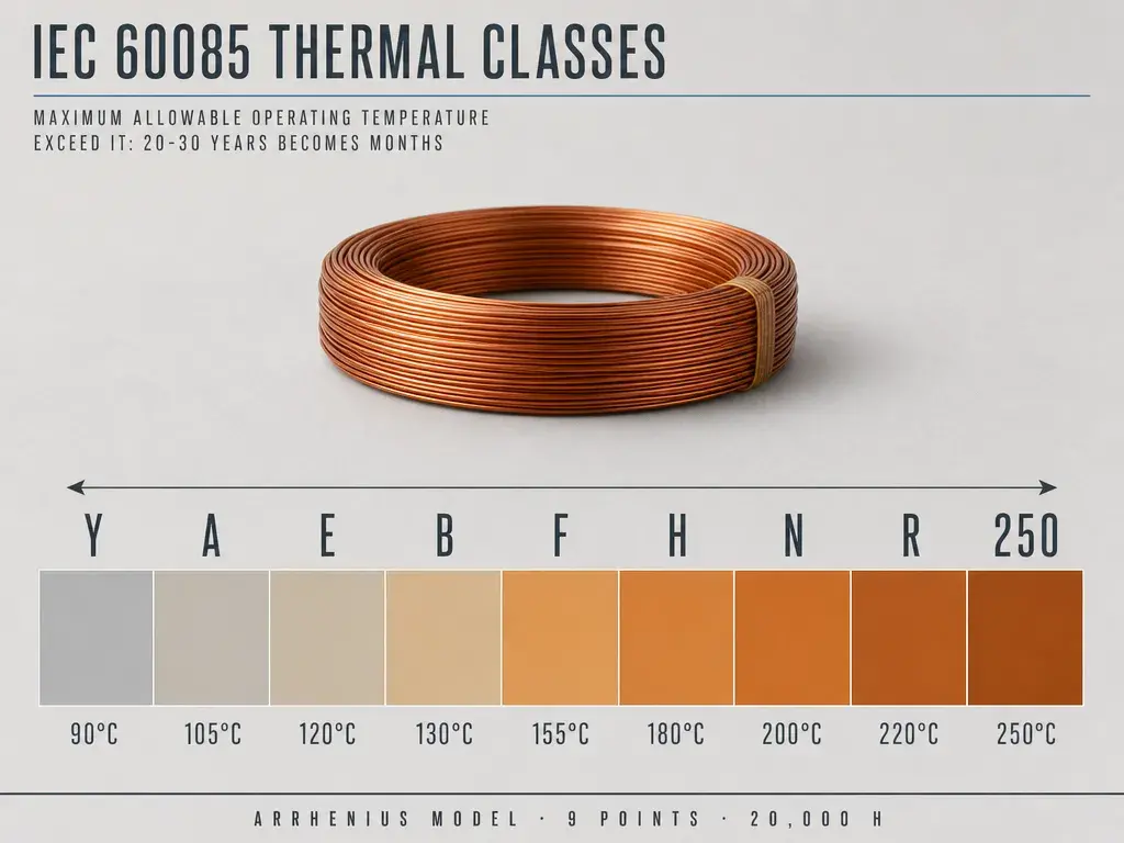
Complete IEC 60085 Thermal Class Classification
| Thermal Class (IEC 60085) | Old IEC Class | NEMA/UL Class | Maximum Hot Spot Temperature (°C) | Relative Thermal Endurance Index Range (°C) | Typical Materials |
|---|---|---|---|---|---|
| Y | Y | Y | 90 | >90 – 105 | Unimpregnated paper, silk, cotton, rubber, thermoplastics |
| A | A | A | 105 | >105 – 120 | Organic materials (cotton, silk, paper, synthetic fibers) |
| E | E | E | 120 | >120 – 130 | Polyurethane, epoxy resin, PET |
| B | B | B | 130 | >130 – 155 | Inorganic materials (mica, glass fiber, asbestos) |
| F | F | F | 155 | >155 – 180 | Class B + high-temperature binders |
| H | H | H | 180 | >180 – 200 | Silicone elastomers + Class B + high-temperature binders |
| N | N | N | 200 | >200 – 220 | Class F + PTFE |
| R | R | R | 220 | >220 – 250 | Class 200 + high-temperature materials |
| 250 | – | – | 250 | >250 | Polyimide enamel or polyimide film |
Iron rule: Every 10°C increase halves service life (Arrhenius rule of thumb). From Class A 105°C to Class H 180°C, the temperature difference is 75°C, theoretically shortening life to 1/2^7.5 ≈ 1/181.
Correspondence Between Thermal Class and Maximum Operating Temperature
In actual design, maximum operating temperature = hot spot temperature + ambient temperature + temperature rise + 10°C hot spot allowance. For example, Class A insulation, ambient 40°C, temperature rise 60°C, hot spot allowance 10°C, total 110°C – already exceeding the Class A 105°C limit. This is why oil-immersed transformers must control hot spot temperature below 95°C when using Class A 105°C.
Linkage Between Thermal Class, Insulation Thickness, and Breakdown Voltage
For every 10°C temperature increase, the breakdown voltage of most organic insulation materials decreases by approximately 5-8%. This means Class H 180°C insulation design breakdown voltage should provide 60-80% more safety margin than Class A 105°C – but actual design does not require this because Class H materials themselves have higher intrinsic breakdown field strength.
Thermal Aging Mechanisms
Insulation material aging at high temperature is not caused by a single factor, but by the combined action of four major mechanisms: thermo-oxidative degradation, thermal cracking, hydrolysis, and thermo-mechanical fatigue. Each mechanism has different time scales and manifestations.
Thermo-Oxidative Degradation
Oxygen + high temperature → cellulose molecular chain breakage → insulation paper strength decline, breakdown voltage reduction. This is the main aging mechanism for Kraft Paper at Class A 105°C. Antioxidants (amines, phenols) can delay this process, but Class A paper covered wire basically does not use them.
Thermal Cracking (Pyrolysis)
High temperature → molecular bond breakage → insulation embrittlement, carbonization. Nomex®, polyimide materials above Class H 180°C mainly face this aging. The higher the temperature, the faster the cracking rate – for every 30-50°C temperature increase, the cracking rate doubles.
Hydrolytic Degradation
Water + high temperature → ester bonds, amide bonds hydrolysis → molecular weight decline → mechanical strength loss. In oil-immersed transformers, moisture content is the key to hydrolysis – moisture content rising from 0.5% to 2% may halve the life of Class A paper.
Thermo-Mechanical Fatigue
Temperature cycling → thermal stress → CTE difference between insulation layer and conductor → interface delamination, paper layer separation. This is particularly common in traction motors and mining transformers with frequent start-stop. Copper CTE is 17×10⁻⁶/°C, insulation paper approximately 30-40×10⁻⁶/°C, a significant difference.
Synergistic Effects of Four Aging Mechanisms
Under actual operating conditions, the four aging mechanisms are superimposed rather than independent. In Class A oil-immersed systems, thermo-oxidation + hydrolysis are the main contradiction; in Class H dry-type systems, thermal cracking + thermo-mechanical fatigue are the main contradiction. Design selection must identify the dominant aging mechanism for specific scenarios.
Paper Covered Wire Thermal Class Material Systems
Paper covered wire’s thermal class is jointly determined by insulating paper type and impregnating resin type. The same Kapton/polyimide film with different impregnating resins can elevate thermal class from 200°C to 240°C.
Comparison of 6 Paper Covered Wire Insulating Material Thermal Classes
| Insulating Material | Chemical Composition | Thermal Class (IEC 60085) | Maximum Operating Temperature (°C) | Main Standards | Typical Applications |
|---|---|---|---|---|---|
| Kraft Paper | Cellulose | Class A | 105 | IEC 60317-27 / MW 31C, 33C | Oil-immersed transformer main insulation |
| Crepe Paper | Cellulose (stretched and wrinkled) | Class A | 105 | Enterprise standard | Transformer lead insulation |
| Thermally Upgraded Paper | Modified cellulose | Class E | 120 | Enterprise standard | Oil-immersed transformer upgraded insulation |
| Mica Tape | Mica + binder | Class F | 155 | Enterprise standard | High-voltage motor, traction motor |
| Nomex® Paper (meta-aramid) | Meta-aramid | Class H / N | 180 / 200 | IEC 60317-52, 53 / MW 60C, 61C | Dry-type transformer, automotive motor |
| Kapton® / Polyimide Film | Polyimide | Class R / 250 | 220 / 240 | IEC 60317-43, 44 / MW 62C, 63C | Automotive drive motor, aerospace |
Kraft Paper Upgrade Path (Class A → Class E)
Kraft Paper itself only has 105°C heat resistance, but through chemical modification (adding amines, cyano resins, etc.) it can be upgraded to Class E 120°C. This thermally upgraded paper is increasingly used in oil-immersed transformers, increasing transformer capacity by 10-15% and extending life by 30-50%.
Key Performance Comparison of High Temperature Insulation Materials
| Performance Indicator | Nomex® 410 | Mica Tape | Kapton® Film | Test Standard |
|---|---|---|---|---|
| Long-term Operating Temperature (°C) | 220 | 240+ | 240 | UL 746B / IEC 60216 |
| Short-term Temperature Resistance (°C) | 300 | 500+ | 400 | – |
| Dielectric Strength (kV/mm) | 18-30 | 20-25 | 200+ | ASTM D149 |
| Dielectric Constant ε_r | 2.5-3.0 | 5-7 | 3.5 | ASTM D150 |
| Tensile Strength (MPa) | 50-90 | 80-150 | 150-230 | ASTM D828 |
| Chemical Resistance | Excellent | Excellent | Outstanding | – |
| Cost (Relative) | High | Medium | Very High | – |
Influence of Impregnating Resin on Heat Performance
Impregnating resin not only determines the mechanical integrity of the insulation system, but also directly affects thermal class, thermal life, and thermal conductivity. In oil-immersed systems, the impregnating medium is transformer oil; in dry-type systems, the impregnating resin is epoxy, polyester, or silicone.
Mineral Oil Heat Performance in Oil-Immersed Systems
Mineral oil (transformer oil) heat performance indicators: flash point 135-160°C, fire point 165-185°C, kinematic viscosity ≤12 mm²/s @ 40°C, breakdown voltage ≥30 kV/2.5 mm, tan δ ≤0.005 @ 90°C. The oxidation stability of oil determines the thermal life of oil-immersed systems – the life of Class A 105°C oil-immersed systems is mainly determined by oil oxidation.
Thermal Class of Impregnating Resins in Dry-Type Systems
| Impregnating Resin | Thermal Class | Maximum Operating Temperature (°C) | Main Applications | Pros and Cons |
|---|---|---|---|---|
| Alkyd Resin | Class B | 130 | Early dry-type transformers | Low cost, poor heat resistance |
| Epoxy Resin | Class F | 155 | Dry-type transformer, motor | Strong bonding, chemical resistance |
| Polyester Resin | Class F | 155 | General motor, household appliance | Good flexibility |
| Silicone Resin | Class H | 180 | H-class dry-type transformer | High temperature resistance, high cost |
| Polyesterimide Resin | Class H | 180 | High-end motor, traction | Excellent overall performance |
| Polyamide-imide Resin | Class N / R | 200 / 220 | Automotive drive motor | Top heat resistance |
Thermal Effects of Resin-Paper Compatibility
Poor compatibility between resin and insulating paper causes interface gaps and delamination, affecting thermal conductivity. Nomex® 410 has excellent compatibility with epoxy resin; Kraft Paper has medium compatibility with alkyd resin; Mica has the best compatibility with silicone resin. Compatibility testing includes thermal cycling tests (-40°C to 180°C, 1,000 cycles, then check for delamination).
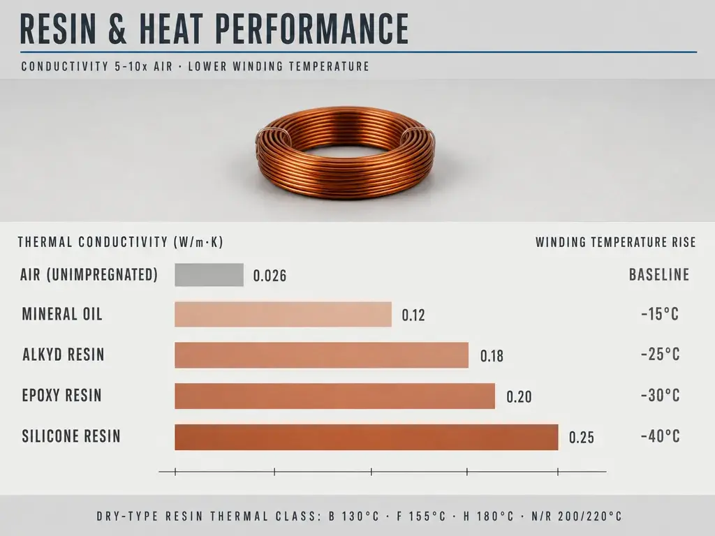
Influence of Resin Thermal Conductivity on Winding Heat Dissipation
| Impregnating Resin | Thermal Conductivity (W/m·K) | Winding Temperature Rise Contribution |
|---|---|---|
| Air (unimpregnated) | 0.026 | Baseline |
| Mineral Oil | 0.12 | -15°C |
| Alkyd Resin | 0.18 | -25°C |
| Epoxy Resin | 0.20 | -30°C |
| Silicone Resin | 0.25 | -40°C |
The thermal conductivity of impregnating resin is 5-10 times higher than air, making it a key path for winding heat dissipation.
Arrhenius Thermal Life Prediction Model
The Arrhenius model is the standard method for thermal life prediction. Its core idea is that insulation aging is a first-order chemical reaction, and the reaction rate has an exponential relationship with temperature.
Arrhenius Formula and Physical Meaning
“` k = A × exp(-Ea/RT) log₁₀ L = a + b/T
L = life (h) T = absolute temperature (K) a, b = material constants (fitted through 9 temperature points accelerated aging) Ea = activation energy (J/mol) R = gas constant (8.314 J/mol·K) “`
Physical meaning – as temperature rises, the extent of aging (chemical reaction rate) increases, and life decreases exponentially.
9-Point Temperature Extrapolation Standard Method
IEC 60172 and IEEE Std 1 specify the standard extrapolation method:
- Select 9 temperature points (typically 30-60°C above the thermal class)
- Age at each temperature point until failure (e.g., breakdown voltage drops 50%)
- Record the failure time (life) at each temperature point
- Perform linear regression on log₁₀ L vs 1/T plot
- Extrapolate to the target temperature (e.g., 105°C) to obtain 20,000 h life
Typical life-temperature data (Class A oil-immersed Kraft Paper):
| Aging Temperature (°C) | Failure Time (h) | log₁₀ L | 1/T (×10⁻³ K⁻¹) |
|---|---|---|---|
| 170 | 250 | 2.40 | 2.257 |
| 160 | 600 | 2.78 | 2.295 |
| 150 | 1,500 | 3.18 | 2.333 |
| 140 | 4,000 | 3.60 | 2.373 |
| 130 | 10,000 | 4.00 | 2.414 |
| 120 | 25,000 | 4.40 | 2.457 |
| 115 | 42,000 | 4.62 | 2.480 |
| 110 | 70,000 | 4.85 | 2.503 |
| 105 | 120,000 | 5.08 | 2.527 |
Regression equation: log₁₀ L = 12.5 – 4100/T → 105°C extrapolates 20,000 h life.
Rule of Thumb: 10°C Halving Rule
The engineering rule of thumb given by the Arrhenius model is: every 10°C increase halves life. This rule applies to organic insulation materials in the 100-200°C range.
Example: Class A 105°C design life 30 years → 115°C operating temperature → life shortened to 15 years → 125°C → 7.5 years → 135°C → 3.7 years.
Two-Segment Arrhenius Model
For multilayer or composite insulation (such as PEI + PAI double coating), the aging mechanism may change in the mid-temperature range (120-150°C), shifting from thermo-oxidation dominance to thermal cracking dominance. At this point, the single-segment Arrhenius model no longer applies, and a two-segment Arrhenius model is needed (set a transition point at 120-150°C).
Heat Performance Testing Methods
Paper covered wire’s heat performance testing is more complex than electrical testing – it requires long-time, multi-temperature-point accelerated aging, and uses statistical methods to back-calculate life.
Thermal Shock Testing (IEC 60851-6 Test 9)
Purpose: Detect insulation cracking and delamination ability under rapid temperature changes.
Method: Specimen held at high temperature (e.g., 150°C) for 30 min → quickly immersed in low temperature (e.g., -40°C) water or alcohol → check if insulation cracks or delaminates.
Judgment criteria: Class A 105°C / B 130°C / F 155°C / H 180°C / N 200°C / R 220°C have different temperature ranges respectively.
Softening Breakdown Testing (IEC 60851-6 Test 10)
Purpose: Detect insulation mechanical integrity at high temperature.
Method: Specimen heated to specified temperature → apply specified pressure (e.g., 5 N) → check for breakdown or penetration.
Softening breakdown temperature requirements: Class 130 ≥170°C / 155 ≥180°C / 180 ≥200°C / 200 ≥220°C / 220 ≥300°C.
Arrhenius Extrapolation Testing (IEC 60172 / IEEE Std 1)
Purpose: Predict long-term life of insulation system at specified temperature.
Method: 9 temperature points accelerated aging + periodic testing (e.g., breakdown voltage, tan δ) + failure judgment (e.g., 50% breakdown voltage decline) + linear regression extrapolation.
Typical duration: Single point aging 1,000-10,000 h, complete testing 1-3 years.
Thermogravimetric Analysis (TGA) and Differential Scanning Calorimetry (DSC)
TGA: Detects mass loss of materials at different temperatures, evaluates thermal stability. Kraft Paper starts decomposing at 200°C, completely decomposes at 350°C; Nomex® only significantly decomposes at 400°C.
DSC: Detects thermal transitions (glass transition, melting, decomposition) of materials. Can be used to evaluate thermal history and thermal aging extent.
Breakdown Voltage Thermal Stability Testing
Method: Measure breakdown voltage at 5 temperature points (room temperature, 60, 90, 120, 150°C) → fit breakdown voltage-temperature curve → evaluate temperature impact on breakdown.
Typical results: Kraft Paper breakdown drops 5-8% for every 10°C rise; Nomex® 410 breakdown drops 3-5% for every 10°C rise.
Comparison of 5 Heat Performance Testing Methods
| Testing Method | Testing Target | Temperature Range | Duration | Main Standard |
|---|---|---|---|---|
| Thermal Shock Test | Temperature cycling tolerance | -40~180°C | Several hours | IEC 60851-6 Test 9 |
| Softening Breakdown Test | High temperature softening point | 170-300°C | Several hours | IEC 60851-6 Test 10 |
| Arrhenius Extrapolation | Long-term life | 9 temperature points | 1-3 years | IEC 60172 / IEEE Std 1 |
| TGA/DSC | Thermal decomposition temperature | Room temp ~800°C | Several hours | ASTM E1131 / D3418 |
| Breakdown Voltage Thermal Stability | Temperature-breakdown curve | Room temp ~150°C | Several days | ASTM D149 |
Influence of Temperature Class on Insulation Geometry and Structure
The higher the temperature class, the more complex the insulation design – not only are materials upgraded, but the structure must also be redesigned.
Higher Temperature Class Demand for Insulation Thickness
Class A 105°C oil-immersed Kraft Paper single layer thickness is typically 0.05-0.25 mm; Class F 155°C mica tape single layer 0.10-0.50 mm; Class H 180°C Nomex® single layer 0.05-0.76 mm. Total insulation thickness increases with temperature class – but the thickening is for higher dielectric strength, not for higher heat resistance.
Thermal Advantages of Multilayer Composite Insulation
Single-layer insulation is prone to pinholes and hot spots at high temperature. Multilayer composite (such as Kraft + mica + glass fiber) can:
- Disperse thermal stress (different layers have different CTE)
- Provide redundant protection (one layer failure does not affect the whole)
- Improve thermal conductivity (interlayer interfaces increase heat dissipation paths)
Typical application: Class H dry-type transformers use Nomex® + epoxy resin multilayer composite.
Conductor Corner Radius Requirements for High Temperature Insulation
When temperature rises, electric field concentration at conductor corners becomes more severe (dielectric strength decreases). Class A 105°C conductor corner radius r ≥ 0.5 mm; Class H 180°C conductor corner radius r ≥ 0.8 mm; Class N 200°C conductor corner radius r ≥ 1.0 mm. Larger corners simultaneously reduce PD and thermal stress concentration.
Engineering Application Heat Scenarios
Paper covered wire’s heat resistance requirements vary dramatically across different application scenarios. Oil-immersed transformers require Class A 105°C; dry-type transformers require Class F 155°C or Class H 180°C; traction motors require Class H 180°C or Class N 200°C.
Oil-Immersed Transformer (Class A 105°C)
Oil-immersed transformers still predominantly use Class A 105°C insulation systems – Kraft Paper + mineral oil. Reasons:
- Most mature technology, most abundant operating experience
- Lowest cost for oil-paper system
- Best compatibility between mineral oil and Kraft Paper
Hot spot temperature control: Class A oil-immersed system hot spot temperature ≤95°C (GB/T 1094.2). Oil temperature ≤105°C. Oil-paper moisture content <0.5% is key.
Upgrade path: Through thermally upgraded paper, can upgrade to Class E 120°C, increasing transformer capacity by 10-15%.
Dry-Type Transformer and H-Class Motor (Class F 155°C / H 180°C)
Dry-type transformers use Nomex® 410 + epoxy resin or silicone resin impregnation, Class F 155°C or Class H 180°C. Oil-free, environmentally friendly, installable indoors, is the development direction for urban distribution transformers.
H-class motor: Power tools, industrial robots, servo motors. Nomex® + polyesterimide or silicone resin impregnation. Good thermal shock performance, can withstand frequent start-stop.
High-Voltage Motor (Class F 155°C / H 180°C)
High-voltage motor stator windings use mica tape + glass fiber + VPI (Vacuum Pressure Impregnation) epoxy resin. Class F 155°C or Class H 180°C. VFD (Variable Frequency Drive) scenarios require Class H + corona-resistant design.
Traction Motor and Rail Transit (Class H 180°C / N 200°C)
Traction motors bear high vibration, frequent start-stop, and high temperature. Insulation uses mica paper + glass fiber + epoxy resin composite. Class H 180°C or Class N 200°C.
Thermal shock scenarios: Rail transit IEC 61373 specifies -40~180°C temperature shock, 1,000 cycles without cracking.
New Energy Vehicle Drive Motor (Class H 180°C / N 200°C)
800V platform NEV drive motor is the current extreme challenge for thermal design – Class H 180°C is the bottom line, Class N 200°C is the trend. Insulation uses Kapton/polyimide film + mica + epoxy. Oil cooling (ATF) or water cooling (ethylene glycol) is the mainstream cooling method.
Thermal life requirement: 15 years or 300,000 kilometers – this means Class H 180°C must maintain 15-year life at 180°C operating temperature.
Wind Power and Offshore Applications (Class H 180°C / N 200°C)
Offshore wind farm transformers and generators face salt spray, humidity, temperature cycling (-20~60°C environment). Insulation uses Class H 180°C or Class N 200°C Nomex® or Kapton systems. IEC 60068-2-60 mixed gas flow test is required certification.
High Temperature Extreme Environment Thermal Design
In certain special scenarios, paper covered wire needs to withstand extreme temperatures above 200°C. This places more stringent requirements on the insulation system.
Core Challenges of Insulation Systems Above 200°C
200°C is the boundary between Class N 200°C and Class R 220°C. Above 200°C, traditional cellulose insulation (Kraft, Crepe) has completely failed and must switch to aromatic polymers (Nomex, Kapton).
Core challenges:
- Heat resistance limits of impregnating resins (epoxy ≤180°C, silicone ≤220°C, polyimide ≤260°C)
- Accelerated conductor oxidation (copper oxidation rate doubles above 200°C)
- Thermal expansion difference (copper 17×10⁻⁶/°C, Kapton 20×10⁻⁶/°C, 18% difference)
Aerospace and Military (Class R 220°C / 250°C)
Aviation AS22796 / 165 wire insulation systems, military MIL-W-22759 wires all require Class R 220°C or Class 250°C. Polyimide film (Kapton) is the mainstream solution.
Special requirements: Low outgassing (vacuum environment), radiation resistance (space environment), flame retardant (FAR 25.853).
New Energy Vehicle 800V High Voltage Platform (Class N 200°C / R 220°C)
800V platform drive motor insulation systems face dual challenges:
- Electrical: PDIV ≥3× operating voltage (much higher than traditional 400V platform)
- Thermal: Oil temperature 120°C + hot spot 200°C coexisting
Mainstream solution: Kapton film + mica + epoxy / polyimide impregnation. ATF oil cooling is required heat dissipation.
High Temperature Extreme Environment Selection Decision Tree
“` Operating temperature ≤105°C → Class A oil-immersed Kraft Paper system Operating temperature 105-120°C → Class E thermally upgraded paper system Operating temperature 120-155°C → Class F mica tape + epoxy system Operating temperature 155-180°C → Class H Nomex + silicone / polyimide system Operating temperature 180-200°C → Class N Nomex / Kapton + polyimide system Operating temperature 200-220°C → Class R Kapton + polyimide system Operating temperature 220-250°C → Class 250 polyimide + special resin system Operating temperature ≥250°C → Ceramic insulation + mica + glass fiber system “`
Standards System Comparison
Paper covered wire thermal class testing standards cover multiple systems including IEC, NEMA, UL, IEEE, ASTM, GB, and JIS.
Core Thermal Performance Testing Standards Comparison
| Standard Number | Standard Name | Test Content | Applicable Scope |
|---|---|---|---|
| IEC 60085 | Electrical insulation thermal classification | Thermal class definition | Global |
| IEC 60172 | Enameled wire thermal endurance test | Arrhenius extrapolation | Enameled wire, winding wire |
| IEC 60076-2 | Power transformer temperature rise | Transformer thermal design | Oil-immersed transformer |
| IEC 60216 | Electrical insulating materials thermal endurance | Thermal life evaluation | General insulation materials |
| IEC 60851-6 | Winding wire thermal performance test | Thermal shock, softening breakdown | Winding wire |
| IEEE Std 1 | Motor insulation thermal evaluation | Thermal life | North American motor |
| IEEE Std 98 | Insulation material thermal aging | Aging test method | North American general |
| ASTM D2307 | Enameled wire thermal endurance | Thermal aging test | Enameled wire |
| ASTM D3850 | TGA test method | Thermogravimetric analysis | General materials |
| ASTM D3418 | DSC test method | Differential scanning calorimetry | General materials |
| UL 1446 | Insulation system certification | EIS system certification | North American insulation system |
| UL 746B | Polymer long-term performance | Thermal life index | North American polymer |
| GB/T 4074 | Winding wire test methods | China equivalent to IEC 60851 | Chinese market |
| GB/T 1094.2 | Power transformer temperature rise | China equivalent to IEC 60076-2 | Chinese transformer |
Differences Between Different Standards Systems
IEC system: Emphasizes thermal class classification and Arrhenius extrapolation. 60085 defines thermal class, 60172 specifies extrapolation method, 60851-6 specifies specific tests.
ASTM system: Emphasizes precise measurement of material thermal performance. TGA/DSC measure thermal decomposition temperature, thermal transition temperature.
IEEE system: Emphasizes engineering applications of motors and transformers. IEEE Std 1, IEEE Std 98 are the core of motor insulation thermal evaluation.
UL system: Emphasizes North American market system certification. UL 1446 is EIS (Electrical Insulation System) certification, UL 746B is polymer thermal life index.
GB/T system: Equivalent adoption of IEC standards, but adds tan δ, temperature rise and other limits suitable for China power grid characteristics.
Third-Party Certification Bodies
International: UL (USA), CSA (Canada), VDE (Germany), TÜV (Germany/Europe), SGS (Switzerland), Intertek (USA/UK).
China: China Electric Power Research Institute, Shanghai Cable Research Institute, CTI (China).
Certification process: UL 1446 EIS certification process takes 3-6 months, including material testing, system testing, thermal aging, and final review.
Selection Decision Framework
Paper covered wire heat resistance selection requires comprehensive consideration of 4 dimensions: operating temperature, application scenario, compliance requirements, and cost constraints.
4-Step Selection Decision Framework
| Step | Evaluation Dimension | Key Parameters | Decision Output |
|---|---|---|---|
| Step 1 | Operating Temperature | ≤105°C / 105-155°C / 155-180°C / 180-200°C / ≥200°C | Thermal class, insulating paper, resin |
| Step 2 | Application Scenario | Oil-immersed / Dry-type / High-voltage motor / Traction / NEV / Wind power | Insulation structure, composite solution |
| Step 3 | Compliance Requirements | IEC / ASTM / GB / NEMA / UL 1446 / Specific industry | Certification, testing standards |
| Step 4 | Cost Constraint | Economy / Balanced / High-performance | Material grade, process simplification |
Thermal Class Recommendations for Different Application Scenarios
| Application Scenario | Recommended Insulation Structure | Thermal Class | Operating Temperature (°C) | Key Testing |
|---|---|---|---|---|
| Oil-immersed Transformer | Kraft Paper + mineral oil | Class A | 105 | Arrhenius, tan δ, moisture content |
| Oil-immersed Transformer Upgraded | Thermally upgraded paper + mineral oil | Class E | 120 | Arrhenius, tan δ, moisture content |
| Dry-type Transformer | Nomex® 410 + epoxy | Class F | 155 | Thermal shock, softening breakdown, PD |
| Dry-type Transformer (High-end) | Nomex® 410 + silicone resin | Class H | 180 | Thermal shock, softening breakdown, PD |
| High-Voltage Motor (VFD) | Mica tape + glass fiber + VPI | Class F / H | 155 / 180 | PDIV, thermal shock, thermal life |
| Traction Motor (Rail Transit) | Mica + glass fiber + epoxy | Class H | 180 | IEC 61373 vibration, EN 45545-2 HL3 |
| NEV Drive Motor (400V) | Kapton + mica + epoxy | Class H | 180 | PDIV, thermal cycling, AEC-Q200 |
| NEV Drive Motor (800V) | Kapton + mica + polyimide | Class N | 200 | PDIV, oil cooling compatibility, AEC-Q200 |
| Wind Power (Onshore) | Nomex® + epoxy | Class H | 180 | IEC 60068-2-60, thermal cycling |
| Wind Power (Offshore) | Kapton + Nomex® + polyimide | Class N | 200 | IEC 60068-2-60, salt spray, humidity |
Common Selection Mistakes and Avoidance Methods
Mistake 1: Thermal class does not match actual operating temperature. Class A 105°C oil-immersed system working at 120°C (temperature rise exceeds limit), causing breakdown after only 6 years of aging resistance. Avoidance method: Measure actual operating temperature (environment + temperature rise + hot spot allowance), select corresponding thermal class or 1 level higher.
Mistake 2: Ignoring compatibility between impregnating resin and insulating paper. Kraft Paper has poor compatibility with silicone resin, causing interface delamination and breakdown voltage drop of 30%. Avoidance method: Reference compatibility data provided by suppliers, or conduct thermal cycling test verification (-40~180°C, 1,000 cycles).
Mistake 3: Single-point Arrhenius extrapolation applied to multilayer composite insulation. Kraft + mica + glass fiber composite system aging mechanism changes at 120-150°C, single-point Arrhenius gives incorrect prediction. Avoidance method: Use two-segment Arrhenius model or segmented verification.
Mistake 4: Ignoring thermo-mechanical fatigue. Class H 180°C traction motor after frequent start-stop (50 start-stops per day, 547,500 times total over 30 years), interface delamination causes breakdown. Avoidance method: Thermal cycling test (IEC 60068-2-14) + vibration test (IEC 61373).
Conclusion
Paper covered wire heat resistance is the first threshold for equipment reliability – selecting the wrong thermal class makes all subsequent insulation design a castle in the air.
Paper covered wire remains irreplaceable in oil-immersed transformers – the Class A 105°C oil-paper combination has been verified for nearly a century, with the most mature technology, richest operating experience, and optimal cost. Dry-type transformers, H-class motors, and NEV drive motors require Nomex® or Kapton solutions above Class H 180°C.
There are three core principles for heat resistance selection: first, thermal class must have 10-20°C margin, cannot be at the limit; second, impregnating resin and insulating paper must be compatible, perform thermal cycling verification when necessary; third, Arrhenius extrapolation must use 9 temperature points, cannot be simplified.
—
We Zhengzhou LP Industry Co.,Ltd. are a source manufacturer with 30 years of experience in the electromagnetic wire export industry, with our factory located in Zhengzhou, Henan, featuring a 60-acre modern production base equipped with ISO 9001/14001/45001 certification and SGS-audited production lines. Our paper covered wire product specifications cover round wire 0.016-7.0 mm and flat wire (thickness 0.8-10 mm, width 2-25 mm), with thermal endurance grades 155/180/200/220/240°C, compliant with IEC/GB/JIS/NEMA international standards, and exported to more than 50 countries. For technical support or sample requests, please contact: Email office@cnlpzz.com / WhatsApp 0086-19337889070.