


Voltage Concept and Basics of Dielectric Breakdown Breakdown voltage is a key electrical parameter of the enamel coating insulation in magnet wire. It defines the critical voltage at which the enamel coating abruptly changes from an insulating state to a conducting state under the influence of an electric field. Understanding this parameter is crucial for the safe operation of motors, transformers, and appliance windings. Simply put—when the voltage rises to a certain value, the enamel coating suddenly loses its insulating ability, and current flows directly through the insulation layer to the conductor. This is called “breakdown.” Once breakdown occurs, the insulation of the enamel coating at that location is permanently lost and cannot be restored.
Physical Essence of Dielectric Breakdown The enamel coating is a dielectric material. Under an applied electric field, the molecules in the enamel coating become polarized; the stronger the electric field, the stronger the polarization. When the electric field strength exceeds the dielectric strength (in V/μm or kV/mm) of the enamel coating, electrons inside the coating gain sufficient energy to undergo avalanche ionization, instantly forming a conductive channel. This process lasts for an extremely short time—on the order of nanoseconds (10⁻⁹ seconds). Once the conductive channel is formed, the enamel coating is permanently destroyed at the breakdown point, resulting in a short circuit between turns or to ground in the winding at that location.
Breakdown Voltage
Voltage vs. Dielectric Strength vs. Voltage Resistance These three concepts are often confused in engineering, but their physical meanings are completely different: – Dielectric Strength: An inherent property of the enamel coating material itself, measured in V/μm or kV/mm. Polyurethane enamel coatings have a dielectric strength of approximately 170 V/μm, polyester imide approximately 200 V/μm, and polyimide can reach 250 V/μm. – Breakdown Voltage: The measured voltage value of the entire enameled wire during testing, measured in volts (V) or kV. It is an engineering result of dielectric strength × enameled coating thickness. – Withstand Voltage: The voltage value that the magnet wire should withstand under normal operating conditions, typically the full range of the breakdown voltage (generally taken as 50-75%). In engineering, breakdown voltage is used to quantify the insulation capability of the magnet wire, dielectric strength to describe the enameled coating material, and voltage resistance to confirm batch quality.
Breakdown Voltage in Magnet Wire Applications
Significance of Breakdown Voltage in Magnet Wire Applications Breakdown voltage directly determines the reliability of the magnet wire in motor/transformer windings: – Motor Windings: Inter-turn voltage peaks can reach hundreds of volts to kilovolts (in variable frequency drive conditions). Insufficient breakdown voltage can lead to inter-turn short circuits and burn out the motor. – Transformer Windings: Interlayer voltage can reach several kilovolts (high-voltage transformers), and insufficient breakdown voltage can lead to interlayer breakdown and explosion. – High-frequency coils: The skin effect concentrates current near the enamel coating, and insufficient breakdown voltage can lead to corona discharge and ablation. – New energy drive motors: With the widespread adoption of 800V high-voltage platforms, breakdown voltage has become a critical safety indicator. A German OEM we recently contacted explicitly requires that the breakdown voltage of enameled wire for 800V platform drive motors be ≥ 6 kV (Ø1.0 mm Grade 2), which is significantly higher than the 4 kV requirement for traditional 400V platforms.
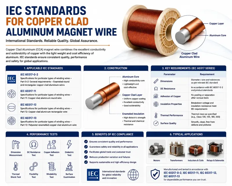
IEC 60851-5
Standard Breakdown Voltage Test Method IEC 60851-5 is an internationally recognized standard for testing the electrical performance of winding wires, specifically specifying the breakdown voltage test method (Test 13). Understanding this standard is crucial for procurement and quality control.
Basic Principles of Breakdown Voltage Test IEC 60851-5 Test 13 specifies the breakdown voltage test method as follows: 1. Specimen Preparation: The enameled wire is wound into a coil-wound specimen according to the specified method. 2. Electrode Connection: A gradually increasing AC voltage (50 Hz or 60 Hz) is applied across the specimen. 3. Voltage Increase Rate: Typically 100-500 V/s (rapid method) or 50 V/s (standard method). 4. Breakdown Detection: When the current suddenly increases beyond a set threshold (typically 5 mA), this voltage value is recorded as the breakdown voltage. 5. Number of Tests: The median of 5 specimens is taken as the representative value. The test results are normalized according to the enameled coating thickness to obtain the dielectric strength (V/μm or kV/mm), facilitating comparison between different wire diameters.
Electrode Forms: Twist Pair / Straight Wire / Shot Electrode IEC 60851-5 specifies three test electrode forms suitable for different wire diameters and applications: – Twist Pair: Two enameled wires are twisted together as two electrodes. This is the most common method for 0.05-2.5 mm round wires. – Straight Wire: The enameled wire passes through a metal electrode, which serves as the other electrode. Suitable for small wire diameters (<0.1 mm). – Shot Electrode: A mercury pellet or copper bead is used to contact the enameled wire. Suitable for large wire diameters and flat (rectangular) wires. NEMA MW 1000 has adopted the shot electrode method as the primary test method for large round and flat wires (based on IEC 60851-5).
Voltage Ramp Rate on Breakdown Voltage Results The voltage ramp rate directly affects the breakdown voltage test results: – Rapid Ramp (500 V/s): Breakdown voltage is higher (10-15%) because insulation defects do not have time to develop. – Standard Ramp (100 V/s): IEC standard method, most stable results. – Slow Ramp (20 V/s): Breakdown voltage is lower (5-10%), closer to the actual operating voltage. In engineering, the IEC standard method (100 V/s) is usually used, but some customers specify the rapid method for online QC sampling to save testing time.
Test 14 / Test 19: Other Related Electrical Tests IEC 60851-5 also includes 3 related electrical tests: – Test 5 (Electrical Resistance): Conductor DC resistance test, confirming copper/aluminum conductor purity and cross-sectional area. – Test 14 (Continuity of Insulation): Insulation continuity test (high-voltage spark test), 100% online testing. – Test 19 (Dielectric Dissipation Factor): Dielectric loss factor (tan δ) test, assessing losses under high-frequency operating conditions. These four tests together constitute a complete electrical performance evaluation system for enameled wire.
NEMA MW 1000
Standard and AWG Breakdown Voltage Specification NEMA MW 1000 is the comprehensive American standard for magnet wire, widely referenced by the IEC 60317 series of standards. The two standards are highly coordinated in terms of breakdown voltage specifications, but differ in the details of the test methods. ###
| NEMA MW 1000 | IEC 60317 | Enamel Coating Type | Thermal Class |
|---|---|---|---|
| MW 15-C | 60317-3 | Polyurethane (UEW) | 155°C / Class F |
| MW 30-C | 60317-8 | Polyester (PEW) | 155°C / Class F |
| MW 35-C | 60317-13 | Polyesterimide (EIW) | 180°C / Class H |
| MW 76-C | 60317-46 | Polyamide-imide (AIW) | 220°C / Class C |
| MW 81-C | 60317-56 | Polyimide (PIW) | 240°C / Class C |
NEMA MW 1000 vs IEC 60317
Harmonization Relationship The magnet wire types covered by NEMA MW 1000 correspond one-to-one with the IEC 60317 series: | NEMA MW 1000 | IEC 60317 | enamel coating type | thermal class | |————–|———–|———-|———-| | MW 15-C | 60317-3 | Polyurethane (UEW) | 155°C / Class F | | MW 30-C | 60317-8 | Polyester (PEW) | 155°C / Class F | | MW 35-C | 60317-13 | Polyesterimide (EIW) | 180°C / Class H | | MW 76-C | 60317-46 | Polyamide-imide (AIW) | 220°C / Class C | | MW 81-C | 60317-56 | Polyimide (PIW) | 240°C / Class C | The breakdown voltage specifications are highly consistent between the two standards, with differences typically ≤5%.
NEMA MW 1000
Breakdown Voltage Specification (AWG Grade) NEMA MW 1000 minimum breakdown voltage specified by AWG wire gauge grade (Grade 1/2/3): | AWG Size | Conductor Diameter (mm) | Grade 1 (V) | Grade 2 (V) | Grade 3 (V) | |———-|—————|————-|————-|————-| | 14 | 1.63 | 1500 | 2700 | 4000 | | 18 | 1.02 | 900 | 1700 | 2500 | | 24 | 0.51 | 500 | 900 | 1400 | | 30 | 0.25 | 250 | 500 | 800 | | 36 | 0.127 | 110 | 250 | 400 | | 40 | 0.079 | 75 | 150 | 250 | | 44 | 0.051 | 50 | 100 | 175 | Grade 1 = Thinnest enamel coating / Grade 2 = Standard / Grade 3 = Thickened enamel coating. Higher Grades result in higher breakdown voltage. ###
Applicable Specifications
Shot Electrode Method in Large Diameter/Flat Wire NEMA MW 1000 specifies the use of the shot electrode method for large diameter wires (>AWG 14) and flat wires (rectangular wires): – Test Principle: The enameled wire passes through a container filled with mercury pellets or copper beads, which act as another electrode. – Applicable Specifications: Round wire Ø1.63 mm and above, flat wire cross-sectional area ≥4 mm². – Test Voltage: Calculated at 1 kV/mm enamel coating thickness (AC peak). – Breakdown Criterion: A sudden current increase exceeding 5 mA. The advantages of the shot electrode method are stable contact and good test repeatability; the disadvantage is the toxicity of mercury (environmental risk). Modern factories tend to use copper beads or graphite pellets instead.
Voltage Gradients of the Three Major Enamelled Coating Materials The enamel coated material is the decisive factor in breakdown voltage. Polyurethane (PU/UEW), polyester imide (PEI/EIW), and polyimide (PI/PIW) are the three most commonly used enamel coated materials in engineering, and their breakdown voltage gradients differ significantly.
Voltage Characteristics of Polyurethane (UEW / QA) The breakdown voltage characteristics of polyurethane enamel coating (UEW, IEC 60317-3) are as follows: – Dielectric Strength: 150-180 V/μm (approx. 15-18 kV/mm) – Typical enamel coating thickness: Ø0.5 mm wire Grade 2 approx. 18-22 μm – Breakdown Voltage: Ø0.5 mm Grade 2 ≈ 2.7-4.0 kV – Advantages: Low-temperature soldering (380°C soldering iron required), good high-frequency performance – Disadvantages: Thermal class only 155°C (Class F), relatively low breakdown voltage. Polyurethane is mainly used in small transformers, relay coils, and applications requiring soldered terminals.
Imine (EIW / QZY) Breakdown Voltage Characteristics The breakdown voltage characteristics of polyester imine enamel coating (EIW, IEC 60317-13) are as follows: – Dielectric Strength: 200-230 V/μm (approx. 20-23 kV/mm) – Typical enamel coating thickness: Ø0.5 mm line Grade 2 approx. 20-25 μm – Breakdown Voltage: Ø0.5 mm Grade 2 ≈ 4.0-5.8 kV – Advantages: Temperature resistance up to 180°C (Class H), breakdown voltage 30-40% higher than PU – Disadvantages: Cannot be directly soldered (requires mechanical stripping) Polyester imine is currently the main enamel coating material for industrial motors and household appliance motors.
Voltage Characteristics of Polyimide (PIW / QY) The breakdown voltage characteristics of polyimide enamel coating (PIW, IEC 60317-56) are: – Dielectric Strength: 240-280 V/μm (approx. 24-28 kV/mm) – Typical enamel coating thickness: Ø0.5 mm wire Grade 2 approx. 22-28 μm – Breakdown Voltage: Ø0.5 mm Grade 2 ≈ 5.3-7.8 kV – Advantages: Temperature resistance up to 240°C (Class C), highest breakdown voltage, radiation resistance – Disadvantages: Highest cost (3-5 times that of PEI), difficult processing Polyimide is mainly used in extreme conditions such as military, nuclear power, aerospace, and traction motors.
Breakdown Voltage Enhancement of Dual-Coating
Voltage Enhancement of Dual-Coating Modern high-end magnet wires commonly use dual-coating enamel coating structures:
– Base Coating: Polyester imide (PEI), 15-20 μm thick, providing mechanical strength and heat resistance. – Top Coating: Polyamide-imide (AIW), 5-10 μm thick, providing breakdown voltage enhancement (an additional 30-50%). – Total Breakdown Voltage: Ø0.5 mm Grade 2 double coating can reach 6.5-8.0 kV. Double-coated structures are most widely used in new energy vehicle drive motors (800V platform) and variable frequency motors.
Wire Test Method Explained
Method Comparison: Twist Pair vs Straight Wire vs Shot Electrode. These three IEC 60851-5 standard test methods each have their own characteristics in terms of test conditions, applicable specifications, and result consistency.
Pair Test Method Explained Twist Pair (twisted pair) is the most classic breakdown voltage test method for 0.05-2.5 mm round wires: – Sample Preparation: Take two enameled wires and twist them at a tension of 125 N/cm² (12 twists per 10 cm) to form uniform contact. – Electrode Connection: Connect one wire to the high-voltage end and the other to ground. – Voltage Boosting Program: Increase the voltage from 0V to breakdown at 100 V/s. – Breakdown Criterion: Current > 5 mA. – Result Calculation: Take the median of 5 samples. The Twist Pair test result reflects the “withstand voltage” of the enamel coating, providing the most intuitive engineering significance.
Wire Test Method Explained Straight Wire testing is mainly used for small wire diameters (<0.1 mm): – Sample Preparation: Pass the enameled wire through a metal electrode (such as a copper tube), which is grounded. – Electrode Contact: A circuit is formed through the contact between the metal electrode and the enameled wire. – Applicable Specifications: Ø0.016-0.10 mm round wire (AWG 46-38). – Special Considerations: Small wire diameters have thin enamel coatings and low breakdown voltage (10-200 V), requiring a high-precision voltage source. Small wire diameters are mainly used in miniature inductors, sensor coils, hearing aid drivers, etc.
Electrode Test Method Details Shot Electrode testing is mainly used for large wire diameters and flat wires: – Sample Preparation: The enameled wire passes through a container filled with pellets (mercury pellets/copper beads/graphite pellets). – Electrode Contact: The pellets make multi-point contact with the enameled wire surface, forming a uniform electric field. – Applicable Specifications: Round wire Ø>1.63 mm, flat wire cross-sectional area ≥2 mm². – Test Voltage: Calculated based on 1 kV/mm enamel coating thickness. Large-diameter magnet wire is mainly used in large transformers, wind turbine windings, and rail traction motors.
Factors Affecting Breakdown Voltage
Test Results from Three Methods | Test Method | Applicable Wire Diameter | Test Voltage Range | Result Repeatability | Test Time | Engineering Applications | |———|———|————-|————|———|———-| | Twist Pair | 0.05-2.5 mm | 10V-10kV | ±5% | 30 s | Industrial Motors/Household Appliances | | Straight Wire | <0.1 mm | 1V-200V | ±8% | 20 s | Miniature Inductors/Sensors | | Shot Electrode | >1.63 mm | 1kV-30kV | ±3% | 60 s | transformer/traction motor |
Factors Affecting Breakdown Voltage Breakdown voltage is affected by four main factors: enamel coating thickness, temperature, humidity, and boost rate. Understanding these factors is crucial for adapting to operating conditions and quality control.
Influence of Enamell Coating Thickness on Breakdown Voltage Enamell coating thickness directly determines breakdown voltage: – Linear Relationship: Breakdown voltage ≈ Dielectric strength × Enamell coating thickness – Grade 1 (Thin Enamell Coating): Breakdown voltage is approximately 60-70% of Grade 2 – Grade 3 (Thick Enamell Coating): Breakdown voltage is approximately 150-170% of Grade 2 – Tolerance: Enamell coating thickness deviation within the same batch is ±15%, corresponding to a breakdown voltage deviation of ±15%. In engineering, Enamell coating thickness is specified according to AWG 14/18/24 wire diameter grades, indirectly determining the breakdown voltage.
Effect of Temperature on Breakdown Voltage As temperature increases, breakdown voltage decreases: – Room temperature (25°C): Breakdown voltage is 100% of the baseline value. – Class F temperature (155°C): Breakdown voltage drops to 75-85%. – Class H temperature (180°C): Breakdown voltage drops to 65-75%. – Class C temperature (220°C): Breakdown voltage drops to 50-60%. For every 10°C increase in temperature, the breakdown voltage decreases by approximately 5-8%. This is why motor windings are prone to inter-turn short circuits after prolonged operation at high temperatures.
Effect of Humidity on Breakdown Voltage Humidity (water vapor) is the biggest enemy of breakdown voltage: – Dry environment (<50% RH): Breakdown voltage has almost no effect. – Medium humidity (50-80% RH): Breakdown voltage decreases by 10-20%. – High humidity environment (>90% RH): Breakdown voltage decreases by 30-50%. – Condensation state (100% RH): Breakdown voltage decreases by 50-70%. Water vapor penetrates the micropores of the enamel coating, forming conductive channels. This is why enameled wire must be stored in a sealed container to avoid long-term exposure to humid environments.
Impact of Voltage Boost Rate on Breakdown Voltage The engineering significance of voltage boost rate affecting test results: – Rapid boost (500 V/s): Insulation defects do not have time to develop, resulting in a higher breakdown voltage. – Standard boost (100 V/s): IEC standard, stable results. – Slow boost (20 V/s): Defects develop fully, resulting in a lower breakdown voltage. In practical engineering, the choice of voltage boost rate depends on the test objective—rapid methods are used for QC spot checks, and standard methods are used for type testing.
Voltage vs. Dielectric Strength vs. Voltage Resistance
Voltage vs. Dielectric Strength vs. Voltage Resistance (Core Concept Differentiation) These three concepts are often used interchangeably in engineering literature, but their physical meanings are completely different. Accurate differentiation is crucial for standard selection and test report interpretation. ### Dielectric Strength Dielectric strength is an inherent property of the enamel coating material itself: – Unit: V/μm or kV/mm (standardized parameter) – Physical Meaning: The maximum electric field strength that a unit thickness of enamel coating can withstand. – Determining Factors: The molecular structure and chemical bond strength of the enamel coating material. – Typical Values: PU 150-180 V/μm / PEI 200-230 V/μm / PI 240-280 V/μm Dielectric strength is a material property, independent of the enamel coating thickness, and is a core parameter for comparing enamel coating materials. ### Breakdown Voltage Breakdown voltage is a measured parameter of the entire enameled wire: – Unit: V or kV (measured voltage value) – Physical Meaning: The peak voltage that the entire enameled wire and its enamel coating can withstand. – Determining Factors: Dielectric strength × enamel coating thickness – Typical Value: Ø0.5 mm PEW Grade 2 ≈ 4.0-5.8 kV Breakdown voltage is an engineering measurement value and is related to wire diameter, enamel coating thickness, and testing method.
Voltage Resistance (Withstand Voltage)
Voltage resistance (Withstand Voltage) Voltage resistance is a safety parameter under design operating conditions: – Unit: V or kV (design voltage value) – Physical meaning: The voltage that the enameled wire should be able to withstand over a long period of time under actual operating conditions – Determining factors: Breakdown voltage × Ampere rating (typically 0.5-0.75) – Typical value: Ø0.5 mm PEW Grade 2 voltage resistance ≈ 2.0-4.0 kV Voltage resistance is an engineering design parameter used for selection and operating condition adaptation.
Relationship
Diagram and Engineering Selection Dielectric strength (material property) × enamel coating thickness = Breakdown voltage (measured value) Breakdown voltage × Ampere full range rating (0.5-0.75) = voltage resistance (design value) When selecting for engineering, first select the enamel coating material (PU/PEI/PI) based on dielectric strength, then select the enamel coating thickness based on wire diameter and grade to calculate the breakdown voltage, and finally determine the full range rating based on operating voltage and life requirements to obtain the voltage resistance.
Mechanism and Partial Discharge (PD) Triggering Mechanism Breakdown voltage failure is not a single factor, but the result of the combined effects of five major stresses: heat, humidity, electricity, chemical, and mechanical. Among them, partial discharge (PD) is the key triggering mechanism under high-frequency operating conditions.
Explanation of Partial Discharge (PD) Triggering Mechanism Partial discharge (PD) is a micro-discharge that occurs in tiny voids or bubbles within the enamel coating: – Causes of Formation: Solvent evaporation and temperature gradients during the enamel coating process lead to bubbles/voids. – Discharge Process: Gas (air/nitrogen) in the void ionizes under high voltage, generating a micro-discharge (pC level). – Energy Release: Each PD releases 1-10 nC of charge, accompanied by localized high temperatures (on the order of 1000°C). – Cumulative Effect: Long-term PD causes gradual carbonization of the enamel coating, forming electrical trees, eventually leading to breakdown. PD is not significant at 50/60 Hz power frequency, but deteriorates rapidly under variable frequency drive (IGBT switching frequency 5-20 kHz).
Aging Failure Mechanism Thermal aging is a cumulative process of breakdown voltage decrease: – Temperature Threshold: Above 20°C, the aging rate increases by 2 times. – Molecular Changes: Polymer molecular chains break and crosslink, making the enamel coating brittle. – Breakdown Voltage Changes: After 1000 hours of aging, the breakdown voltage decreases by 20-40%. – Arrhenius Model: ln(lifetime) = A + B/T (T is absolute temperature), used for accelerated life prediction. Thermal aging is the main failure mode after long-term operation of motor windings.
Heat Coupling Failure Mechanism: Humidity and temperature work together to accelerate the decrease in breakdown voltage: – Moisture Absorption: PU enamel coating has the highest moisture absorption (2-3%), PEI has a medium absorption (1-2%), and PI has the lowest (<1%). – Hydrolysis Reaction: At high temperatures, water vapor reacts with the enamel coating, leading to molecular chain breakage. – Accelerated Aging: Under 85°C/85% RH conditions for 1000 hours, the PEI breakdown voltage decreases by 30-50%. – Engineering Countermeasures: Impregnation treatment of the enameled wire fills the micropores of the enamel coating, blocking moisture channels. Humidity and heat coupling is a major cause of motor failure in tropical, marine, and industrial steam environments.
Mechanical Stress and Breakdown Voltage Mechanical stress (bending, vibration, tension) damages the enamel coating, reducing the breakdown voltage: – Insufficient Bending Radius: Tensile cracking of the enamel coating reduces the breakdown voltage by 30-50%. – Repeated Bending: After winding 10 turns on a 1× diameter mandrel, the breakdown voltage decreases by 20-30%. – Vibration Fatigue: Long-term vibration causes microcracks in the enamel coating, lowering the PD initiation threshold. – Engineering Countermeasures: Control the bending radius to ≥ 3 times the enameled wire diameter and select a highly flexible enamel coating material. The winding process has a significant impact on the final breakdown voltage.
Applications and Quality Control
Applications and Quality Control (Motors/Transformers/Home Appliances/New Energy Vehicles) Breakdown voltage has different engineering requirements and quality control methods in four major application scenarios.
Voltage Requirements for Motor Windings Motor windings (especially for new energy vehicle drive motors) have the highest breakdown voltage requirements: – Conventional motors (400V platform): Breakdown voltage ≥ 4 kV (Ø1.0 mm Grade 2) – 800V high-voltage platform motors: Breakdown voltage ≥ 6 kV (Ø1.0 mm Grade 2) – Variable frequency drive motors: Voltage resistance ≥ 10 kV/μs (dv/dt withstand) – Typical enamel coating structure: PEI + AIW double coating (Ø1.0 mm, total breakdown voltage 6-8 kV) German Tier 1 OEMs require enameled wires to pass the IEC 60851-5 Test 13 breakdown voltage test, with a minimum value ≥ 6.5 kV for 5 samples.
Breakdown Voltage Requirements for Transformer Windings
Breakdown Voltage Requirements for Transformer Windings Breakdown voltages for transformer windings are specified in tiers according to voltage levels:
| Transformer Type | Voltage Rating | Breakdown Voltage Requirement | Recommended Enamel Coating |
|————|———-|————–|———-|
| Low Voltage Transformer | <1 kV | ≥3 kV (Ø0.5 mm G2) | PEW / EIW |
| Distribution Transformer | 1-35 kV | ≥5 kV (Ø1.0 mm G2) | EIW + AIW |
| Power Transformer | 35-220 kV | ≥8 kV (Ø2.0 mm G3) | Double Coating + Oil Immersion |
| High Voltage Test Transformer | >220 kV | ≥15 kV (Ø3.0 mm G3) | Paper Insulation + PI Enamel Coating |
Power transformers typically employ a multi-insulation structure of enameled wire + paper insulation + impregnated varnish.
Voltage Requirements for Home Appliance Windings Home appliance motors (air conditioners, refrigerators, washing machines) have relatively low breakdown voltage requirements: – Small appliance motors: Breakdown voltage ≥ 2.5 kV (Ø0.5 mm G2 PEW) – White goods compressor motors: Breakdown voltage ≥ 4 kV (Ø0.8 mm G2 PEW/PEI) – High-speed vacuum cleaner motors: Breakdown voltage ≥ 5 kV (Ø0.6 mm G2 PEI) – Typical enamel coating structure: PEW or PEI single coating (prioritizing cost-effectiveness) The key to home appliance motors is not high breakdown voltage, but stability and cost.
Voltage Requirements for New Energy Vehicle Motors New energy vehicle drive motors have the most stringent breakdown voltage requirements: – 400V platform drive motor: Breakdown voltage ≥ 5 kV (Ø1.0 mm G2 double coating) – 800V platform drive motor: Breakdown voltage ≥ 7 kV (Ø1.0 mm G2 double coating) – PTC heater winding: Breakdown voltage ≥ 3 kV (high temperature resistance 200°C+) – Charging station/transformer: Breakdown voltage ≥ 10 kV (Ø2.0 mm G3 PI double coating) In a recent European new energy vehicle 800V drive motor project, the customer explicitly required the enameled wire to pass both IEC 60851-5 Test 13 and NEMA MW 1000 certifications, with a minimum breakdown voltage ≥ 7.5 kV.
Control System and Acceptance Process Quality Control System for Breakdown Voltage of enameled wire: – Incoming Quality Control (IQC): Sampling according to AQL 1.0 for each batch, tested according to IEC 60851-5 Test 13. – Online Quality Control (IPQC): 100% pass the spark test (Test 14) online inspection. – Outline Quality Control (OQC): Quarterly testing according to NEMA MW 1000 full-item testing. – Certification Reports: Third-party reports from UL / IEC 60317 / NEMA MW 1000 / GB/T 6109. The factory must establish a complete IQC + IPQC + OQC system, with traceable breakdown voltage data.
Engineering Summary
From a material perspective, breakdown voltage gradients of magnet wire follow a clear hierarchy: polyurethane (UEW) provides 15-18 kV/mm dielectric strength, polyester imide (EIW) provides 20-23 kV/mm, and polyimide (PIW) reaches 24-28 kV/mm; dual-coating structures combining PEI + AIW can further increase this by 30-50%, achieving 6.5-8.0 kV for Ø1.0 mm Grade 2 wire.
From an application perspective, breakdown voltage requirements differ significantly across scenarios: new energy vehicle 800V platform drive motors require ≥6 kV for Ø1.0 mm Grade 2; traditional 400V motors require ≥4 kV; home appliance motors (air conditioners, washing machines, refrigerators) require 2.5-4 kV; and distribution transformers require ≥5 kV for Ø1.0 mm Grade 2. Test methods also vary by wire diameter—twist pair for 0.05-2.5 mm round wire, shot electrode for large diameter and flat wire.
From a quality control perspective, the IEC 60851-5 Test 13 standard method with 100 V/s ramp rate provides stable breakdown voltage values; voltage resistance (the engineering design parameter) equals breakdown voltage × 0.5-0.75 ampere derating; humidity above 90% RH can decrease breakdown voltage by 30-50%, and every 10°C temperature rise decreases it by 5-8%. PD (partial discharge) under high-frequency variable frequency drives is the key failure triggering mechanism, making enameled wire selection closely tied to operating frequency, voltage platform, and ambient conditions.