

Introduction: Efficiency Is Not Just a Nameplate Number
In the transformer industry, “efficiency” is a frequently used but rarely clearly defined term. When efficiency differences are repeatedly discussed, they essentially involve three different levels of questions: Why do different manufacturers produce different efficiency levels for the same transformer? How much will efficiency change after the winding conductors are replaced with different insulation systems? Is efficiency determined by the design stage or by accidental factors during operation?
Paper covered wire is essentially an insulating material, not an efficiency-enhancing material. Claiming that a single insulating material “improves efficiency” is inaccurate. Its true role in efficiency lies in the following: the addition of a paper sheath to the conductor allows for precise design of the winding geometry, effectively reducing dielectric losses, accurately controlling thermal resistance, and continuously suppressing partial discharge. These four factors collectively determine the overall shape of the transformer’s loss distribution.
This article first establishes the accounting basis for loss composition, then breaks down the action path of paper covered wire line by line, and then provides the selection and implementation path, typical application cases, failure modes and standard verification basis.
Loss Accounting: The Efficiency Baseline
Transformer Efficiency Equation and the Two Loss Sources
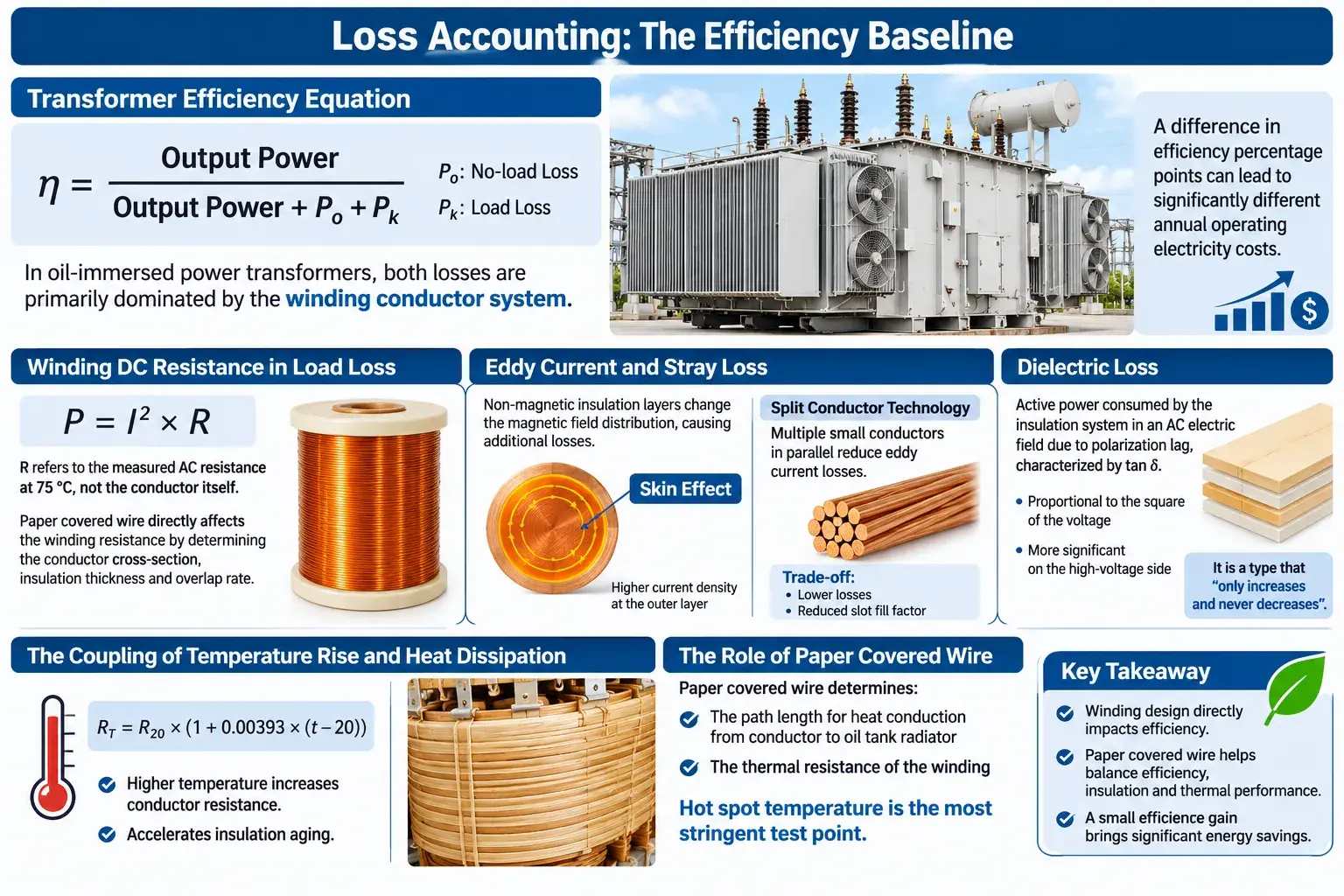
The transformer efficiency formula is η = Output Power / (Output Power + no load loss P₀ + load loss Pₖ). The numerator is a given value, while the two losses in the denominator are the variables.
The key judgment lies in the fact that, in medium- and high-voltage oil-immersed power transformers, both losses in the denominator are primarily dominated by the winding conductor system. The core portion is determined by the laminated silicon steel sheet structure and the tank’s heat dissipation capacity, while the winding portion depends almost entirely on the conductor geometry and insulation structure. A difference in efficiency percentage points corresponds to significantly different annual operating electricity costs on large equipment.
Winding DC Resistance in Load Loss
The main component of load loss is the active power consumed by the DC resistance of the winding, calculated as P = I² × R. Here, R refers to the measured AC resistance of the winding at a reference temperature of 75 °C, not the resistance of the conductor itself. A transformer winding consists of tens to hundreds of turns of wire connected in series; the resistance of a single turn is accumulated to form the total winding resistance.
This is the path most affected by paper covered wire. The windings need to accommodate the same number of turns within the same core window; the distribution of conductor cross sectional area, insulation thickness, and overlap rate directly determines the winding resistance.
Eddy Current and Stray Loss
In addition to the DC resistance of the windings, load losses also include eddy current losses and stray losses. The non-magnetic material introduced into the inter turn insulation layer alters the magnetic field distribution, creating additional losses.
This factor is often underestimated. eddy currents induced inside the conductor by winding leakage flux are directly related to the geometry of the inter turn insulation and the electric field concentration at the conductor corners. The mechanism of eddy current loss and the skin effect is the same: uneven current distribution across the conductor cross-section, with higher current density in the outer layer than in the inner layer, reduces the equivalent conductive area. The more turns in the winding, the larger the conductor cross-section, and the higher the frequency, the more pronounced this effect becomes. Split conductor technology addresses this by replacing a single large-section conductor with multiple small-section conductors wound in parallel, reducing the spatial scale of the eddy current loop to a size much smaller than the skin depth, thus decreasing losses.
The costs are clearly stated: gaps exist between the parallel conductors, reducing slot fill factor and decreasing the conductor cross-section that can be accommodated within the same window area. This is a trade-off between geometric efficiency and electrical efficiency, and these costs must be calculated during the design phase.
Dielectric Loss
Dielectric loss is the active power consumed by an insulation system in an alternating electric field due to polarization lag, and is usually characterized by the dielectric loss factor tan δ. It is proportional to the square of the voltage, and therefore its effect is significantly amplified on the high-voltage side. For medium and high-voltage transformers, although its absolute value is much smaller than the winding resistance loss, it belongs to the type that “only increases and never decreases”.
The Coupling of Temperature Rise and Heat Dissipation
An increase in winding temperature causes the conductor resistance to rise according to Rₜ = R₂₀ × (1 + 0.00393 × (t − 20)), while simultaneously accelerating the thermal aging of the insulation material. Efficiency and lifespan are coupled here and are not two independent metrics that can be discussed separately.
The significance of paper covered wire in thermal terms lies in its determination of the path length and thermal resistance of heat conduction from the conductor surface to the oil tank radiator. The hot spot temperature of the winding is the most stringent test point.
Winding Geometry and DC Resistance Loss
How Insulation Thickness Occupies the Effective Fill Factor
Slot fill factor is a core indicator of winding geometry. The ratio of the cross sectional area of the bare conductor to the actual occupied slot cross sectional area determines the number of turns that can be accommodated for a given core size.
Every slight increase in insulation thickness comes at a cost to the slot fill factor, which is directly converted into the winding’s DC resistance. The more conductor cross-sections packed into the same window area, the lower the resistance. This is the first constraint in paper covered wire design: insulation thickness and conductor cross sectional area are a pair of quantities that need to be optimized simultaneously, rather than being independent technical parameters.
Thickness Tolerance Management
The insulation thickness tolerance requirements for paper covered wire are much stricter than those for enameled wire. During the paper layer winding process, the thickness deviation of each layer will accumulate into the total thickness.
A common engineering practice is to control the tolerance along the negative tolerance direction to ensure that the thinnest point still meets the breakdown voltage requirement, rather than distributing it bidirectionally around the nominal value. The reason is that the electrical strength of the insulation system is determined by the thinnest point, not by the average value.
Setting the Overlap Ratio
There is a significant difference in the overlap rate between round wire wrapping and flat wire wrapping. A higher overlap rate results in a longer creepage distance and a greater breakdown margin, but a portion of the effective insulation layer thickness is occupied by the overlap area.
NEMA MW 1000-2018 requires that rectangular and square aluminum magnet wires wrapped in aromatic polyamide paper have at least two layers of paper and that the overlap ratio be no less than the specified lower limit. This figure is a lower limit constraint, not an optimal value, and the actual value needs to be determined in conjunction with the working voltage level and the dielectric properties of the oil.
Corner Geometry and Electric Field Concentration
Electric field concentration occurs at the corners of flat wire windings. If the corner radius is too small, local field strength peaks will form at the corners, and the corner region is precisely where the inter turn insulation is thinnest.
The directions for geometric optimization are: increasing the fillet radius, adopting a segmented conductor structure, and adjusting the conductor arrangement. The trade-offs are a decrease in the effective cross sectional area ratio and an increase in the complexity of the termination process.
Geometric Parameters and Their Efficiency Consequences
The table below lists geometric parameters alongside efficiency consequences, which can be used to determine the adjustment levers for each parameter.
| Geometric parameters | Adjust direction | Effect on winding DC resistance | Effects on eddy currents and stray losses | Main cost |
|---|---|---|---|---|
| conductor cross sectional area | Increase | direct drop | Basically unchanged | A decrease in slot fill factor necessitates either enlarging the core or lengthening the windings. |
| Insulation layer thickness | Decrease | decline | No direct impact | Breakdown margin and creepage distance decrease |
| Overlap rate | reduce | Basically unchanged | No direct impact | partial discharge margin decreases |
| conductor fillet radius | Increase | Basically unchanged | decline | The difficulty of termination and clamping processes has increased. |
| Number of conductor strands | Increase | decline | Significant decline | Slot fill rate decreases, termination becomes more complex. |
| inter turn distance | Increase | No direct impact | Affecting leakage reactance consistency | Slot fill rate decreased |
Dielectric Loss and Low-Loss Insulation System Design
Dielectric Properties of Cellulose Paper
Cellulose paper, as an insulating material, has a low dielectric constant, and its tan δ after drying and impregnation can be very low. This value constitutes the source of the advantage of paper covered wire in terms of dielectric loss. Equally important is its volume resistivity; the volume resistivity of the insulating paper after drying and impregnation is very high, meaning that the conductivity loss of the insulation system itself can be ignored.
Drying
Paper covered wire typically needs to be thoroughly dried in a vacuum oven before winding. The reason is clear: cellulose paper is highly hygroscopic, and increased moisture content directly raises tan δ and lowers the partial discharge initiation voltage.
If this process is not controlled, all subsequent efforts will be in vain. The purpose of vacuum drying is not simply to dry the paper, but to reduce the moisture content inside the paper to an acceptable level and maintain it.
Impregnation
After drying comes impregnation. Oil immersed transformers are impregnated with mineral oil, while dry type transformers are impregnated with VPI (vacuum pressure impregnation) resin.
Impregnation has a triple function: filling the air gaps between paper layers to eliminate the starting point of partial discharge caused by air gaps, increasing dielectric strength, and dissipating heat.
Selecting the Paper Base Material Grade
Thicker insulation paper is not always better. Common types include kraft paper, crepe paper, Nomex 410, Nomex 414, and mica paper.
- kraft paper—General purpose, low cost, moderate mechanical strength, suitable for lower voltage levels
- crepe paper—The crepe structure provides greater oil impregnation thickness and creepage distance.
- Nomex 410 – Aromatic polyamide paper with high heat resistance and excellent heat aging performance.
- Nomex 414—a modified Nomex 410 with further improved heat resistance and mechanical properties.
- mica paper—highest heat resistance rating, used in high-temperature or special applications.
The selection criteria are a combination of voltage level, temperature level and mechanical requirements, rather than a single-dimensional horizontal comparison.
| Insulating paper type | Typical thickness range | Heat resistance rating | Applicable occasions |
|---|---|---|---|
| kraft paper | medium | 105 °C level | Low voltage level distribution transformer |
| crepe paper | medium | 105 °C level | Applications requiring greater creepage distance |
| Nomex 410 | Wider range | 180 °C | High-temperature operating conditions, traction and special transformers |
| Nomex 414 | Wider range | 180 °C | High-voltage windings with higher mechanical strength requirements |
| mica paper | medium | 220 °C | Extremely high temperature or special heat resistance requirements |
The heat resistance rating in the table refers to the upper limit of the thermal rating of the insulating paper itself. The final usable temperature rating is determined by the weakest link among the paper, varnish, and impregnating medium. This is precisely why the section on insulation rating matching emphasizes that downgrading is not allowed.
Self-Healing Capability
One of the lesser-known advantages of cellulose paper is its self healing ability. When partial discharge creates tiny air gaps in the paper layers, oil molecules can seep into the channels and refill the discharge points.
This characteristic makes partial discharge damage to paper insulation somewhat recoverable, while the resin in the dry VPI system does not have a similar self healing mechanism.
Thermal Resistance and Hot-Spot Temperature: What Really Determines the Efficiency Curve
The Two-Fold Constraint of Insulation Thickness
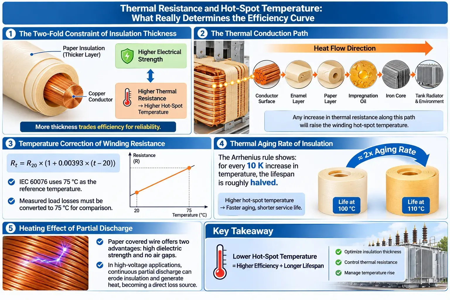
Insulation thickness here exhibits a typical two-way constraint: increasing thickness improves electrical strength, but simultaneously increases thermal resistance and raises hotspot temperatures. The direct consequences of increased thermal resistance are increased conductor temperature, increased resistance, and increased load losses, essentially trading efficiency for reliability. This trade-off must be clearly defined in engineering.
The Thermal Conduction Path
The heat conduction path for paper covered wire to reach thermal equilibrium is: conductor surface, enamel layer, paper layer, impregnation oil, iron core and oil tank radiator, and environment. An increase in thermal resistance at any link in the chain will cause the hot spot temperature to rise. Therefore, paper thickness, impregnation filler density, and thermal conductivity are all efficiency parameters, not just reliability parameters.
Temperature Correction of Winding Resistance
The winding resistance changes linearly with temperature and is calculated using the formula Rₜ = R₂₀ × (1 + 0.00393 × (t − 20)). The IEC 60076 series uses 75 °C as the reference temperature; measured load losses must be converted to this temperature, otherwise loss data between different batches will not be comparable. Loss data outside the same reference temperature are not comparable.
Thermal Aging Rate of Insulation
The thermal aging of insulation materials follows the Arrhenius relation: for every ten Kelvin increase in temperature, the lifespan is roughly halved. This means that efficiency and lifespan are two sides of the same coin in thermal theory: if the hot spot temperature rises due to improper thermal resistance design, the insulation aging rate doubles simultaneously, while winding resistance and load losses increase, resulting in both penalties occurring at the same time.
Heating Effect of Partial Discharge
Paper covered wires offer two advantages in terms of partial discharge: the insulating paper itself has high dielectric strength, and impregnation eliminates internal air gaps. In applications such as high-voltage motor windings and traction transformers, continuous partial discharge can erode the insulation and generate audible noise. Furthermore, the released energy is ultimately converted into heat, constituting a direct source of power loss.
Indirect Efficiency Gains from Electromagnetic and Field Optimization
Potential Distribution at Winding Ends
The electric field strength that the insulation layer withstands depends on the potential distribution between the winding ends and the coil. Uneven voltage distribution between turns can cause local electric field strengths to far exceed the average value.
The principle of capacitive voltage division can be used to uniformly distribute the potential at the ends. Combined with shielding or equalizing rings, peak field strength can be reduced to within the design margin. For high voltage levels and above, the impact of winding end structure design on efficiency is often no less significant than that of conductor cross-section selection.
Mechanical Stiffness of the Winding
The mechanical enhancement provided by paper insulation is easily underestimated. The force that the winding withstands under short-circuit impact is several times that of the electromagnetic force. Winding deformation can lead to inter turn short circuits and partial discharges, thus affecting efficiency. Reliable mechanical stiffness is a prerequisite for maintaining design efficiency in the long term.
Suppressing Stray Loss
stray losses are generated by eddy currents induced in various parts of the winding (tank, clamps, busbars) by leakage flux. These losses can be effectively reduced by optimizing clamp insulation and minimizing circulating current paths in the metal structure. For large-capacity transformers, stray losses constitute a significant portion of the total load losses.
Transposition and Suppressing the Skin Effect
The skin effect causes uneven current distribution across the conductor’s cross-section, resulting in an actual effective cross sectional area that is smaller than the nominal cross sectional area, thus increasing resistance. transposition, by periodically moving the conductor within the slot, averages out the skin effect along the winding length, thereby restoring the effective cross sectional area.
Turn Spacing and Leakage Reactance Consistency
The inter turn spacing affects the leakage magnetic field distribution, which in turn affects the leakage reactance. Changes in leakage reactance will cause changes in load loss and voltage regulation. The consistency of the inter turn spacing in multilayer windings depends on the consistency of the paper layer thickness in paper covered wire systems, which is another basis for the aforementioned thickness tolerance management.
Selection and Implementation: A Practical Path to Higher Efficiency
Decomposing the Loss Budget
The starting point is decomposition. After obtaining the target transformer specifications, first decompose the total loss into P₀ and Pₖ, then decompose Pₖ into three terms: winding DC resistance, eddy currents, and stray currents. The effect of the paper covered wire falls on whichever term, and that’s where you begin.
Checking Conductor Section Against Insulation Occupancy
Check the relationship between conductor cross sectional area and insulation occupancy ratio. The thicker the insulation layer, the smaller the usable conductor cross-section, and the higher the winding resistance.
There is a common engineering misconception here: taking “meeting the insulation strength standard” as the end result. In reality, there is still room for optimization after meeting the standard. Reducing the insulation thickness while meeting the breakdown voltage and creepage distance requirements is a direct way to improve efficiency.
Controlling Moisture Content and Impregnation Quality
Controlling the moisture content and impregnation quality during the process is crucial, as both are direct inputs to dielectric loss and partial discharge. A feasible method for rapid on-site testing is to take a sample, wind it around a needle to form a coil, heat it in an oven, and then measure the insulation resistance. The specific threshold should be determined based on the product test method referenced.
Checking Mechanical Performance Margins
Check the mechanical performance margin. The mechanical loads that paper covered wires bear vary at each stage of winding, slotting, pressing, and fastening. Insufficient margin can create hidden dangers during the assembly stage.
Matching the Insulation Class
Match the insulation class. The thermal class cannot be downgraded. When using high-temperature grade paper covered wire as a low-temperature grade wire, even if the temperature rise margin seems sufficient, the insulation aging rate will already exceed the budget.
Copper Loss and Geometric Consistency
Pay attention to the consistency of copper losses and geometry. If the winding geometry of transformers in the same batch is poor, the dispersion of measured load losses will be significantly amplified. The efficiency gains from geometric consistency are reflected in the average value of the entire batch, rather than in a single exceptionally good sample.
Verifying Efficiency Achievement
Verify the efficiency achieved. The three-phase imbalance of the winding DC resistance should be controlled within the specified limits, and the insulation resistance should be higher than the corresponding threshold. Observe the temperature rise change after running under no-load for a period of time. These are verifications at the winding level.
Risk-Based Sampling
Sampling plans should be determined based on risk classification. Stricter sampling should be applied to critical processes (drying, impregnation, winding), while more lenient sampling may be applied to routine processes. IEC 2859’s AQL sampling rules provide a basic statistical framework, but sampling plans should be determined according to the severity of the consequences of failure.
Typical Applications
Oil-Immersed Distribution Transformers
In oil immersed transformers, paper covered wire and mineral oil form a composite insulation system. The paper layer provides mechanical strength and creepage distance, while the oil provides dielectric strength and heat dissipation channels. The hygroscopic nature of the paper necessitates thorough vacuum drying before winding. In such applications, the core of efficiency design lies in the coordinated control of winding geometry and impregnation quality, rather than single-parameter optimization.
Dry-Type Transformers and the VPI System
Dry type transformers use VPI (vacuum pressure impregnation) resin, which allows the paper covered wire to withstand higher temperature ratings and has more stringent mechanical strength requirements. Since the resin system lacks the oil-penetrating self healing properties of cellulose, the air gap control and impregnation quality of the insulation system become key variables determining long-term reliability.
High-Voltage Motor Windings
High-voltage motor windings are typically covered with mica or modified aromatic polyamide paper, along with a suitable varnish system to withstand electrochemical and thermal aging. Under these conditions, partial discharge is the main cause of efficiency degradation, and the design of the winding end potential distribution and inter turn insulation directly determines the long-term efficiency retention capability.
Traction and Specialty Transformers
Traction transformers are subjected to vibration, shock, and frequent overvoltage conditions, making the mechanical stiffness of the windings and the fatigue resistance of the inter turn insulation the primary considerations in selection. The mechanical reinforcement provided by paper insulation is more valuable than that of conventional stationary equipment in such conditions.
Failure Modes and Directions for Improvement
Moisture Absorption Causing Dielectric Loss Deterioration
Improper control of the drying and impregnation processes can directly increase tan δ and decrease the partial discharge initiation voltage, manifesting as a slow deterioration in efficiency rather than a sudden failure. Improvement should focus on incorporating moisture content and impregnation quality into process control indicators and maintaining traceable records.
Insufficient Overlap Causing Partial Discharge
A lower overlap ratio than the standard requirement will result in insufficient creepage distance, leading to partial discharge at the winding ends or beginning/end areas. The improvement direction is to set a lower limit for the overlap ratio according to the voltage level and implement online monitoring during the winding process.
Breakdown Caused by Insulation Aging
Exceeding the budgeted thermal aging rate will lead to degradation of the coating-paper interface, potentially resulting in breakdown. The improvement lies in calculating thermal life based on hot spot temperatures rather than average temperature rise, while allowing sufficient margin for error.
Loss Dispersion Caused by Geometric Inconsistency
Uncontrolled paper thickness tolerance can cause geometric discrepancies in windings within the same batch, significantly worsening the batch consistency of measured load losses. The improvement direction is to establish a tiered control system for thickness tolerances and incorporate tolerance data into incoming material inspection and winding records.
Standards Relevant to Efficiency
Magnet Wire Specifications and Test Methods
The IEC 60317 series specifies the requirements for enameled wires and assemblies of enameled wires with paper insulation. IEC 60317-0-1 provides general requirements, and its subsections list detailed specifications for paper covered round wire, paper covered flat wire, etc.
The IEC 60851 series comprises test methods for enameled wires, covering breakdown voltage, flexibility, adhesion, thermal shock, and scrape strength. The efficiency-related properties of paper covered wires must ultimately be verified through the corresponding clauses of these test methods.
The Comprehensive Magnet Wire Standard
ANSI/NEMA MW 1000-2018 is the North American standard for magnetic wires, with several volumes covering paper covered round and flat wires, as well as rectangular and square copper and aluminum wires insulated with aromatic polyamide paper, for different temperature grades.
Transformer Efficiency and Loss Classification
IEC 60076-1 specifies the method for calculating transformer efficiency and classifying losses, while IEC 60076-20 specifies the losses and efficiency of power transformers. GB/T 1094.1 and GB/T 10579 are the corresponding domestic standards. Therefore, efficiency indicators are not arbitrary but must fall within the measurement and calculation scope defined by the standards.
The Corresponding Domestic Standard System
GB/T 4074 specifies the basic requirements for winding wires, GB/T 11021 specifies the technical requirements for enameled wires, GB 755 corresponds to IEC 60034-1 for rotating electrical machines, and GB/T 1094 corresponds to IEC 60076 for transformers.
Certification and Market Access
UL 1446 insulation system certification, EN 60317 (equivalent to IEC 60317), JIS C 3202 (Japanese standard for magnetic and paper covered wires), and IEC 2859’s AQL sampling rules together constitute the actual market entry threshold.
Verification Requirements for the Finished Insulation State
Finished product verification needs to be emphasized separately: IEC 60851-3 has specific verification requirements for the insulation condition of finished enameled wires, and mechanical properties and scratch strength must be confirmed batch by batch. The reliability of the insulation system ultimately depends on the condition of the winding after completion, not the condition of individual wires at the time of manufacture.
Conclusion: Efficiency Is Decided Early, Not Adjusted Late
Returning to the initial question: paper covered wire improves electrical efficiency by relying on the simultaneous action of four factors. The winding geometry determines the DC resistance, the paper insulation system determines the dielectric loss, the thermal resistance characteristics determine the hot spot temperature, and the electric field and mechanical design determine partial discharge and stray losses.
Paper covered wire is not an added benefit to efficiency; rather, it is the carrier of efficiency design. Only after the conductor is covered with a layer of paper can the windings have the freedom to be finely designed, and this freedom is the source of efficiency.
At the execution level, the path can be summarized in five steps: Loss budget decomposition to determine which loss category the paper covered wire is affected by; Geometric and insulation occupancy verification to optimize the conductor cross sectional area ratio while meeting breakdown voltage and creepage distance requirements; Moisture content and impregnation quality control to ensure that dielectric loss and partial discharge do not deteriorate; Thermal resistance and temperature margin calculation to ensure that efficiency and lifespan are thermally compatible; and Standard clause verification to ensure that each indicator is traceable.
Efficiency is not a parameter that is tuned at the end; it is determined in a series of early decisions.
The cost of these decisions is often far lower than the rework caused by a single instance of inefficiency.