


Copper Wire Diameter Selection in Transformer Design Engineering Practice Many people think diameter selection is a math problem. Given the current, divide by 2.5 A/mm², and the wire diameter is the answer. Is it really that simple? After six years of experience selecting transformer winding wires, I can tell you: far from it. The wire diameter parameter has far-reaching consequences—increasing it slightly reduces copper losses, but it can cause the fill window to burst, temperature rise to exceed limits, and costs to double; decreasing it slightly reduces costs, but the insulation thickness remains the same, meaning the overall outer diameter isn’t reduced much, and heat dissipation worsens. Diameter selection isn’t a simple current division; it’s an engineering problem of balancing eight engineering parameters. As the core conductor of oil-immersed transformers above 110 kV, the winding diameter of paper-covered copper wire directly determines the transformer’s power density, temperature rise, impedance, and short-circuit withstand capability. This article systematically explains diameter selection methods, standard systems, performance trade-offs, application scenarios, and a 5-step decision-making process from an engineering practice perspective—after reading, you should be able to independently select the appropriate conductor for different transformer operating conditions. ##
Diameter Parameter System for Paper-Sheathed Copper Wire In engineering, diameter is not just a single number. The “diameter” of paper-sheathed copper wire is actually a 5-dimensional parameter system—conductor diameter, maximum outer diameter after insulation paper tape wrapping, sheathing layer increment, roundness deviation, and conductor tolerance.
Conductor Diameter and Tolerances Paper-sheathed copper wire conductors come in two forms: round copper and flat copper. Round copper wire (NEMA MW 31/33) tolerances are as follows according to IEC 60317-29: Below 0.50 mm, tolerance ±0.005 mm; 0.50-1.00 mm, tolerance ±0.010 mm; 1.00-2.50 mm, tolerance ±0.015 mm. The thickness tolerance for rectangular copper wire is more stringent because insulation matching in the thickness direction directly determines the withstand voltage—the thickness tolerance is typically ±0.030 mm for flat wires with a thickness of 1.00-3.00 mm, and ±0.050 mm for widths of 5.00-15.00 mm. NEMA MW 1000-2018 MW 33 series specifically specifies the dimensional tolerances for this type of rectangular paper-insulated copper wire.
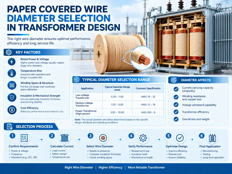
Increment in Insulation Tape Among the diameter parameters of paper-insulated copper wire, the most easily overlooked is the “increase in dimensions.” This is the difference between the outer diameter of the conductor and the outer diameter of the guide body. The overlay increment is determined by the thickness and overlap rate of the insulating paper tape:
| Paper Tape Type | Typical Layers | Single Layer Thickness | Overlay Rate | Total Increment (Single Side) |
|---|---|---|---|---|
| Cable Paper Tape | 2-4 layers | 0.10-0.17 mm | 30-50% | 0.20-0.68 mm |
| Telephone Paper Tape | 3-5 layers | 0.05-0.08 mm | 50-70% | 0.15-0.56 mm |
| Nomex Aromatic Polyamide Paper Tape | 1-3 layers | 0.25-0.50 mm | 40-60% | 0.50-1.50 mm |
| Polyimide Film Composite Paper Tape | 2-3 layers | 0.10-0.20 mm | 50% | 0.20-0.60 mm |
Typical Sheathing Layer Increment of Paper Covered Copper Wire
Note a detail here—the thickness of the cable sheath directly determines the transformer insulation class. 0.10 mm cable paper, 2 layers stacked, 0.20 mm increment per side, corresponds to IEEE C57.12.00 Class A 105°C oil immersion; 0.17 mm cable paper, 4 layers stacked, 0.68 mm increment per side, corresponds to Class B 130°C high oil temperature scenario. This increment is the primary parameter calculated by engineers when selecting a cable—it directly determines the winding outer diameter and window utilization. ###
Relationship between Breakdown Voltage and Diameter For every 0.10 mm increase in sheath thickness, the breakdown voltage increases by approximately 300-500 V (oil immersion condition). NEMA MW 1000-2018 MW 60-A specifies that the dielectric breakdown of the aromatic polyamide paper-coated layer should be ≥ 300 V/mil (11800 V/mm). Based on this ratio, a 110 kV transformer high-voltage winding requires at least 6-8 mm of total insulation (paper sheath + oil gap + barrier), corresponding to a conductor outer diameter of 8-12 mm. This is a typical application of insulation design derived from diameter. ##
Engineering Significance of Diameter Selection Why is diameter selection so important? Because it is not just a matter of copper resistance, but a compromise point for all operating conditions of the transformer. ###
Current Density Method (The Most Basic Method) The current density method is the most commonly used method for initial diameter selection in engineering—first determine the current density J, then calculate the diameter: d = √(4I / πJ) where d is the conductor diameter (mm), I is the rated current (A), and J is the current density (A/mm²). IEEE C57.12.00 specifies a typical current density of 2.5 A/mm² for oil-immersed transformers and 1.5-3 A/mm² for dry-type transformers—these are engineering empirical values, not physical limits. For example, a 110 kV / 630 kVA distribution transformer with a low-voltage winding current of approximately 900 A, calculated at J = 2.5 A/mm², requires a total conductor cross-sectional area of 360 mm²—this can be achieved using 21.4 mm diameter round copper, or 10 mm × 6 mm flat copper (60 mm² cross-sectional area) wound with 6 strands. Alternatively, a single 14 mm × 10 mm flat copper strand (140 mm²) wound with 3 strands can also be used. The diameter/cross-sectional area combination is not unique—this is precisely where the complexity of diameter selection lies. ###
Temperature Rise Method (Core Method for Oil-Immersed Transformers) The thermal limit of oil-immersed transformers is not that of enameled wire, but rather the composite system of insulating paper and transformer oil. IEEE C57.91 specifies a hot spot temperature rise of 65-78 K for oil-immersed transformers—meaning the winding temperature can be up to 78°C higher than the ambient temperature. Diameter selection must meet this constraint. The core formula of the temperature rise method is a simplified engineering version of Newton’s law of cooling: ΔT = P × R_th, where ΔT is the temperature rise (K), P is the winding loss (W), and R_th is the thermal resistance (K/W). The winding loss P = I² × R (R is the DC resistance), and the thermal resistance R_th is determined by the insulation layer thickness and oil flow rate. For oil-immersed windings, the empirical value of R_th is 0.05-0.15 K/W; for dry windings (natural cooling), the empirical value of R_th is 0.5-1.5 K/W. Based on a temperature rise limit of 78 K and a thermal resistance of 0.10 K/W, the maximum allowable loss for a single-phase winding is 780 W. If the single-phase winding has 100 turns and a current of 900 A, then the single-phase resistance is 0.001 Ω (based on the resistivity of aluminum) – using R = ρL/A, the conductor cross-sectional area is calculated to be 8.4 mm² (diameter 3.3 mm). The diameter calculated using the temperature rise method is usually larger than that calculated using the current density method – this is why the actual wire diameter used in oil-immersed transformer high-voltage windings is often larger than the initial value selected using the current density method. ###
Fill Factor Method (Core of Winding Design) The fill factor is a parameter that directly determines the size and cost of the transformer in winding design. It is defined as: K_f = total conductor cross-sectional area / winding window area. The typical fill factor for oil-immersed transformer round copper windings is 0.55-0.65, and for flat copper windings it is typically 0.75-0.85. Flat copper has a 30-50% higher fill factor than round copper—this is why all high-power transformers above 110 kV use flat copper windings. The fill factor method is directly linked to diameter selection—increasing the diameter (thickness) increases the conductor cross-sectional area, but simultaneously the number of turns per layer of winding decreases, while the total number of layers increases—the change in fill factor is non-linear. In engineering, empirical curves are generally used:
| Flat Copper Thickness (mm) | Typical Fill Factor | Applicable Scenarios |
|---|---|---|
| 1.00-1.50 | 0.70-0.75 | Small transformers, low-voltage windings |
| 1.50-2.50 | 0.75-0.82 | Medium transformers, distribution transformers |
| 2.50-4.00 | 0.82-0.88 | Large transformers, high-voltage windings |
| 4.00-6.00 | 0.85-0.90 | Power transformers, ultra-high voltage |
Table 2: Relationship Between Flat Copper Thickness and Fill Factor
Impedance matching method (short-circuit impedance design) Short-circuit impedance is a key parameter for transformers operating in parallel. The short-circuit impedance Z_k% is mainly determined by the leakage reactance X_k, which is calculated using the formula: X_k = 2πf × μ₀ × N² × S / h, where f is the frequency (Hz), μ₀ is the free permeability, N is the number of turns, S is the leakage magnetic area, and h is the winding height. Decrease in diameter → Increase in number of turns → Increase in N² → Significant increase in X_k—this is why high-current windings must use thicker diameter/wider conductors. A typical short-circuit impedance of 110 kV 100 MVA transformer is 12-15%, corresponding to a high-voltage winding that must use flat copper with a thickness ≥ 2.5 mm, a width ≤ 25 mm, and a turn count controlled between 800-1200 turns. Choosing a diameter (thickness) 1 mm smaller will increase the number of turns by 20-30%—resistance will exceed 18%. This illustrates the engineering sensitivity of diameter selection. ##
Detailed Explanation of Standards System The selection of the diameter of paper-insulated copper wire must strictly adhere to international standards; otherwise, problems will arise in insulation matching, factory testing, and export certification. ###
IEC 60317-29 (International Electrotechnical Commission) IEC 60317-29 is the most core international standard for paper-insulated copper wire. It specifies: – Conductor diameter range: 0.50-5.00 mm round copper / thickness 0.80-10.00 mm × width 2.00-25.00 mm flat copper – Sheath type: cable paper (Class A 105°C), telephone paper (Class A), Nomex paper (Class H 180°C / Class C 220°C), polyimide paper (Class C 240°C) – Number of sheath layers: 1-6 layers (increasing according to voltage level) – Sheath overlap: 30-50% / 40-60% / 50-70% – Test methods: breakdown voltage, elongation, bending test, adhesion. IEC 60317-29 is a mandatory standard for export to Europe, Southeast Asia, and the Middle East—when selecting a conductor, first determine the conductor specifications and sheath structure according to IEC 60317-29. ###
NEMA MW 1000 (US Standard) NEMA MW 1000-2018 is a mandatory standard for the North American market. It categorizes paper-sheathed copper wire into the following models:
| NEMA Model | Conductor | Sheathing Material | Thermal Class | Typical Applications |
|---|---|---|---|---|
| MW 31 | Round copper | Cable paper | 90/105°C | Small oil-immersed transformer |
| MW 33 | Flat copper | Cable paper | 105/130°C | Power distribution transformer |
| MW 60-A | Round/flat aluminum | Aromatic polyamide paper | 220°C | High temperature transformer |
| MW 61 | Round/flat aluminum | Aromatic polyamide paper | 240°C | Special high temperature transformer |
| MW 64 | Round/flat copper | Polyimide tape | 240°C | Aerospace transformer |
| MW 65 | Round/Flat Aluminum | Polyimide Tape | 240°C | Aerospace Transformer |
Table 3: NEMA MW 1000-2018 Paper-Sheathed Copper Wire Models System
North American customers’ transformer projects must use one of NEMA MW 31/33/60/61/64/65—without exceptions. This must be confirmed first during the selection process.
GB/T 7672 (Chinese National Standard) GB/T 7672 is a Chinese natnal standard, equivalent to IEC 60317-29. Major domestic transformer manufacturers (TBEA, Mingyang Electric, ABB China) organize production according to GB/T 7672. However, export projects cannot directly use GB/T 7672—they must switch to IEC 60317-29 or NEMA MW 1000 based on the customer/target market.
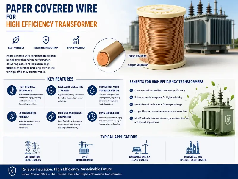
Standard Selection Recommendations
| Project Type | Standard Selection Priority |
|---|---|
| Domestic Transformer Projects | GB/T 7672 > IEC 60317-29 |
| Export to Europe/Middle East/Southeast Asia | IEC 60317-29 > GB/T 7672 |
| Export to North America | NEMA MW 31/33/60/61/64/65 |
| High Temperature Special Transformers (Aerospace/Nuclear Power) | NEMA MW 64/65 > IEC 60317-29 |
| High Voltage/Ultra-High Voltage Power Transformers | IEC 60317-29 + IEEE C57.12.00 Dual Standards |
Table 4: Standard Selection Priority
Diameter-Performance Trade-off Parameter Table Below is a diameter-performance trade-off parameter table for 18 commonly used paper-insulated copper wire specifications in engineering—directly refer to it during selection:
| Specification | Conductor Diameter/Thickness (mm) | Cross-sectional Area (mm²) | Max Outer Diameter (mm) | Resistance (Ω/km @20°C) | Applicable Current (A @J=2.5) | Breakdown Voltage (kV) | Typical Application |
|---|---|---|---|---|---|---|---|
| Round Copper MW 31-1.0 | 1.00 | 0.785 | 1.40 | 22.40 | 1.96 | 3.0 | Small Low-Voltage Winding |
| Round Copper MW 31-2.0 | 2.00 | 3.14 | 2.68 | 5.60 | 7.85 | 5.0 | Small Transformer |
| Round Copper MW 31-3.0 | 3.00 | 7.07 | 4.00 | 2.49 | 17.7 | 6.5 | Power Distribution Transformer |
| Round Copper MW 31-5.0 | 5.00 | 19.63 | 6.36 | 0.90 | 49.1 | 8.5 | Large Oil-Immersed |
| Flat Copper MW 33-1.6×5 | 1.60×5.00 | 8.00 | 6.20 × 2.80 | 2.20 | 20.0 | 4.0 | Medium Voltage Winding |
| Flat Copper MW 33-2.0×6 | 2.00×6.00 | 12.00 | 7.40 × 3.40 | 1.47 | 30.0 | 5.0 | Medium Transformer |
| Flat Copper MW 33-2.5×8 | 2.50×8.00 | 20.00 | 9.70 × 4.20 | 0.88 | 50.0 | 6.0 | Power Distribution Transformer |
| Flat Copper MW 33-3.0×10 | 3.00×10.00 | 30.00 | 11.90 × 4.90 | 0.59 | 75.0 | 7.0 | Large Transformer |
| Flat Copper MW 33-3.5×12 | 3.50×12.00 | 42.00 | 14.10 × 5.60 | 0.42 | 105.0 | 8.0 | High Voltage Winding |
| Flat Copper MW 33-4.0×14 | 4.00×14.00 | 56.00 | 16.20 × 6.20 | 0.31 | 140.0 | 9.0 | Power Transformer |
| Flat Copper MW 33-5.0×18 | 5.00×18.00 | 90.00 | 20.40 × 7.40 | 0.20 | 225.0 | 10.0 | Large Power Transformer |
| Nomex Package MW 60-A 2.0 | 2.00 | 3.14 | 3.60 | 5.60 | 7.85 | 12.0 | High Temperature Oil Immersion |
| Nomex Package MW 60-A 3.0 | 3.00 | 7.07 | 4.80 | 2.49 | 17.7 | 15.0 | High Temperature Special |
| Nomex Package MW 60-A 5.0 | 5.00 | 19.63 | 7.20 | 0.90 | 49.1 | 18.0 | Nuclear Power Transformer |
| Round Copper MW 64-2.0 (Polyimide Tape) | 2.00 | 3.14 | 2.80 | 5.60 | 7.85 | 16.0 | Aerospace Transformer |
| Round Copper MW 64-3.0 (Polyimide Tape) | 3.00 | 7.07 | 4.00 | 2.49 | 15.2 | 20.0 | Aerospace Transformer |
| Flat Copper Polyimide 1.5×8 | 1.50×8.00 | 12.00 | 9.40 × 2.90 | 1.47 | 26.0 | 14.0 | High Frequency Transformer |
| Flat Copper Polyimide 2.5×12 | 2.50×12.00 | 30.00 | 13.80 × 4.30 | 0.59 | 65.0 | 17.0 | UHV Dry Transformer |
Table 5: Parameter Comparison Table of Common Paper-Sheathed Copper Wire Specifications
Note several key observations: – For the same cross-sectional area, the maximum outer diameter of flat copper is 10-15% smaller than that of round copper—this is why high-voltage windings use flat copper exclusively. – For the same conductor, the minimum resistivity of Nomex sheathing is 5-8% lower—this is because Nomex has a larger thickness but higher temperature resistance. – The breakdown voltage is not linear with the cross-sectional area—it is mainly determined by the thickness of the insulation layer. ##
Application Scenarios Comparison
110 kV and Above Oil-Immersed Transformers 110 kV and above oil-immersed transformers are the main battleground for paper-sheathed copper wire. All 110 kV, 220 kV, 500 kV, and 1000 kV ultra-high voltage power lines use paper-insulated copper wire. There are three reasons for this: First, the composite system of insulating paper and transformer oil has a long lifespan—the insulating paper can operate stably in oil for 30-50 years, twice as long as enameled wire. Second, oil has high cooling efficiency—transformer oil has a much higher specific heat capacity and thermal conductivity than air, making the heat dissipation efficiency of oil-immersed windings 5-10 times higher than that of dry-type windings. Third, the diameter selection is flexible—oil-immersed windings can use thick-diameter round copper (maximum 6 mm) or large-size flat copper (6 mm thick × 25 mm wide), while dry-type windings cannot use such thick wires due to heat dissipation limitations. Typical selections: 110 kV high-voltage windings use MW 33 flat copper 3.0×10 mm to 4.0×14 mm; 220 kV high-voltage windings use MW 33 flat copper 4.0×14 mm to 5.0×18 mm; 500 kV uses polyimide film composite paper sheathing 5.0×18 mm or thicker special specifications. ###
Distribution Transformer (10-35 kV) Distribution transformers (10-35 kV) are the second largest application scenario for paper-sheathed copper wire. Unlike high-voltage power transformers, distribution transformers have lower voltage levels, smaller capacities (50-2500 kVA), and higher current densities (3-4 A/mm²)—cost is a primary consideration when selecting them. Typical selection: For 10 kV distribution transformers, high-voltage windings use MW 31 round copper (1.6-3.0 mm) or MW 33 flat copper (1.6×5 mm to 2.5×8 mm); low-voltage windings (400 V) with high current use flat copper (5.0×18 mm to 10.0×25 mm) wound in parallel. ###
Dry-type transformers (epoxy/resin casting) Dry-type transformers (H class and above) are not suitable for paper-insulated copper wire—because paper insulation contains moisture, and long-term operation in air will lead to increased dielectric loss and decreased insulation strength. However, there is an exception—Nomex paper-insulated copper wire can be used in high-temperature applications (180-220°C) with dry-type transformers. Typical selection: Nomex dry-type transformer with copper wire 2.0×6 mm to 3.5×12 mm, mainly used for high-voltage windings of H-class (180°C) dry-type transformers. ### Specialty Transformers Specialty transformers include: – Medical Transformers (MRI, CT, X-ray machines): MW 64 polyimide-coated copper wire, high temperature resistance 240°C, good mechanical stability. – Railway Traction Transformers: Nomex paper-coated (220°C) + mineral oil, resistant to temperature shock from -40°C to +70°C. – Wind Power Transformers: MW 60-A 220°C high temperature resistance paper-coated copper wire, matching the high-frequency operating conditions of wind power converters. – Photovoltaic Inverter Transformers: Polyimide film paper-coated copper wire, low high-frequency loss. ###
New Energy Vehicle Transformers (30-100 kW) are an emerging application scenario. The frequency is higher than the power frequency (1-10 kHz), requiring paper-insulated copper wire with high high-frequency resistance. Typical selection: polyimide film paper-insulated flat copper wire 1.5×8 mm to 2.5×12 mm, matching the miniaturized design of high-frequency transformers.
Diameter Selection 5-Step Decision Process The diameter selection of paper-insulated copper wire is not solved by a single formula—it involves 5 engineering judgment steps. Below is the commonly used 5-step decision process in engineering.
Step 1: Assess the Application Environment The application environment is the first constraint on diameter selection. Clarify three questions: – Oil immersion or dry? Oil immersion → Any paper-insulated model can be used; Dry → Must use Nomex wrapping or polyimide tape wrapping. – Room temperature or high temperature? Ambient temperature (≤ 105°C) → Cable paper sheath; High temperature (180-220°C) → Nomex sheath; Ultra-high temperature (240°C) → Polyimide tape sheath – Stationary or vibrating? Stationary (transformer) → Any; Vibrating (motor/traction) → Preferred flat copper, vibration resistant ###
Step 2: Calculate rated current and voltage Calculate winding current and voltage according to transformer capacity and voltage: I = S / (√3 × U) (three-phase) I = S / U (single-phase) 110 kV 10 MVA transformer high voltage winding current is about 52 A, calculated according to J = 2.5 A/mm², a cross-sectional area of 21 mm² is required – use 5.0 mm diameter round copper or 2.0 × 12 mm flat copper. ###
Step 3: Initial Diameter and Sheathing Specifications Initially select the diameter using the current density method, then fill in the sheathing specifications using the temperature rise method: – Oil immersion at room temperature → 2-4 layers of cable paper sheath, conductor +0.40-0.80 mm increment – Oil immersion at high temperature → 2-3 layers of Nomex sheath, conductor +0.50-1.20 mm increment – Dry sheath at high temperature → 2-3 layers of polyimide tape sheath, conductor +0.20-0.60 mm increment ###
Step 4: Fill Factor and Impedance Verification Calculate the fill factor and short-circuit impedance based on the initially selected diameter: – Fill factor > 0.85 → Further optimization (increase the number of turns or reduce the diameter) – Fill factor < 0.70 → Consider reducing the diameter or replacing the copper/aluminum conductor – Short-circuit impedance exceeds limits → Adjust the number of turns or reselect the type ###
Step 5: Verification and Sample Testing Sample verification is the final hurdle in diameter selection: – Breakdown voltage test (according to IEC 60317-29 / NEMA MW 1000) – Oil immersion withstand voltage test (according to IEEE C57.91) – Temperature rise test (6 hours under full load, hot spot temperature ≤ 78 K) – Bending test (according to NEMA MW 60-A 6 × bare wire thickness) – Short circuit withstand test (25 kA / 2 seconds) ###
Diameter Selection Quick Reference Table
| Key Parameters | Option 1: Cable Paper Sheath (MW 31/33) | Option 2: Nomex Sheath (MW 60-A/61) | Option 3: Polyimide Tape Sheath (MW 64/65) |
|---|---|---|---|
| Applicable Scenarios | Oil immersion at room temperature (≤ 130°C) | Oil immersion at high temperature (180-220°C) | Dry-type ultra-high temperature (240°C) |
| Thermal Class | 90/130°C | 220°C | 240°C |
| Number of Coating Layers | 2-4 layers | 1-3 layers | 1-3 layers |
| Single-Sided Increment | 0.20-0.68 mm | 0.50-1.50 mm | 0.20-0.60 mm |
| Breakdown Voltage | 3-10 kV | 12-18 kV | 14-20 kV |
| Fill Factor | 0.70-0.85 | 0.65-0.80 | 0.65-0.80 |
| Procurement Convenience | High (mature supply chain) | Medium (specialty supplier) | Medium (aerospace supplier) |
| Typical Application | 110 kV oil immersion | High temperature special | Aviation/Aerospace |
Table 6: Quick Reference Table for Paper-Sheathed Copper Wire Diameter Selection ##
Summary
Diameter selection is not a math problem, but an engineering problem—a comprehensive balance of 8 parameters (current density, temperature rise, fill factor, impedance, insulation class, short-circuit withstand, procurement cost, and long-term reliability).
From an engineering practice perspective, there are five core conclusions regarding diameter selection. First, diameter selection must be strictly implemented according to the standard system (IEC 60317-29 + NEMA MW 1000-2018)—this is especially important for export projects. Second, the current density method is only a preliminary selection—the comprehensive verification using the temperature rise method, fill factor method, and impedance matching method is the core of engineering. Third, flat copper has a 30-50% higher fill factor than round copper—high-power transformers must use flat copper windings. Fourth, the cladding layer increment is the main determinant of the winding outer diameter—the conductor diameter and insulation thickness must be calculated simultaneously during selection. Fifth, sample verification is indispensable—breakdown testing, temperature rise testing, and bending testing are hard constraints on design dimensions. From a market perspective, new energy vehicles (30-100 kW high-frequency), wind power (220°C high-temperature), and ultra-high-voltage power (500 kV+) are the three most popular application scenarios for diameter selection. These three scenarios require 1-2 orders of magnitude higher precision in diameter selection than traditional power distribution transformers. From a supply chain perspective, international suppliers of paper-clad copper wire are highly concentrated—North America (Essex, Furman, Magnetix USA, Phelps Dodge), Europe (ABB, Siemens), and China (Zhengzhou LP Industry, Tongling Jingda) are the three major clusters. Chinese manufacturers are rapidly expanding their production capacity in flat copper, Nomex-clad, and polyimide tape-clad applications. LP Industry, a 30-year veteran in the wire industry exporter, covers four major standard systems: NEMA, IEC, GB/T, and JIS, offering a full range of specifications for round copper (0.50-5.00 mm) and flat copper (0.80-6.00 mm thick × 2.00-25.00 mm wide). Multiple sheathing options are available, including Nomex sheathing, polyimide tape sheathing, and cable paper sheathing. From design selection to sample verification, LP provides complete technical support—after all, diameter selection cannot be solved simply by looking at a parameter table; it requires engineers with a deep understanding of standards, materials, processes, and testing. Finally, a key lesson from engineering practice is emphasized: diameter selection is not a one-step process. A complete selection cycle typically takes 4-6 weeks—including standard confirmation, initial specification selection, sample preparation, breakdown testing, temperature rise testing, and impedance verification. There are no shortcuts. This is engineering.