

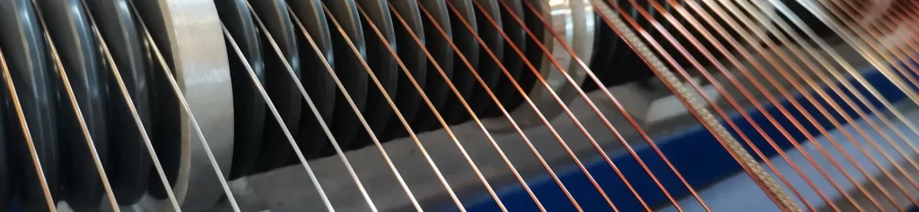
What Ultra-Fine Enameled Wire Is: Definition and Diameter Segmentation
Ultra-Fine Is Not a Standardized Term
In the enameled wire industry, “ultra-fine” is not a standard term, but rather a range of terms. It refers to the section of product where the diameter of the bare copper conductor is significantly smaller than the lower limit of the standard enameled wire. The manufacturing starting point for conventional enameled copper wire is 0.016 mm. IEC 60317-51 specifies that the nominal conductor diameter range for Grade 1 enamel coating of solderable polyurethane enameled round copper wire (Class 180) is from 0.018 mm to 1.000 mm (inclusive). In practical procurement contexts, the 0.018 mm to 0.050 mm range is typically referred to as ultra-fine or micro-fine wire, while the 0.050 mm to 0.100 mm range is the transition zone for conventional fine wire.
Diameter Segmentation and Typical Uses
According to this classification, the 0.018 to 0.030 mm range is considered the ultra-fine section, mainly used for extremely small transducers and instrument components, with the highest manufacturing difficulty and inspection cost; the 0.030 to 0.050 mm range is the ultra-fine main section, where voice coils, precision instrument windings, small relays, and micro motor windings mostly fall into this category; and the 0.050 to 0.100 mm range is the transition section, striking a balance between cost and manufacturing difficulty.
Why Reducing Wire Diameter Changes the Nature of the Problem
What truly makes this line segment a separate topic is not the line diameter itself, but rather the fact that a series of proportional relationships are simultaneously altered after the line diameter is reduced.
| Nominal Conductor Diameter | Class 3 Total Diameter | Class 9 Total Diameter | Enamel Share of Diameter (Class 3) | Enamel Share of Diameter (Class 9) |
|---|---|---|---|---|
| 0.040 mm | 0.055 to 0.070 mm | 0.062 to 0.091 mm | 27.3% to 42.9% | 35.0% to 55.6% |
| 0.071 mm | 0.080 to 0.095 mm | 0.090 to 0.125 mm | 12.7% to 25.3% | 21.1% to 43.2% |
| 0.125 mm | 0.140 to 0.160 mm | 0.155 to 0.200 mm | 12.5% to 21.9% | 19.4% to 37.5% |
| 0.224 mm | 0.250 to 0.280 mm | 0.270 to 0.320 mm | 10.4% to 20.0% | 17.1% to 30.0% |
| 0.400 mm | 0.460 to 0.510 mm | 0.480 to 0.560 mm | 13.0% to 21.6% | 16.7% to 28.6% |
| 0.710 mm | 0.800 to 0.850 mm | 0.820 to 0.920 mm | 11.3% to 17.5% | 13.3% to 22.8% |
The enamel share is derived from the FIW dimension tables as the ratio of the radial coating increment to the total diameter. Values are engineering estimates for trend illustration, not design values. First, let’s look at the resistance. Based on the resistivity of copper at 20 °C (1.68 × 10⁻⁸ Ω·m), the theoretical resistance of a 0.040 mm wire diameter is approximately 13.37 Ω/km. IEC 60317-0-7 specifies resistance limits for defect-free FIW enameled round copper wire with a nominal diameter of 0.040 mm as 12.280 to 14.920 Ω/m, with the difference arising from the deviation between conductor tolerances and actual resistivity. The theoretical resistance of a 0.020 mm wire diameter is approximately 53.48 Ω/km, and that of a 0.018 mm wire is approximately 66.02 Ω/km.
In other words, moving from 0.040 mm to 0.018 mm, the wire diameter only shrinks to 45% of its original size, but the resistance per unit length increases by 4.9 times. Now let’s look at the enamel coating. The enamel coating thickness is an absolute increment specified according to the insulation class, not a proportional value based on the conductor diameter. Taking the dimensions given in the FIW standard as an example, a 0.040 mm conductor with a Class 3 enamel coating has a total diameter of 0.055 to 0.070 mm, with the enamel coating accounting for 27.3% to 42.9% of the diameter; while a 0.400 mm conductor with the same Class 3 enamel coating has a total diameter of 0.460 to 0.510 mm, with the enamel coating accounting for only 13.0% to 21.6%.
This is the most fundamental difference in thinner segments: the enamel coating is no longer a thin layer of additive on the outside of the conductor, but a solid layer occupying nearly one-third to almost half of the diameter. Third is the number of turns. The number of turns in a device coil is determined by both the required magnetic flux and the available window, but reducing the wire diameter will simultaneously compress the available window, forcing the number of turns to increase further. It is common for thin wire windings to have thousands of turns, and the increase in the number of turns directly amplifies the probability of failure of the inter-turn insulation, rather than the current density on the conductor cross-section.
The Scope of This Article
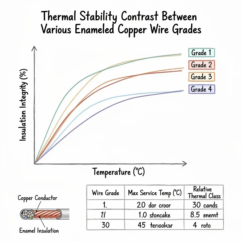
Therefore, the subject of this article can be defined as follows: ultra-fine enameled copper wire device coils refer to windings with bare copper conductors of 0.018 to 0.050 mm as the skeleton, wound on small or micro magnetic cores and skeletons, which are widely found in audio transducers, precision instruments, sensors, relays, micro motors, medical devices and consumer electronics.
Cross-Sectional Constraints from the Enamel Coating Ratio
Redistribution of the Cross-Sectional Area Budget
If the design of thin line segments simply follows the approach of thick lines, the first thing that will fail is the cross-sectional area estimation. Based on a square wire arrangement and a layout factor of 0.55, a 0.040 mm conductor with a Class 3 enamel coating (maximum total diameter 0.070 mm) occupies approximately 18.0% of the winding cross-sectional area; the same wire diameter with a Class 9 enamel coating (maximum total diameter 0.091 mm) occupies only about 10.6%. In contrast, a 0.125 mm conductor with a Class 3 enamel coating (maximum total diameter 0.182 mm) occupies approximately 25.9%. The finer the wire diameter, the faster the effective copper content that can be accommodated within the same window decreases.
Rising Copper Loss Is an Inevitable Consequence
The first consequence is increased copper losses. To carry the same current under a given resistance, more turns and a larger window must be used, rather than simply using thicker wire. Increased copper losses are usually acceptable at the device level because the total power of the device is small; however, it will translate into heat, requiring a trade-off between insulation class and coil size.
Rising Thermal Resistance
The second consequence is increased thermal resistance. The effective heat dissipation surface of a fine-wire winding is determined by its total diameter, not by the conductor diameter. Within the same cross-section, a winding wound with 0.040 mm wire has a significantly smaller external heat dissipation surface area than a winding wound with 0.125 mm wire, while its internal copper volume ratio is lower. This means that fine-wire windings experience a higher temperature rise for the same copper loss, and a margin must be allowed when selecting the thermal rating.
Declining Mechanical Strength
The third consequence is a decrease in mechanical strength. Copper’s tensile strength approaches the material’s upper limit when the cross-sectional area is large enough, but as the cross-sectional area decreases, the influence of work hardening and surface defects increases, and the elongation decreases significantly. As a result, the tension window during winding narrows: excessive tension leads to wire breakage or varnish cracking, while insufficient tension results in poor wiring and short circuits between turns.
Enamel System Selection: UEW as the Primary Choice, with PEW and EIW as Supplements
Three Reasons Polyurethane Dominates
The vast majority of coils for micro-devices use polyurethane (PU/UEW) coatings for three main reasons. First, it offers direct solderability. The polyurethane coating softens and is peeled off by the molten solder within its melting temperature range, allowing the coil leads to be directly soldered without the need for mechanical scraping or chemical stripping. In the fast-paced electronic assembly process, the coating removal process itself is a separate workstation and a burden of managing residues. Secondly, there is the issue of high-frequency dielectric loss. The dielectric constant and dielectric loss tangent of polyurethane are significantly lower than those of polyesterimide and polyimide. In devices operating at audio frequencies and higher switching frequencies, this difference manifests as winding losses and heat distribution. Thirdly, it offers flexible modification options. Polyurethane can improve its thermal properties while maintaining weldability through isocyanate resin modification or composite coating, thus creating a product series with three grades: 130, 155, and 180.
| Thermal Class | Base Coating | Direct Soldering Temperature | Typical Applications |
|---|---|---|---|
| 130 | Modified polyurethane | 375 to 390 °C | Micro motors, small relay coils, low-temperature device coils |
| 155 | Polyurethane-imide | 385 to 400 °C | Precision instrument windings, sensor coils, mini transformer coils |
| 180 | Polyurethane or polyurethane-imide composite | 395 to 410 °C | Loudspeaker voice coils, small high-frequency transformer coils, higher-density device coils |
The soldering temperatures above refer to the bath temperature range in which the coating softens and is stripped by molten solder. The class number defines the thermal rating, not the soldering window.
Limitations of Polyester Enamel in the Fine-Wire Segment
Polyester (PEW) coatings have a narrower application range in ultra-fine wire segments compared to polyurethane, for the same clear reason: PEW lacks direct solderability, and the coating itself has higher hardness and abrasion resistance. In fine wire segments, this translates to an increased risk of coating cracking during winding, and the need for separate coating removal at the leads. PEW’s main advantages lie in its thermal rating and self-adhesive structure. If the device does not require solderability and winding tension is well controlled, PEW remains a viable option.
The Role of Polyester-Imide and Polyamide-Imide
Polyester imide (EIW) and polyamide imide (AIW) coatings are used in high-temperature applications in ultrafine device lines. The official thermal ratings for EIW and AIW are typically 200 to 220 °C, with AIW generally having a softening breakdown temperature above 330 to 350 °C. Under rapid heating and cooling exceeding 200 °C, the internal stress of the coating is extremely low. It is important to clarify that thermal rating and softening breakdown temperature are two different indicators; a rating of 220 does not mean the coating begins to soften at 220 °C.
Enamel Grade: Numeric Grading versus English Grading
The choice of coating grade is equally important. GB/T 6109, IEC 60317, and JIS use numerical grading, with smaller numbers indicating thinner coatings. Grade 1 is a thin coating, Grade 2 is a thick coating (a common benchmark in global industry and trade), and Grade 3 is an extra-thick coating. North America’s NEMA MW 1000 uses English grading: Single Build, Heavy Build, Triple Build, and Quadruple Build. For the same coating base material, different coating grades will result in decisive differences in final outer diameter, breakdown voltage, mechanical abrasion resistance, and winding space occupancy. For ultrafine wires, the cross-sectional area loss is calculated proportionally for each increase in coating grade; therefore, coating grade and wire diameter must be specified as a whole and cannot be decided separately.
Selecting Thermal Class and Temperature Index
Three Factors That Jointly Determine Thermal Class
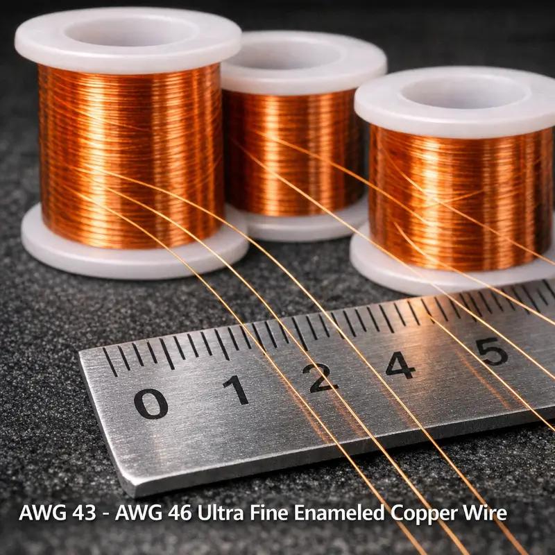
The thermal rating of coils for ultra-fine devices is usually not determined by the operating temperature alone, but by three constraints. The first is the worst-case operating temperature. The ambient temperature inside the device plus the temperature rise of the winding itself constitutes the actual temperature that the enamel film can withstand. The heat resistance design of the enameled wire itself has a certain margin. 130-grade polyurethane enameled wire is widely used in many everyday electronic components. In addition to the process advantages such as the lowest direct soldering temperature and the fastest direct soldering speed, it also largely comes from this margin strategy. Secondly, there is thermal shock. Device coils often undergo repeated cycles from room temperature to operating temperature, especially in applications with cyclical heat loads, such as power modules and drive modules. The tendency of the coating film to crack under sudden cooling and heating is directly related to the toughness of the coating film system. Thirdly, there is the mechanical and thermal stress during the winding and assembly process. The deformation experienced by thin wire windings during winding and subsequent assembly is different from that of thick wire, and the mechanical fatigue resistance of the enamel film is relatively reduced in the thin-walled state.
Temperature Index Is Not the Same as Recommended Operating Temperature
A commonly misunderstood point needs clarification: the Celsius temperature corresponding to the temperature index is not necessarily equal to the recommended operating temperature. The actual operating temperature depends on various factors, including the type of equipment. For example, 120-grade polyvinyl acetal enameled copper wire requires a minimum temperature index of 120 and a thermal shock temperature of at least 155 °C; these are two different assessment criteria.
Solderability and the Soldering Process Window
Direct Soldering Principle and Conventional Parameters
The ability to directly weld thin wire segments is the most easily overestimated feature. The direct soldering principle of solderable polyurethane enameled wire is as follows: the enamel film melts within the solder melting temperature range, is peeled off by the molten solder, and floats to the surface. This process requires a soldering temperature sufficient to melt the enamel film, but the dwell time cannot be too long, otherwise the copper conductor itself will be excessively oxidized or ablated. The direct soldering temperature range for conventional thick wires is usually between 380 and 420 ℃, varying depending on the grade and modified formulation.
Three Reasons the Process Window Narrows in the Fine-Wire Segment
When it comes to ultra-fine lines, the processing window narrows significantly for three reasons. One factor is heat capacity. The thermal mass of a 0.018 mm conductor is extremely small, and the temperature rise for the same temperature input is much higher than that of a thicker wire. If the temperature setting is too high or the dwell time is too long, the direct consequences are conductor ablation, breakage, or localized annealing and softening. Secondly, there’s the issue of residual varnish. Since the varnish film makes up a large proportion of the diameter of thin wire segments, the thoroughness of varnish removal has a greater impact on the reliability of the solder joint. Residual varnish film can form an insulating interlayer, leading to poor soldering or abnormal contact resistance. Thirdly, there is the flux. Flux remains an integral part of the normal soldering process. Solderable coating systems eliminate the need for mechanical or chemical stripping, not the need for flux. In finer lines, the requirements for flux activity, coating amount, and residue removal are actually more stringent.
Verifiable Expression of Process Parameters
The feasible way to determine this in engineering is to write the direct solderability as a verifiable combination of process parameters, rather than simply saying “direct soldering is possible”: the upper limit of soldering temperature, the upper limit of dwell time, the type of solder alloy, the type of flux, and the requirements for residue cleaning should all be specified at the same time, and the solder joint should be confirmed to be clean and the conductor not ablated through cross-sectional metallographic or tensile testing.
Winding Process: Tension, Annealing and Lay
Tension Is the Primary Control Point
Winding is the most difficult process to control in the manufacturing of ultra-fine coils, and it is also the process most likely to result in mass scrap. Tension is the primary control point. The tension tolerance window for ultrafine wires is narrow, for reasons explained earlier: small cross-sectional area, low elongation, and thin-walled enamel film. Tension control on the winding machine needs to be set segmentally according to wire diameter, and the tension fluctuation range must be more stringent than for thicker wire segments. Excessive tension directly manifests as wire breakage, elliptical conductor cross-section, and cracking of the enamel film at bends; insufficient tension manifests as loose winding, gaps and displacement between turns, and potential for localized stress concentration during subsequent impregnation or encapsulation.
Annealing Is a Prerequisite for Elongation
Annealing is a prerequisite for controlling the elongation of conductors. Unannealed or insufficiently annealed hard conductors have insufficient elongation in thin segments, and are prone to plastic deformation accumulation on the spool during winding, resulting in severe springback and unstable coil shape after winding. Annealed soft copper has a significantly improved elongation, allowing for a wider winding window.
Lay and Coil Shape Accuracy
The wiring configuration is just as important as the turn shape. The turn shape accuracy of fine wire windings directly affects the inductance parameters and leakage flux distribution of the final device. For precision device windings, the consistency of the number of turns and the consistency of the length per turn are usually required to be included in the first article inspection items.
Choosing the Fixation Method
The shaping method after winding depends on the structure. Common methods for skeleton winding include binding, impregnation with enamel, or application of adhesive; self-adhesive enameled wires, on the other hand, use heating or electricity to melt and solidify the adhesive layer, eliminating the need for impregnation. However, the application of self-adhesive structures in ultra-fine wire segments is limited: the adhesive layer itself occupies a significant proportion of the cross-section, and the thermal expansion mismatch between the enamel film and the adhesive layer during heat curing can create additional stress on the fine wire enamel film. Therefore, self-adhesive solutions require separate verification of thermal shock performance in fine wire segments, and the verification conclusions from thicker wire segments cannot be directly applied.
Inter-Turn Insulation and the Zero-Defect Requirement
How the FIW Standard Differs from Conventional Enameled Wire
This is the most fundamental difference between ultra-fine device coils and conventional enameled wire applications. IEC 60317-0-7 is a standard specifically for fully insulated (FIW) defect-free enameled round copper wire. Its core requirement is that the insulation layer must be free of insulation defects such as pinholes and bubbles. Conventional enameled wire standards allow a certain number of pinholes, which are constrained by subsequent breakdown voltage tests; however, FIW is designed to prevent such defects from occurring during the manufacturing process, meaning that the conductor surface is already a complete and defect-free enamel film before winding.
Turn Accumulation Amplifies the Consequences of Pinholes
This difference is significant for thin wire segments, for reasons already explained: thin wire windings can have thousands of turns, and the voltage per turn is very low, but pinholes are localized insulation failure points, and their number accumulates with the number of turns. Any single pinhole can become the starting point of a discharge path when the winding is energized.
Enamel Grade Determines the Overall Diameter Range
Taking the FIW dimensions given in the standard as an example, a 0.040 mm nominal conductor has a minimum total diameter of 0.055 mm and a maximum total diameter of 0.070 mm under a Class 3 enamel coating, and a minimum of 0.062 mm and a maximum of 0.091 mm under a Class 9 enamel coating. For the same conductor, the total diameter varies by nearly 50% depending on the enamel coating grade, while the winding window is fixed.
| Enamel Grade | Minimum Total Diameter | Maximum Total Diameter | Resistance Limit |
|---|---|---|---|
| Class 3 | 0.055 mm | 0.070 mm | 12.280 to 14.920 Ω/m |
| Class 5 | 0.058 mm | 0.078 mm | 12.280 to 14.920 Ω/m |
| Class 7 | 0.060 mm | 0.085 mm | 12.280 to 14.920 Ω/m |
| Class 9 | 0.062 mm | 0.091 mm | 12.280 to 14.920 Ω/m |
The resistance limit is set by the conductor cross-section and therefore does not change with the enamel grade. Only the total diameter, and therefore the winding window occupation, changes with the grade.
The Dual Impact of the Zero-Defect Requirement on Process and Inspection
Zero-defect requirements affect both the process and inspection sides. On the process side, it demands a stable coating process, clean conductor surfaces, and uniform baking and curing to prevent the formation of bubbles and pinholes within the coating film. On the inspection side, it requires defect-free inspection to be a routine procedure rather than a sampling item. For ultra-fine wires, pinhole detection typically requires determining the method and judgment threshold based on the coating grade and the operating voltage level. Zero defects and total resistance limits should be considered together. The resistance limit for 0.040 mm FIW is 12.280 to 14.920 Ω/m. A higher number of winding turns results in a higher total resistance, and resistor heating and thermal design must be calculated together.
High-Frequency Behavior: The Fine-Wire Segment Operates on DC Resistance
Skin Depth Calculation
One counterintuitive characteristic of ultrafine wires is that they are closer to ideal conductors at high frequencies. The skin depth is calculated as δ = √(1/(πfμσ)). Taking the conductivity of copper as σ = 5.96 × 10⁷ S/m, then δ is approximately 2061.56 μm at 1 kHz, approximately 651.92 μm at 10 kHz, approximately 206.16 μm at 100 kHz, approximately 65.19 μm at 1 MHz, and approximately 20.62 μm at 10 MHz.
The Ratio of Fine-Wire Diameter to Skin Depth
Comparing skin depth to conductor radius: for a 0.040 mm conductor, the ratio of δ to radius is approximately 10.31 at 100 kHz and approximately 3.26 at 1 MHz; for a 0.018 mm conductor, the ratio remains approximately 7.24 at 1 MHz. The conclusion is clear: in ultra-fine line segments, the skin depth is always much larger than the conductor radius, the current distribution is nearly uniform, and the conductor operates as a DC resistance rather than an AC impedance. This is exactly the opposite of the engineering intuition that the skin effect must be considered in coarse line segments at high frequencies.
Dielectric Loss Becomes the Dominant Factor
This leads to a practical consequence: the performance of ultrafine coils at high frequencies is primarily determined by the dielectric loss of the varnish and the distributed capacitance of the windings, rather than by the AC resistance of the conductor. Therefore, the choice of varnish system (the advantage of polyurethane in dielectric loss) is amplified in fine-wire high-frequency applications, while the high-frequency optimization of the conductor material itself becomes meaningless. It should be added that the distributed capacitance of thin-wire windings increases with the number of turns, which may pose a limitation at high frequencies. When evaluating the high-frequency performance of thin-wire devices, the distributed capacitance and the dielectric properties of the varnish should be considered together with the conductor cross-section.
Typical Device Applications
Audio Transduction and Loudspeaker Voice Coils
The main destinations of ultra-fine enameled copper wires at the device level can be categorized according to operating conditions. Audio transduction is one of the most typical applications of ultra-fine wires. Speaker voice coils require an extremely high turn density and very small coil radial dimensions; voice coil leads are typically made of self-bonding enameled wire to eliminate the need for impregnation and improve bonding strength. Dynamic headphone voice coils, on the other hand, often use ultra-fine wire. In these applications, the actual operating frequency of the voice coil is usually within the audio range, and the skin depth is much greater than the wire diameter. Therefore, the conductor operates as a DC resistance, and the performance is determined by the number of turns, wire diameter, magnetic circuit, and voice coil structure.
Relays and Solenoid Coils
Relays and electromagnet coils represent another major area. These windings have many turns, are small in size, and generate heat concentrated in a small space, often requiring direct soldering of leads for automated assembly; therefore, polyurethane coatings are predominant. Similar actuators in medical devices and precision instruments also fall into this category.
Micro Motors and Coreless Windings
Miniature and coreless motor windings are the primary application of self-adhesive structures. In coreless motors, the windings are directly wound onto a cup-shaped frame. This coreless structure demands extremely high uniformity of turn shape and tension stability, where self-adhesive curing solutions offer a technological advantage. In low-power applications such as razor micro-motors and quartz watch coils, 130-grade polyurethane enameled wire is commonly used because it offers the lowest direct soldering temperature and the fastest direct soldering speed.
Sensor and Precision Instrument Windings
Signal windings for sensors and precision instruments belong to another category. The focus for this type of winding is not on current carrying capacity, but on turn accuracy, parameter consistency, and insulation reliability. The ability to wind fine wires evenly becomes the primary value here.
Small High-Frequency Transformers
Small transformers for switching power supplies and communication equipment have seen significant growth in recent years. The 0.018 to 1.000 mm wire diameter range covered by IEC 60317-51 allows this wire diameter range to be directly incorporated into the design of small high-frequency transformers conforming to solderable polyurethane Class 180 standards. These applications operate at higher frequencies, and while the conductors still function as DC resistors, dielectric losses and operating temperature become the primary constraints.
Standards Cross-Reference
IEC 60317-51: Solderable Polyurethane Enamelled Round Copper Wire
The ultra-fine enameled copper wire involves not just one standard, but different parts of several standard systems. The IEC 60317 series is divided into sections based on the type of coating. IEC 60317-51 covers solderable polyurethane enameled round copper wire of Class 180. Grade 1 coatings have a nominal conductor diameter range of 0.018 to 1.000 mm (inclusive), while grades 2 and higher have correspondingly different ranges. The coating base material is a single coating of polyurethane resin, which can be modified, provided that the original resin’s chemical properties are maintained and all requirements of the standard are met.
IEC 60317-0-7: Fully Insulated FIW Defect-Free Enamelled Round Copper Wire
IEC 60317-0-7 covers fully insulated (FIW) defect-free enamelled round copper wire. Its positioning is that the insulation layer is free of defects such as pinholes and bubbles. It also specifies the mechanical properties, electrical properties and environmental adaptability. The standard provides specific indicators such as grading size tables, resistance limits, elongation, resilience, mandrel diameter for mandrel winding test and thermal shock requirements.
GB/T 6109 and JIS C 3202
GB/T 6109 corresponds to JIS C 3202 and the IEC system, and adopts a numeric enamel grade classification, from Grade 1 to Grade 3.
NEMA MW 1000 and Equivalent Adopted Standards
NEMA MW 1000 is a North American system, and its film thickness is graded using the English terms Single Build, Heavy Build, Triple Build, and Quadruple Build. These cannot be directly converted to the numerical grades used in GB/IEC/JIS. If both systems appear in the engineering documents, their correspondence must be clearly defined in the technical agreement. At the product level, the EU standard NEN-EN-IEC 60317-51 and SSH EN 60317-51 can also be used as a reference, as they adopt the same scope division as IEC 60317-51.
Inspection Items and Acceptance Criteria
Incoming Wire Inspection
The inspection of ultra-fine enameled copper wire and device coils can be divided into two levels: incoming wire inspection and finished coil inspection. Routine inspection items for incoming wires include: nominal conductor diameter and diameter tolerance, total diameter and coating grade conformity, resistance per unit length, elongation, tensile strength, verification of pinholes or defects in the coating, coating thickness and uniformity, and thermal shock and resilience performance.
Step-by-Step Verification of Enamel Grade Against Overall Diameter
The correspondence between varnish grade and total diameter needs to be checked grade by grade. Taking FIW as an example, the total diameter range of a 0.040 mm conductor is different under grades 3, 5, 7, and 9. If the supplier supplies according to its own varnish grade while the purchaser accepts according to another grade, the mismatch in total diameter will directly lead to insufficient winding window.
Finished Coil Inspection
The inspection items for finished coils typically include: DC resistance and turn count consistency, insulation resistance, withstand voltage, inter-turn short circuit detection (for applications requiring zero defects), external dimensions and turn shape, weight or magnetic circuit related parameters, and necessary functional tests.
Matching Test Methods to Wire Diameter
The choice of testing method needs to be matched with the wire diameter. Some testing methods for conventional large-diameter enameled wires are not applicable to ultra-fine wire segments. For example, tensile tests that require clamping a sufficient length, excessively long withstand voltage test samples, and conventional pinhole voltage tests all require reconfirmation of the applicability of the methods for fine wire segments.
Common Failure Modes and Root Causes
Winding-Stage and Post-Winding Defects
Typical failures of ultrafine device coils can be categorized according to the stage at which they occur, and each category has a clear root cause. Wire breakage during the winding stage is usually caused by the tension setting exceeding the tolerance window of the wire diameter, or by local defects in the wire or poor joints. The cracking of the varnish film after winding is caused by excessive tension, insufficient conductor elongation, insufficient annealing, or the strain of the varnish film at the bending point of the wire exceeding the tolerance limit.
Insulation and Soldering Failures
Inter-turn short circuits are usually caused by pinholes or bubbles in the varnish film, insufficient varnish film thickness, mechanical damage to the varnish film during winding, or poor wiring causing direct contact between conductors. Poor soldering at the lead-out end is caused by the direct soldering temperature or dwell time being outside the window, resulting in incomplete paint removal and the formation of an insulating interlayer, or abnormal contact resistance after conductor ablation.
Thermal and Parameter-Consistency Failures
Excessive temperature rise can be caused by a mismatch between the coating grade and the actual heat load, excessive number of winding turns leading to increased copper loss, insufficient heat dissipation area of the fine wire winding, and the superposition of internal heat sources in the device. Poor parameter consistency is caused by the following factors: the deviation of the winding shape due to the fluctuation of the winding tension, insufficient control accuracy of the number of turns and the length of turns, or the difference in wire springback caused by uneven annealing.
A Principle for Root-Cause Investigation
It’s important to emphasize a methodological principle: many of the root causes mentioned above stem directly from the failure to consider the relationship between wire diameter and coating parameters in conjunction. Sporadic problems are often dismissed as isolated incidents, but when there’s a systematic mismatch between parameters such as wire diameter, coating grade, coating system, and tension settings, the failure will manifest as a stable, batch-wide issue. Therefore, troubleshooting should begin with the combination of parameters, rather than starting with changing materials in a single batch.
Selection Checklist and Technical Specification Clauses
A Five-Step Selection Sequence
For selecting coils for ultra-fine enameled copper wire devices, it is recommended to determine the selection in the following order. The first step is to determine the operating conditions. This includes the operating frequency, continuous operating temperature, voltage level, whether direct soldering is required, whether the device is within a hermetically sealed or potted structure, and the device’s size and power consumption budget. These conditions determine the range of options for coating systems, thermal ratings, and coating grades. The second step is to determine the wire diameter. The wire diameter is constrained by the current, DC resistance, number of turns, and window size, and cannot be selected solely based on current density. For thin wire segments, the required number of turns and cross-section should be calculated by working backward from the resistance requirements first, and then it should be verified whether the window size can accommodate them. The third step is to determine the coating system and coating grade. The coating system is determined by solderability and heat rating, while the coating grade is determined by the required insulation strength and available window. Both must be evaluated together with the wire diameter, as the coating grade directly determines the total diameter. The fourth step is to determine the winding process requirements. This includes tension setting and fluctuation range, annealing state, winding equipment and pin wheel specifications, turn shape accuracy requirements, and curing method (binding, impregnation, self-adhesion, or dispensing). The fifth step is to determine the inspection and acceptance plan. This includes the inspection items and judgment thresholds for incoming wires, the inspection items for finished products, and the defect judgment methods and sampling rules.
Clauses That Should Be Specified in the Technical Agreement
The following terms should be clearly stated in the technical agreement. Conductor and Geometry: Material and purity grade of bare copper conductor, nominal conductor diameter and tolerance, relationship between total diameter and varnish grade, varnish system (polyurethane, polyester, polyester-imide or polyamide-imide), and winding dimensions and number of turns. Electrical parameters: resistance per unit length and its temperature conditions, DC resistance and permissible deviation of windings, insulation resistance and withstand voltage requirements, and agreed test methods when there are requirements for distributed capacitance. Thermal and mechanical properties: thermal rating and temperature index, applicable operating temperature range, thermal shock requirements, elongation and tensile strength requirements, resilience performance and applicable terms for mandrel winding tests. Process and Inspection: winding tension range and deviation control, annealing condition requirements, curing method and process parameters, criteria and testing methods for judging no defects or pinholes in the coating film, defect judgment and sampling rules, and requirements for change and batch traceability. Material compliance: Declarations of conformity such as RoHS and REACH, specifying the exact grades and production batches referenced. The technical parameters in this document are derived from the publicly available standards of IEC 60317-0-7, IEC 60317-51 and their equivalents, GB/T 6109, and NEMA MW 1000, as well as publicly available industry specifications for coating systems and manufacturing parameters. Skin depth is calculated using δ = √(1/(πfμσ)). The conductivity of copper is taken as 5.96 × 10⁷ S/m. Conductor resistance is calculated from the resistivity of copper at 20 ℃ as 1.68 × 10⁻⁸ Ω·m. The ratio of coating thickness to diameter to cross-sectional area is estimated from standard size tables. The arrangement factor is taken as 0.55, which is an engineering estimate used to illustrate trends rather than precise design values. Specific wire diameter ranges, coating grades, and inspection items for specific products should be based on the actual technical agreement and supplier specifications.