


Measuring the diameter of enameled copper wire is a core aspect of electrical wire manufacturing and quality control. This article systematically explains the measurement methods, tool selection, standard procedures, tolerance judgment, and common error control for enameled copper wire diameter based on three international standards: IEC 60851-2, IEC 60317, and NEMA MW 1000.
Engineering Significance of Enameled Wire Diameter Measurement
Measuring the diameter of enameled copper wire is a core aspect of electrical wire manufacturing and quality control.
Exceeding the tolerances of three parameters—conductor diameter, overall outer diameter, and enamel coating increment—can lead to electrical performance failure or deterioration of processability.
This article systematically explains the measurement methods, tool selection, standard procedures, tolerance judgment, and common error control for enameled copper wire diameter based on three international standards: IEC 60851-2, IEC 60317, and NEMA MW 1000.
This deviation accumulates in long windings (such as wind turbine stators and rail transit traction transformers), causing increased copper losses, excessive temperature rise, and accelerated insulation thermal aging. Electrical Performance Dimension.
Thinner conductors lead to resistance deviations and reduced current carrying capacity; thicker conductors, while not directly causing resistance problems, increase slot fill factor, directly causing the winding process to fail in high-density windings (such as servo motors and drive motors in new energy vehicles). Insulation performance dimension.
The enamel coating increment is derived from the difference between the overall outer diameter and the conductor diameter; inaccuracy in any link of the measurement chain will lead to errors in the enamel coating increment calculation.
Thinner enamel coating directly reduces the breakdown voltage margin, while thicker enamel coating affects heat dissipation and the overall winding fill factor. Standard interchangeability dimension.
The same nominal conductor diameter under IEC 60317 and NEMA MW 1000 systems corresponds to different upper limits and tolerance ranges for the outer diameter.
Taking a 0.500 mm nominal conductor as an example, IEC 60317 Grade 1 allows a conductor diameter tolerance of ±0.005 mm, while the maximum outer diameter corresponding to NEMA MW 1000 Single Build is 0.513 mm—the acceptance criteria ranges of the two standards are inconsistent, and mixing them will lead to quality disputes between suppliers and buyers.
Diameter measurement, as the entry point data in the enameled wire quality chain, directly affects the effectiveness of all subsequent tests such as withstand voltage, resistance, elongation, and springback angle.
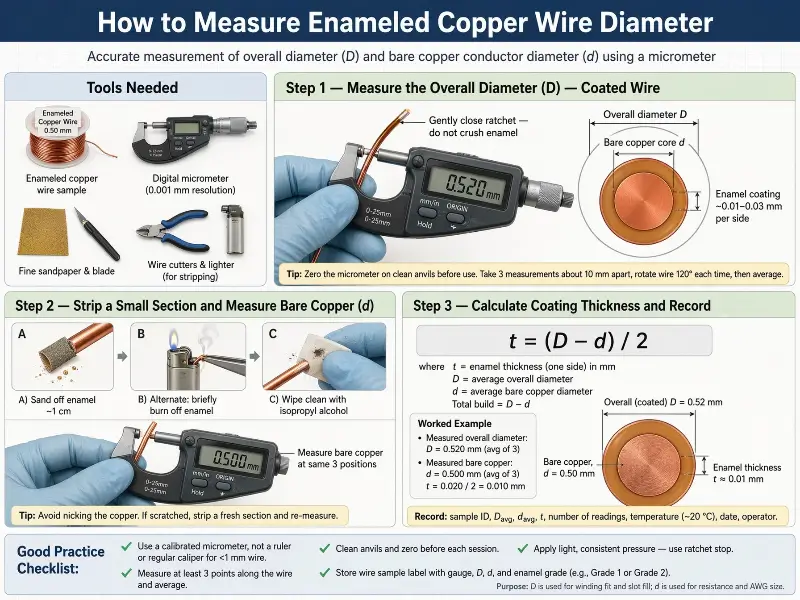
Diameter Parameter System: Conductor diameter, outer diameter, enamel coating increment, and out-of-roundness
The “diameter” of enameled wire is not a single value. A complete enameled copper wire involves at least four dimensional parameters, each clearly defined in the standard: Bare copper conductor diameter D.
The diameter of the pure copper conductor after removing the enamel coating. IEC 60317 calls it “conductor diameter,” which determines the conductor’s DC resistance, current carrying capacity, and mechanical strength.
This parameter, specified in IEC 60317-0-1, defines the conductor diameter range as 0.018–5.000 mm, using the R20 preferred number series, with R40 intermediate values inserted if necessary. Maximum Overall Outer Diameter OD.
The complete outer diameter after the enamel coating has cured, including the conductor and the enamel coating layer. IEC 60317 refers to this as the “overall diameter,” which is the actual occupied size in the winding winding design, determining the slot fill factor and insulation distance. Enamel Coating Increment.
Defined as OD − D (Note: In IEC 60317, increase refers to the difference between the outer diameter and the conductor diameter, i.e., twice the thickness of the enamel coating on one side; the industry commonly refers to “enamel coating thickness” as the thickness on one side t = increase/2).
This parameter specifies the minimum value according to Grade 1/2/3.
Grade 1 enamel coating is the thinnest and is used in precision instruments and high-frequency coils; Grade 3 enamel coating is the thickest and is used in general-purpose motors and transformers. Out-of-roundness f.
The difference between the maximum and minimum readings at the same cross-section. Ideally, enameled wire is perfectly round, f = 0; due to fluctuations in the coating process and wire drawing process, actual product f is usually controlled within the range of 0.005–0.010 mm.
The IEC standard does not set a hard upper limit for out-of-roundness; industry practice uses it as an auxiliary judgment indicator. Conductor deviation △D.
The difference between the measured conductor diameter and the nominal conductor diameter. A positive △D indicates a thicker conductor, and a negative △D indicates a thinner conductor.
The absolute value of the deviation must fall within the allowable range of the IEC 60317 tolerance table.
Understanding the definitions and interrelationships of these five parameters is the foundation for subsequent measurement method selection and tolerance judgment.
Selecting Measurement Methods by Conductor Diameter
Enameled wire conductor diameters cover 0.018–5.000 mm, spanning nearly three orders of magnitude.
The physical properties and measurement applicability vary significantly across different wire diameters. IEC 60851-2 and IEC 60317-0-1 specify different combinations of measurement methods based on diameter ranges: < 0.063 mm (AWG 42 and above, ultra-fine wire).
The measuring force applied by mechanical contact measuring tools is sufficient to flatten the copper conductor, resulting in a systematic underestimation of the diameter reading by 5%–10%.
Clause 4.1 of IEC 60317-0-1 explicitly stipulates that only the resistance method should be used for this wire diameter range: the conductor cross-sectional area is inferred by measuring the resistance per unit length, and then the equivalent diameter is calculated; direct measurement of the conductor diameter is not required. 0.063–0.200 mm (fine wire).
Dual verification using both the resistance method and the diameter method.
Micrometers can be used, but the measuring force must be strictly controlled according to IEC 60851-2 (P = 0.16–0.32 N/mm when 0.100 < d ≤ 0.45 mm).
Laser scanning diameter gauges are a better choice, offering accuracy of ±0.3 μm and being non-contact to avoid flattening. 0.200–0.500 mm (medium wire diameter, mainstream industrial range).
Both micrometers and laser scanning diameter gauges are suitable.
According to IEC 60851-2 Clause 4.1, the number of measurement points is 6 points (3 equal divisions circumferentially × 2 sample positions). 0.500–1.000 mm (relatively heavy duty wire diameter). A single measurement point with a micrometer meets the accuracy requirements; laser scanning or laser diffractometers are used for online quality control and high-precision laboratory scenarios. > 1.000 mm (heavy duty wire diameter). A micrometer is sufficient for a single measurement point.
Accuracy 0.001–0.002 mm, measuring range 0–25 mm or 0–50 mm.
Advantages include low cost, high portability, and no power supply required; disadvantages include the risk of flattening due to contact measurement, human error caused by parallax, slow single measurement speed, and unsuitability for online inspection. Digital micrometer.
Mechanical structure plus electronic reading module, accuracy 0.001 mm, can output data to PC or PLC for SPC analysis.
The cost is 30%–50% higher than that of purely mechanical measuring devices, but the advantages are data traceability and unambiguous readings. IEC 60851-2 Clause 4.2 explicitly encourages the use of digital measuring devices when conditions permit.
Laser Scanning Diameter Gauge. Non-contact measurement; a laser beam is emitted and scans the object being measured, and the receiver calculates the diameter based on the shadow length.
Accuracy can reach ±0.3 μm (using SCreate’s similar products as an example), with a measurement frequency of thousands of times per second.
Advantages include 100% online detection, no damage to enamel coating, and automatic feedback control via PLC linkage; limitations include the object being measured must pass perpendicularly through the measuring beam, and larger measurement errors for curved or twisted sections. Laser Diffraction Diameter Gauge.
Based on the principle that laser diffraction patterns change with diameter.
Table 1: Reference Data
| Conductor Diameter Range | Recommended Measurement Method | Main Tools | Precautions |
|---|---|---|---|
| < 0.063 mm | Resistance Method Only | DC Resistance Bridge | Contact method may flatten the sample |
| 0.063–0.200 mm | Resistance Method + Diameter Method | Digital Micrometer + Resistance Bridge | Dual Verification; Measurement Force Control |
| 0.200–0.500 mm | Diameter Method Mainly | Micrometer/Laser Scanning | 3 Circumferential Points × 2 Positions |
| 0.500–1.000 mm | Diameter Method | Micrometer/Laser Scanning/Laser Diffraction | Equipment Resolution ≤ 2 μm |
| > 1.000 mm | Diameter Method | Micrometer/Laser Scanning | Single Measurement Point Sufficient |
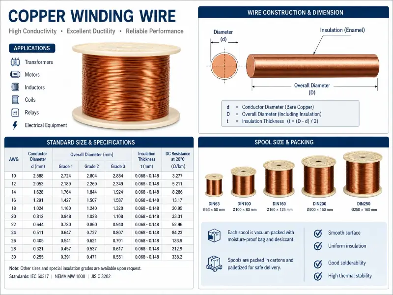
Measurement Tools: Comparison of Mechanical, Laser, and Optical Solutions
Accuracy ±0.12 μm, repeatability ±0.06 μm.
Advantages include 2.5 times higher accuracy than scanning gauges; limitations include high equipment cost, and currently fewer than 3 manufacturers worldwide can mass-produce such equipment. Optical Microscope and Pneumatic Gauge.
Used for measuring ultra-fine wires (< 0.1 mm).
The pneumatic gauge infers dimensions based on airflow changes, with an accuracy of ±0.001 mm, and is non-contact; the optical microscope is used for visual inspection (enameled coating bubbles, scratches) and 6–10x magnification. | Tools | Accuracy | Applications | Contact/Non-contact | Typical Uses | |—|—|—|—|—| | Mechanical Outside Micrometer | 0.001–0.002 mm | All round wire | Contact | Incoming material sampling | | Digital Micrometer | 0.001 mm | All round wire | Contact | Laboratory/QC | | Laser Scanning Diameter Gauge | ±0.3 μm | ≥ 0.05 mm | Non-contact | Online production line | | Laser Diffraction Diameter Gauge | ±0.12 μm | ≥ 0.02 mm | Non-contact | High-precision laboratory | | Optical Microscope/Pneumatic Measuring Instrument | ±0.001 mm | < 0.1 mm | Non-contact | Ultra-fine wire measurement | Table 2: The core principle for selecting wire diameter measuring tools is that the tool’s accuracy must match the wire diameter.
For example, when using a laser diffractometer for 0.020 mm ultra-fine wire, the irregularity of the wire itself leads to a deterioration in the signal-to-noise ratio of the diffraction pattern, resulting in lower measurement accuracy than the resistance method.
Higher accuracy is not always better; selection must be based on wire diameter and application scenario.
Cut a sample at least 1 m long from the finished spool, discarding the 100 mm end to avoid shear deformation.
The sample must be free of mechanical defects such as sharp bends, knots, and flattening. Step 2: Environmental Conditioning.
According to IEC 60851-1 Chapter 4, the test environment temperature should be controlled between 15–35 °C and the relative humidity between 45%–75%.
The sample should be pre-conditioned in the test environment for at least 4 hours to allow the enamel coating to reach moisture equilibrium. Step 3: Instrument Calibration.
Mechanical micrometers should be zero-calibrated using standard gauge blocks or ring gauges; laser diameter gauges should be calibrated using standard diameter bars; calibration records should be kept for at least 3 years. Step 4: Overall Outer Diameter Measurement.
With the enamel coating intact, select measurement points according to the following rules: – Conductor diameter ≤ 0.200 mm: Measure once every 1 m, for a total of 3 times, and take the average value. – Conductor diameter > 0.200 mm: Measure 3 times at each sample location divided into 3 equal parts circumferentially, and take the average value of 6 measurements from 2 sample locations.
The anvil diameter is measured according to IEC 60851-2: 2–8 mm for round wire < 0.1 mm, and 5–8 mm for 0.1–1.0 mm.
The measuring force is controlled within the range of P (N/mm): P = 0.16–0.32 N/mm when 0.100 < d ≤ 0.45 mm. Step 5: Enamel Removal and Conductor Diameter Measurement.
The enamel coating removal method is selected according to the wire diameter: – Mechanical scraping: Scraping off the enamel coating with a blade or sandpaper, suitable for heavy duty wires ≥ 0.500 mm, fast operation but easily damages the copper conductor surface. – Chemical solvents: Immersing in acetone, dichloromethane, or a special enamel remover to dissolve the enamel coating, suitable for medium wire diameters of 0.100–0.500 mm, without damaging the copper conductor. – Burning method: Rapidly burning the enamel coating with an alcohol lamp, suitable for rapid laboratory verification, requires high operator experience, and prolonged burning may cause copper wire oxidation.
Table 2: Reference Data
| Tools | Accuracy | Applications | Contact/Non-contact | Typical Uses |
|---|---|---|---|---|
| Mechanical Outside Micrometer | 0.001–0.002 mm | All round wire | Contact | Incoming material sampling |
| Digital Micrometer | 0.001 mm | All round wire | Contact | Laboratory/QC |
| Laser Scanning Diameter Gauge | ±0.3 μm | ≥ 0.05 mm | Non-contact | Online production line |
| Laser Diffraction Diameter Gauge | ±0.12 μm | ≥ 0.02 mm | Non-contact | High-precision laboratory |
| Optical Microscope/Pneumatic Measuring Instrument | ±0.001 mm | < 0.1 mm | Non-contact | Ultra-fine wire measurement |
IEC 60851-2 Standard Measurement Procedure
After enamel removal, measure the conductor diameter according to the same rules as in step 4. Step 6: Parameter calculation: – enamel coating increment = OD − D – enamel coating thickness t = (OD − D) / 2 – Out-of-roundness f = Maximum reading of the same cross section − Minimum reading – Conductor deviation △D = Measured conductor diameter − Nominal conductor diameter Step 7: Acceptance judgment.
Refer to the IEC 60317 tolerance table to find the allowable ranges for the conductor diameter, overall outer diameter, and enamel coating increment.
Exceeding any of these limits results in a non-compliance. IEC 60851-2 Clause 4.1 imposes strict requirements on equipment resolution: instruments measuring ≤ 0.200 mm wires must have a resolution ≤ 1 μm; instruments measuring > 0.200 mm wires must have a resolution ≤ 2 μm.
Micrometers with resolutions lower than this are not permitted for fine wire measurements.
The IEC standard does not set a hard upper limit for out-of-roundness.
Industry practice considers f < 0.005 mm as excellent, 0.005–0.010 mm acceptable, and > 0.010 mm requires attention to the painting process. enamel coating thickness t: t = (OD − D) / 2 Example: Outer diameter 0.566 mm, conductor diameter 0.500 mm, t = (0.566 − 0.500) / 2 = 0.033 mm. IEC 60317 Grade 2 requires a minimum increment of ≥ 0.045 mm for the enamel coating.
This increment is defined as increase = OD − D = 0.066 mm; calculated on a single side of the enamel coating thickness, t = 0.033 mm.
These two values are consistent.
In this example, t = 0.033 mm < 0.045 mm, which is considered non-compliant.
Complete calculation case (IEC 60317 Grade 2, 0.500 mm nominal conductor) Measured data: Overall outer diameter OD = 0.566 mm (standard requirement ≤ 0.566 mm, acceptable); Conductor diameter D = 0.504 mm (standard requirement 0.495–0.505 mm, acceptable); Conductor deviation ΔD = +0.004 mm (tolerance ±0.005 mm, acceptable); Out-of-roundness f = 0.004 mm (industry convention < 0.010 mm, acceptable); enamel coating thickness t = 0.033 mm (Grade 2 lower limit ≥ 0.045 mm, unacceptable).
The engineering significance of this case is that although the outer diameter and conductor diameter both meet the tolerances, the enamel coating thickness is lower than the Grade 2 lower limit.
In actual production, it is common to only measure OD and D while ignoring the calculation of enamel coating thickness, which is one of the main technical reasons for pressure breakdown and customer complaints.
Eight typical error sources—contact flattening, bending deformation, paint peeling damage, temperature drift, parallax/reading error, gauge calibration drift, insufficient representativeness of measuring points, and the influence of environmental humidity—are analyzed one by one:
Contact Flattening.
The measuring force of a mechanical micrometer is concentrated at the contact point of the anvil, creating localized compressive stress on the copper wire.
The thinner the wire, the more significant the flattening effect. A 0.100 mm enameled wire measured with a standard micrometer (measuring force approximately 5 N) may have a reading as low as 0.092 mm, a relative deviation of -8%.
The solution is to use laser diameter measurement (non-contact), or strictly control the measuring force to 0.16–0.32 N/mm according to IEC 60851-2. Bending Deformation.
Unstretched samples are “straightened” between micrometers, causing an overestimation of the diameter or distortion of the roundness of the same cross-section.
The solution is to gently pull the sample on a flat surface before measurement (avoiding tensile deformation), and allow the sample to rest naturally during measurement. Paint Removal Damage.
Prolonged burning during the firing process causes oxidation and discoloration of the copper wire surface, resulting in an overestimation of the diameter; excessive mechanical scraping creates grooves on the copper wire surface, leading to an underestimation of the diameter.
The solution is to prioritize the use of chemical solvents (immersion in acetone for 30 minutes), which causes zero damage to the copper wire. Temperature Drift.
The coefficient of linear expansion of copper is approximately 17 × 10⁻⁶ /°C.
When measuring a 1.000 mm wire in a 30 °C environment (standard temperature 20 °C), the diameter deviation is approximately 0.0002 mm.
Calculation of Conductor Deviation, Out-of-Roundness, and enamel Coating Increment
While the individual value may seem small, the cumulative tolerance judgment can lead to misjudgment.
The solution is to measure in a constant temperature laboratory at 20 ± 1 °C or correct using a formula. Parallelism and Reading Error.
Mechanical micrometer readings rely on the operator’s interpretation of the main scale and micrometer thimble, which is prone to human error on the order of ±0.001 mm.
The solution is to use a digital micrometer with a direct LCD display, or to take three readings per sample and average them. Grip Calibration Drift.
Micrometers drift to zero after a period of use; the environmental compensation parameters of laser diameter gauges may fail.
The solution is to calibrate monthly using standard gauge blocks and archive the calibration records for future reference. Insufficient Representativeness of Measurement Points. A single measuring point cannot reflect the uniformity of the entire 1 m sample length.
The solution is to use at least 3 measuring points (for thin wire) or 6 measuring points (for heavy duty wire) according to IEC 60851-2. Ambient humidity influence.
Enameled wire expands in volume after absorbing moisture, resulting in a larger measured outer diameter.
Polyurethane enamel coating (UEW) exhibits particularly significant moisture absorption.
The solution is to control the test environment RH between 45% and 75%, and to pre-condition the sample for ≥ 4 hours.
Common Measurement Error Sources and Control Methods
There are two mainstream standards for enameled wire tolerance systems: IEC 60317 (European and Asian mainstream) and NEMA MW 1000 (North American mainstream).
The two systems differ significantly in their classification methods, parameter definitions, and tolerance ranges: IEC 60317 classification system.
The enamel coating is classified into three grades from thinnest to thickest: Grade 1, Grade 2, and Grade 3.
Grade 1 has the thinnest enamel coating and is used for precision instruments, sensors, and high-frequency coils.
Grade 2 is a general-purpose grade, covering most motor and transformer applications.
Grade 3 has the thickest enamel coating and is used for general-purpose motors, high-voltage transformers, and applications requiring high insulation strength. NEMA MW 1000 Build System.
The enamel coating is also classified into four grades from thinnest to thickest: Single Build, Heavy Build, Triple Build, and Quadruple Build.
Single Build corresponds to IEC Grade 1; Heavy Build corresponds to IEC Grade 2; Triple Build corresponds to IEC Grade 3; Quadruple Build has no corresponding IEC grade.
Exceeding any of these tolerances results in the entire wire being deemed unacceptable. Key Differences Between the Two Standards.
Taking a 0.500 mm nominal conductor as an example: NEMA MW 1000 Single Build has a maximum outer diameter of 0.513 mm, Heavy Build 0.529 mm, and Triple Build 0.544 mm; IEC 60317 Grade 2 has a maximum outer diameter of 0.566 mm.
The 0.529 mm tolerance of Heavy Build differs significantly from the 0.566 mm tolerance of IEC Grade 2.
Comparison of IEC 60317 and NEMA MW 1000 Tolerance Systems
The finished wires from these two standards are not directly interchangeable in terms of winding compatibility and insulation distance. Tolerance Trends: – The larger the conductor diameter, the larger the absolute tolerance value (0.100 mm ±0.003 mm, 2.000 mm ±0.020 mm) – this is an objective law of wire drawing process capability. – The relative tolerance value (tolerance/nominal) remains within the range of ±1%–3%. – The larger the Grade number, the looser the tolerance – Grade 1 is used for precision instruments, and Grade 3 is used for general-purpose motors. A common ambiguity in engineering practice: the purchase contract stipulates “according to IEC 60317 standard” but does not specify the Grade.
The industry practice is to default to Grade 2 – the strict tolerance of Grade 1 leads to high costs and long lead times, while the loose tolerance of Grade 3 may not meet the slot fill factor requirements for motor windings.
The overall outer diameter (3 measuring points), conductor diameter (3 measuring points), and enameled coating increment (calculated) are measured for each reel.
Results are compared against the purchasing specifications; batches exceeding tolerances are returned.
It is recommended to retain samples for at least 6 months for quality traceability and dispute resolution. In-Process Quality Control (IPQC).
The wire drawing and coating processes on the production line are sampled every 2 hours. A laser scanning diameter gauge monitors the overall outer diameter in real time; out-of-tolerance measurements trigger an automatic alarm and feedback to the take-up tension controller for process compensation. A process capability index (Cpk) ≥ 1.33 is the basic requirement; Cpk < 1.0 indicates a serious deficiency in process capability, requiring line shutdown for rectification. Finished Product Inspection (OQC).
Finished spools undergo 100% online inspection (laser diameter measurement) + 5% random sampling (digital micrometer + resistance method).
Sampling samples must complete a full set of tests for pressure resistance, elongation, and springback angle.
When the mean outer diameter drifts in the same direction for seven consecutive points, even if all data points are still within tolerance, a process review must be triggered—this mechanism can identify systematic deviations in advance and avoid the generation of batches of non-conforming products.
Classified by wire diameter range: < 0.063 mm (ultra-fine wire) is only suitable for resistance measurement; mechanical contact will cause the sample to flatten.
Table 3: Reference Data
| Nominal Conductor Diameter (mm) | Conductor Tolerance ± (mm) | Minimum Increment of G2 enamel coating (mm) | Maximum Outer Diameter of G2 (mm) |
|---|---|---|---|
| 0.100 | 0.003 | 0.016 | 0.125 |
| 0.315 | 0.004 | 0.035 | 0.367 |
| 0.500 | 0.005 | 0.045 | 0.566 |
| 0.710 | 0.007 | 0.053 | 0.789 |
| 1.000 | 0.010 | 0.063 | 1.094 |
| 1.500 | 0.015 | 0.071 | 1.606 |
| 2.000 | 0.020 | 0.075 | 2.112 |
Implementation of Diameter Measurement Quality Control
For 0.063–0.200 mm fine wire, dual verification using both resistance and diameter methods is recommended; the measuring force must be strictly controlled according to IEC 60851-2. > 0.200 mm (heavy duty wire) can be measured using a micrometer or laser scanning; the equipment resolution must meet the mandatory requirement of IEC 60851-2 ≤ 2 μm.
Classified by application scenario: For laboratory verification, a digital micrometer combined with the resistance method is recommended, with traceable output data.
For production line online monitoring, only laser diameter measurement is suitable; mechanical contact during online operation will damage the enamel coating and cannot achieve 100% inspection.
For incoming QC, 5%–10% can be sampled using a micrometer; the measurement process must comply with IEC 60851-2, and the judgment criteria must clearly correspond to IEC 60317 or NEMA MW 1000 Build system.
Table 4: Reference Data
| Nonconformity | Process Cause | Corrective Measures |
|---|---|---|
| Conductor Too Thin | Wear on Drawing Die/Uneven Annealing | Replace Drawing Die/Check Annealing Oven Temperature |
| Conductor Too Thick | Improper Drawing Die Matching | Re-match Die/Measurement Feedback |
| enamel coating Too Thin | Low Paint Concentration/Excessive Coating Speed | Adjust Paint Viscosity/Reduce Linear Speed |
| enamel coating Too Thick | High Paint Concentration/Excessive Coating Speed | Adjust Paint Viscosity/Increase Linear Speed |
| Out-of-roundness Exceeds Standard | Uneven Curing of enamel coating/Insufficient Coating Coats | Increase Coating Coats/Check Curing Oven |
| Out-of-tolerance Outer Diameter | Fluctuation in Increment of enamel coating | Paint Circulation Filtration/Optimize Coating Coats |
Selection of Diameter Measurement Schemes Based on Measurement Accuracy and Scenario
Only by comprehensively judging from three dimensions (accuracy, wire diameter, and scenario) can the optimal engineering solution be obtained between measurement accuracy, equipment investment, and operational efficiency.