


1 Introduction
Fiberglass Covered Wire is a multi-layered composite insulated wire with a core of round copper or round aluminum conductor, an outer layer of electrically-grade continuous-filament glass yarn braided or wrapped, and cured with insulating varnish. Its typical structure is: conductor – enamel coating (optional) – glass fiber covering layer – varnish finish.
According to ANSI/NEMA MW 1000-2018 Part 2 MW 41-C, FGCW is suitable for continuous operation in thermal class 155 (Class F) and corresponds to the IEC 60317-48 international standard. In demanding operating conditions such as high-voltage motors, traction motors, wind turbines, and frequency converters, FGCW has gradually become a key insulation solution for winding design.
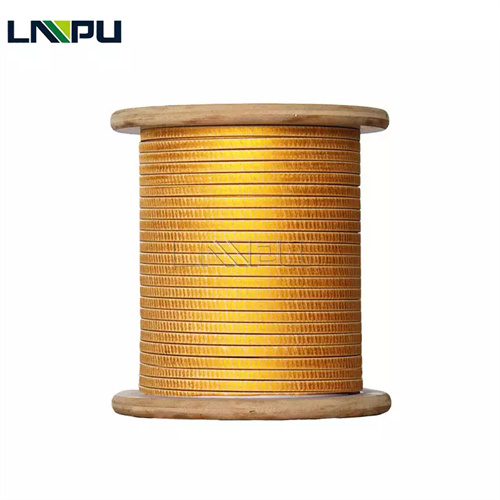
2 Material Structure and Insulation System
The insulation system of fiberglass covered wire (FGCW) consists of the following three layers, and the functions of each layer and their synergistic relationship are as follows:
- **Conductor**: Round copper (T2 / TU1) or round aluminum (1350 / 1370) as the current carrier; 2. **Enamelling Film** (optional): Provides basic electrical insulation, typically polyester imide (PEI), polyamide imide (PAI), etc., with an enamel coating grade of not less than 130; 3. **Glass Fiber Covering**: Electrical grade E-Glass continuous filament glass yarn is tightly, uniformly, and continuously woven or wound around the conductor or enamel coating; 4. **Varnish Finish**: After being treated with insulating varnish and cured, it forms a tough, dense, and moisture-resistant hard surface layer.
According to NEMA MW 41-C Clauses 3.3.8 and 3.3.2, the cladding layer should meet the following requirements: after bending the mandrel from 1d to 15d, the cladding layer should not crack to expose the underlying bare wire or enamel coating. This clause directly verifies the mechanical reliability of FGCW in winding manufacturing processes such as winding, shaping, and binding.
3 The motor adopts FGCW’s core technology advantages
3.1 thermal class and thermal lifetime
Glass fiber is an inorganic non-metallic material with a softening point of approximately 846 °C and a melting point above approximately 1000 °C. After treatment with a suitable impregnation system, typical FGCW (fiberglass reinforced plastic) thermal class is as follows:
| Thermal Rating | Temperature Index | Applicable Standards | Typical Impregnation Systems | —— | ———- | ———- | ————– | F | 155 °C | NEMA MW 41-C / IEC 60317-48 | polyester, polyesterimide | H | 180 °C | Double-layer glass fiber wrapping, glass fiber + polyimide composite | polyesterimide, polyimide | C | 220 °C and above | Special Impregnation Systems | Silicone, polyimide |
|---|
According to Montsinger’s rule of thumb, for every 10 K decrease in motor winding temperature, insulation life approximately doubles. FGCW offers a higher thermal margin than conventional polyester enameled round wire (thermal rating 155), which has direct engineering value in extending motor service life.
3.2 Dielectric Strength
NEMA MW 41-C Section 3.8.4 specifies the minimum dielectric breakdown voltage for FGCW (taking 4/0-9.5 AWG as an example):
- Single layer coverage: ≥ 170 V – Double layer coverage: ≥ 315 V – For those with an enamel coating, the breakdown voltage corresponding to that enamel coating should be added.
For 6 kV and above high-voltage motors, as well as motor stator windings driven by PWM frequency converters and subjected to high du/dt impulse voltages, the multilayer dielectric structure of FGCW can effectively suppress partial discharge (PD) and improve the safety margin of the insulation system.
3.3 Mechanical Strength
The motor windings are subjected to combined mechanical stresses during manufacturing and operation, including:
- Bending and tensile stress during the winding and shaping process; – Friction and compressive stress during end binding; – Electromagnetic vibration (twice the power supply frequency) and mechanical vibration during operation.
The glass fiber braided layer imparts high radial stiffness and wear resistance to the conductor surface, which can significantly reduce the engineering risk of damage to the enamel coating during manufacturing.
3.4 Chemical stability and moisture resistance
Glass fiber exhibits excellent chemical inertness, tolerating weak acids, weak alkalis, mineral oils, and most organic solvents. When combined with a cured impregnating varnish layer, the entire insulation system demonstrates significantly better resistance to moisture, oil mist, dust, and cooling media than a single organic enamel coating. This property makes FGCW suitable for corrosive or humid environments such as oil-immersed transformers, oil-cooled motors, offshore wind power, chemical plants, and mines.
3.5 Thermal Shock Resistance and Overload Capacity
According to IEC 60034-1, motor windings will experience short-term temperature rises during startup, stall, and transient overload conditions. FGCW, through its glass fiber skeleton, disperses thermal stress, and its coefficient of linear expansion is significantly lower than that of a pure enamel coating system, effectively suppressing insulation cracking and blistering under thermal cycling.
4 Typical Application Scenarios
The table below lists application recommendations for FGCW in major motor types:
| Motor Type | Recommended Structure | Engineering Basis | ———- | ———- | ———- | High Voltage Motor (≥ 6 kV) | Double-layer glass fiber wrapped enameled wire | Improved dielectric strength and anti-corona performance | Traction motor, hoisting and metallurgical motor | Glass fiber wrapped + H-class impregnation | Vibration resistant, locked rotor overload resistant | Wind turbine generator, water pump motor | Glass fiber paper wrapped or glass fiber enameled | Moisture resistant, thermal cycling resistant | Oil-immersed transformer winding | Glass fiber enameled rectangular wire | Mineral oil resistant, long-term thermal stability | Variable frequency drive motor | Double-layer glass fiber wrapped round/flat wire | High-frequency impulse voltage (du/dt) resistant | Mining/Marine/Explosion-proof motor | Glass fiber + special impregnation | Corrosion resistant, mechanical shock resistant |
|---|
When the motor is designed to operate at temperatures exceeding Class F (155 °C), or when it is subjected to single or combined severe operating conditions such as vibration, oil mist, humidity, high voltage, or frequent overload, FGCW has irreplaceable engineering advantages over conventional enameled wire.
5 Key Parameters for Selection
During the design and procurement phases, the selection and evaluation of FGCWs should be carried out from multiple dimensions, including conductor materials, geometric specifications, insulation structure, and standard compliance. For conductor materials, copper (T2/TU1) is superior due to its high conductivity and low contact resistance, making it suitable for high power density and pulsed load conditions; aluminum (1350/1370), with its lightweight and cost advantages, is suitable for large-size windings and weight-sensitive equipment. Regarding geometric specifications, round wires typically cover the AWG 4/0–30 range, while flat wires generally have a thickness between 0.8–10 mm and a width between 2–25 mm, depending on slot fill factor and current density requirements. For insulation structure, the number of layers (single/double) directly relates to dielectric strength but also affects conductor outer diameter and wiring manufacturability; whether to install a film-insulated underlayer (enamel coating) requires a comprehensive evaluation considering design margins and manufacturing costs. The choice of impregnation varnish system directly determines the thermal rating. Polyester and polyimide correspond to Class F, polyimide covers Class H and above, and silicone is suitable for Class C high-temperature environments. Furthermore, suppliers should be able to provide type test reports conforming to standards such as ANSI/NEMA MW 1000, IEC 60317 series, GB/T 7672, and JIS C3202, and possess UL, REACH, RoHS, and ISO 9001/14001/45001 system certifications to ensure dual compliance of design inputs and market access.
6 Frequently Asked Questions
Q1: Can FGCW completely replace enameled round wire?
It cannot be easily replaced. The engineering advantages of FGCW are concentrated in high temperature, high mechanical stress, and high dielectric strength conditions; for consumer electronics and low-voltage, low-power motors, enameled round wire still has a cost advantage.
Q2: Is a higher FGCW thermal class always better?
No. Increasing the thermal class will lead to higher costs and increased process complexity. The appropriate thermal class should be selected based on the actual operating temperature and design life of the motor.
Q3: Is double-layer coverage always better than single-layer coverage?
Double-layer covering offers higher dielectric strength, but the increased outer diameter will affect the slot fill factor, requiring an engineering trade-off between insulation margin and slot utilization.
Q4: Is FGCW applicable to variable frequency drive motors?
This is applicable and recommended. The PWM inverter output has a high du/dt impulse component, and the multilayer dielectric structure of the FGCW has a significant effect on suppressing partial discharge.
Q5: What indicators should be considered when evaluating the quality of FGCW?
We recommend paying attention to: ① Whether there is a type test report under the NEMA MW 1000 or IEC 60317 system; ② The explicitness of the impregnation varnish grade and curing process; ③ The stability and distribution characteristics of batch breakdown voltage data.
7 Conclusion
The application of FGCW in motor windings is essentially an engineering choice for “upgrading the insulation system under operating conditions.” When operating parameters such as temperature, vibration, voltage, and overload approach the limits of conventional wire, FGCW provides not only an improvement in heat resistance and temperature rise, but also an engineering leap in the safety margin of the entire insulation system. Proper selection of FGCW can extend the design life of a motor from 5-10 years under normal operating conditions to 15-20 years.
Contact Information:
- E-mail: office@cnlpzz.com
- WhatsApp: 0086-19337889070
- Zhengzhou LP Industry Co., Ltd.