


1 Introduction
Flat enameled copper wire, also known as rectangular magnet wire or strip wire, and round enameled copper wire are the two fundamental categories in the winding wire industry. Round enameled copper wire uses a circular cross-section copper conductor as the base material and is coated with an insulating layer; it is the most widely used conductor form in motor, transformer, and inductor windings. Flat enameled copper wire uses a rectangular or square cross-section copper conductor as the base material and is coated with an insulating layer; it has irreplaceable advantages over round wire in applications such as large-size windings, high-frequency windings, and high-current windings.
Deciding when to use flat enameled copper wire to replace round wire is a critical technical decision for winding engineers, transformer and motor designers. This article, based on standards such as NEMA MW 1000-2018, IEC 60317 series, and IEC 60034, systematically explains the engineering basis and decision-making logic for replacing round wire with flat enameled copper wire from five dimensions: material composition, performance differences, slot fill factor analysis, application scenarios, and selection decisions.
2 Comparison of Material Composition
2.1 Composition of Round Enameled Copper Wire
Round enameled copper wire consists of a round cross-section copper conductor and an enamel coating. The copper conductor, according to NEMA MW 1000-2018 standard, commonly uses grades T2 (C11000) ordinary electrolytic copper with a copper content of not less than 99.90% and TU1 (C10100) oxygen-free copper with a copper content of not less than 99.97%. The enamel coating system covers multiple thermal grades including polyurethane, polyester, polyester imide, and polyamide imide, with common specifications ranging from 0.05 to 6.00 mm in diameter.
The manufacturing process for round enameled copper wire is mature, including continuous casting and rolling, stretching, annealing, enameling, and curing. The enameling thickness is divided into three grades: Grade 1, Grade 2, and Grade 3, corresponding to different dielectric strength and winding fill factor requirements.
2.2 Composition of Flat Enameled Copper Wire
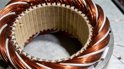
Flat enameled copper wire consists of a rectangular or square cross-section copper conductor and an enamel coating. The copper conductor is made of the same material as the round wire, with common cross-sections being rectangular wire with a width of 2.00 to 16.00 mm and a thickness of 0.80 to 5.60 mm, and square wire with a side length of 1.00 to 8.00 mm. The enamel coating system is compatible with the round wire and covers the NEMA MW 18/20/26/27/28/30/36 series.
The manufacturing process of flat enameled copper wire differs from that of round wire, requiring specialized steps such as rectangular rolling, stretching, annealing, enameling coating, and curing. The rectangular cross-section demands high precision control, with a width-to-thickness ratio typically not exceeding 8:1 to prevent uneven enameling coating and winding deformation. According to NEMA MW 1000-2018 standard, specific regulations exist for the corner radius, enameling coating thickness, and insulation strength of rectangular enameled wire.
2.3 Core Differences
Round wire and flat wire differ systematically in cross-sectional shape, winding method, performance parameters, and application scenarios. Round wire is suitable for small-size, densely wound applications with high requirements for enamel coating integrity; flat wire is suitable for large-size applications with high slot fill factor requirements and optimized winding heat dissipation.
3 Performance Difference Comparison
3.1 Slot Fill Rate Difference
Slot fill factor is the proportion of slot space occupied by the winding wire, and it is a core indicator for measuring the compactness of winding design. For round wires, due to their circular cross-section, there are unavoidable gaps between adjacent conductors, resulting in an upper limit of approximately 50% to 70% slot fill factor. For flat wires, due to their rectangular cross-section, adjacent conductors can fit tightly together, allowing for an upper limit of 80% to 90% slot fill factor.
Increased slot fill factor directly translates to improved winding space utilization. With the same slot space, flat wire can accommodate more copper cross-sectional area, increasing the winding’s current carrying capacity and power density. Under the same power design target, flat wire can reduce winding slot size, lowering the overall size and weight of the motor or transformer.
3.2 Skin Effect and AC Resistance
Round wires are significantly affected by the skin effect under high-frequency AC conditions. The skin depth is inversely proportional to the square root of the frequency; the higher the frequency, the smaller the skin depth, and the current concentrates on the conductor surface. While the current distribution in the circumferential direction of a round wire is uniform, the current density in the central region is low, resulting in insufficient material utilization.
Flat wires are also affected by the skin effect at high frequencies, but due to their larger cross-sectional area and surface area, their heat dissipation performance is significantly better than that of round wires. The high-frequency AC resistance of flat wires is 10% to 30% lower than that of round wires of the same cross-sectional area, and their advantages are significant in mid-frequency and high-frequency scenarios above 1 kHz.
3.3 Heat Dissipation Performance
The heat dissipation of the round wires is mainly achieved through convection between the surface of the enamel coating and the air. The gaps between the round wires provide channels for the cooling medium, but the surface area to volume ratio of the conductors is relatively small.
Flat wires offer significantly better heat dissipation performance than round wires. The wide facets of a flat wire provide a large surface area, allowing heat to be rapidly conducted to the cooling medium. In oil-immersed transformers, the large contact area between the flat wire’s wide facets and the transformer oil significantly improves heat dissipation efficiency; in air-cooled motors, the heat exchange efficiency between the flat wire’s wide facets and the air is 30% to 50% higher than that of round wires.
3.4 Mechanical Strength
The mechanical strength of a round wire is uniformly distributed in all directions, exhibiting excellent bending resistance and capable of withstanding repeated bending of mandrel diameters from 1d to 5d without damage. The moment of inertia of the round wire’s cross-section is symmetrically distributed.
The mechanical strength of flat wire is directional. Its bending stiffness is higher along the longer side than along the shorter side, and the greater the width-to-thickness ratio, the more pronounced the directionality. Flat wire is prone to enamel coating cracking when bent along its longer side, requiring special processing to prevent this. Flat wire exhibits better bending resistance than round wire when bent along its shorter side.
3.5 Integrity of enamel coating
Because of its uniform and symmetrical cross-section, the round wire has a uniform and high-quality enamel coating. Under bending, tension, and torsion conditions, the enamel coating on the round wire is less prone to cracking.
Because of its rectangular cross-section, flat wire is more difficult to coat with enamel coating at its corners, resulting in significantly more uneven enamel coating thickness compared to round wire. The enamel coating thickness at the rounded corners of flat wire is approximately 60% to 80% of that in the planar areas, making these areas weak points in dielectric strength. When flat wire is bent, stress concentrates at the corners, increasing the risk of enamel coating cracking by 2 to 3 times compared to round wire.
3.6 Conductor Cross-sectional Area and Current Carrying Capacity
Under the same slot space and the same insulation class, the cross-sectional area of flat wire is increased by 25% to 50% compared to round wire, corresponding to a 25% to 50% increase in current carrying capacity. This relationship is the core reason why flat wire is preferred for high-current and high-power windings.
For the same cross-sectional area, the width of a flat wire is much greater than its thickness, and the unfolded length of the winding end is 10% to 20% longer than that of a round wire, resulting in increased copper usage at the end. The design and manufacturing process of the winding end need to be adjusted accordingly.
4 Detailed Explanation of Application Scenarios
4.1 Large-scale power transformer
Large-scale power transformers are the most important application scenario for flat enameled copper wire. Flat enameled copper wire is commonly used in the windings of large-scale power transformers, rectifier transformers, and electric furnace transformers with voltage levels of 110 kV and above. Transformer windings require high slot fill factor, high heat dissipation efficiency, and low losses, and the advantages of flat wire perfectly match these requirements.
The flat wire used in transformer windings is typically 4.00 to 12.00 mm wide and 1.50 to 5.00 mm thick, with an enamel coating system of polyester imide or polyamide imide. In oil-immersed transformers, the large contact area between the wide surface of the flat wire and the transformer oil significantly improves heat dissipation efficiency, reducing winding temperature rise by 10 to 15 K compared to round wire.
4.2 Large Motor Windings
Flat enameled copper wire is another important application for large motor windings. The stator and rotor windings of large three-phase asynchronous motors, synchronous motors, and DC motors with a power output of 75 kW or more commonly use flat wire. Large motor windings require high power density, high slot fill factor, and high heat dissipation efficiency, making flat wire the preferred choice.
Flat wire windings for large motors typically range in width from 3.00 to 10.00 mm and thickness from 1.00 to 4.00 mm, with enamel coating systems covering multiple thermal grades such as B, F, and H. The high slot fill factor of flat wire windings increases motor power density by 15% to 25% compared to round wire windings.
4.3 High-Frequency Electronics transformer
High-frequency electronics applications utilize flat enameled copper wire in the electronics field. The windings of switching power supplies, induction heating transformers, and welding machine transformers commonly employ flat Litz wire or single-strand flat wire. The low AC resistance and excellent heat dissipation performance of flat wire at high frequencies are its core advantages in high-frequency applications.
Flat wires used in high-frequency electronic transformers typically have a width of 2.00 to 8.00 mm and a thickness of 0.50 to 2.00 mm, with an enamel coating system of polyurethane or polyester imide. The Litz wire structure offers significant advantages in high-frequency applications ranging from 10 kHz to 1 MHz.
4.4 traction motor and rail transit
Traction motors and rail transit windings are high-reliability applications using flat enameled copper wire. Flat wire is commonly used in the windings of electric vehicle drive motors, rail transit traction motors, and subway vehicle traction motors. The high power density, high slot fill factor, and excellent heat dissipation performance of flat wire are its core advantages in traction applications.
The application of flat wire windings in new energy vehicle drive motors has developed rapidly in recent years, and flat wire motors, also known as hairpin motors, have become the mainstream solution for 800-volt high-voltage platform drive motors. Flat wire motors offer 20% to 30% higher power density and 1% to 2% higher efficiency compared to round wire motors.
4.5 Large Reactors and Inductors
Large reactors and inductors are traditional applications of flat enameled copper wire. Flat wire is commonly used in the windings of power system reactors, filter reactors, and smoothing reactors. The high current carrying capacity, low loss, and excellent heat dissipation performance of flat wire are its core advantages in reactor applications.
Flat wires used in large reactors typically have a width of 4.00 to 16.00 mm and a thickness of 1.50 to 5.00 mm, with an enamel coating system of polyester imide or polyamide imide. The high cross-sectional area of flat wires offers significant advantages for reactors with fewer turns and higher current requirements.
4.6 Scenarios where flat wire is unsuitable
Flat wire is not suitable for all winding scenarios. Round wire should be preferred in the following scenarios:
Miniature windings: Miniature windings with a diameter of less than 1.00 mm, precision inductors, and sensor coils. Flat wire is difficult and costly to manufacture in small sizes; round wire should be used instead.
Densely wound windings: These are used in miniature transformers, high-frequency inductors, and headphone coils due to their high number of turns and compact size. Round wire offers superior flexibility in winding.
Complex-shaped windings: irregular-shaped windings, non-standard-shaped windings, and special windings with limited space. round wire is more adaptable to complex shapes.
Automated precision winding: Ultra-fine wire turns wound by a high-precision automated winding machine. The process maturity of round wire on automated winding machines is superior to that of flat wire.
Economically sensitive scenarios: Cost-sensitive home appliances and consumer electronics. Round wire prices are typically 20% to 50% lower than flat wire prices.
5 Selection Decision Matrix
5.1 Decision Factors
When to choose flat wire over round wire should be based on a comprehensive evaluation of the following decision factors:
Power density: For windings requiring high power density, flat wire should be preferred. The high slot fill factor of flat wire directly translates to high power density.
Slot space utilization: For windings with limited slot space and requiring maximum copper cross-sectional area, flat wire should be the preferred choice.
Heat dissipation requirements: For windings requiring high heat dissipation efficiency and low temperature rise, flat wire should be the preferred choice.
Frequency characteristics: For high-frequency applications, flat wire should be preferred, as its high-frequency AC resistance is lower than that of round wire.
Current carrying capacity: For windings requiring high current and high current carrying capacity, flat wire should be preferred.
Winding size: For large-size windings such as those used in large motors and large transformers, flat wire should be preferred.
Economic efficiency: For cost-sensitive scenarios, round wire should be the preferred choice.
Processability: For complex shapes and high-precision winding scenarios, round wire should be the preferred choice.
5.2 Decision Logic
The engineering decision to replace round wire with flat wire should follow the following logic:
The first step is to assess the power density requirements of the windings. If high power density is required and slot space is limited, flat wire should be the preferred choice.
The second step is to assess the operating frequency and heat dissipation requirements. For high-frequency applications or applications requiring high heat dissipation efficiency, flat wire should be the preferred choice.
The third step is to assess the current carrying capacity and winding size. For high current and large winding size, flat wire should be the preferred choice.
The fourth step is to assess the feasibility of the process. The winding process, insulation process, and terminal connection process of flat wire are different from those of round wire, so the process capability needs to be assessed.
The fifth step is to assess the cost budget. Flat wire is typically 20% to 50% more expensive than round wire, so cost sensitivity needs to be evaluated.
Step 6: Comprehensive decision-making. If the first four steps all favor flat wire and the cost is acceptable, then choose flat wire; otherwise, choose round wire.
5.3 Decision-Making Cases
Case 1: 110 kV large power transformer winding. High power density, limited slot space, high heat dissipation efficiency required, mature technology, and acceptable cost. Decision: Flat wire selected.
Case 2: 1.5 kW household air conditioner motor winding. Medium power density, relatively large slot space, moderate heat dissipation requirements, cost-sensitive, and mature technology. Decision: Use round wire.
Case 3: 800V New Energy Vehicle Drive Motor Winding. Extremely high power density, strictly limited slot space, high heat dissipation efficiency required, high-frequency PWM application, special process development needed, and acceptable cost. Decision: Select flat wire, i.e., the hairpin motor solution.
Case 4: Miniature Inductors for Consumer Electronics. Extremely small size, dense winding, complex shape, cost-sensitive. Decision: Use round wire.
Case 5: Industrial Control Relay Coil. Medium power, standardized design, cost-sensitive. Decision: Use round wire.
5.4 Process Support Requirements
The following process capabilities are required when selecting flat wire:
Flat wire winding process: Flat wire winding requires specialized winding equipment, and the winding parameters differ from those for round wire. Winding tension, winding speed, and winding temperature must be precisely controlled.
flat wire shaping process: After the flat wire winding is formed, it needs to be shaped to ensure the winding’s dimensional accuracy and mechanical strength.
flat wire insulation process: flat wire windings require insulation treatments such as end insulation, interlayer insulation, and overall impregnation. The process flow is different from that of round wire.
flat wire terminal connection process: flat wire terminal connection requires the use of special processes such as copper terminals, soldering, and laser welding. The terminal design is different from that of round wire.
flat wire test verification: flat wire windings need to undergo specific tests such as breakdown voltage, temperature rise, vibration, and impact verification. The test methods are slightly different from those for round wire.
6 Engineering Evolution Trends
Flat wire and round wire exhibit a complementary and coexisting development trend in the winding wire field. Round wire maintains a dominant position in applications such as small and medium-sized motors, home appliances, consumer electronics, and precision inductors. Flat wire continues to expand its application in applications such as large transformers, large motors, traction motors, and high-frequency electronic transformers.
In the field of new energy vehicle drive motors, flat wire motors, also known as hairpin motors, have become the mainstream solution for 800-volt high-voltage platforms. Flat wire motors offer significantly better power density, efficiency, and heat dissipation performance than round wire motors. The global market for flat wire motors in new energy vehicles is projected to maintain an annual growth rate of over 30% from 2026 to 2030.
In the field of rail transit traction motors, the application of flat wire windings in subway, high-speed rail, and intercity EMU traction motors continues to expand. High power density, high efficiency, and low temperature rise are core requirements for rail transit traction motors.
In the wind power sector, the application of flat wire windings in large wind turbines is gradually expanding. As the single-unit power output of large wind turbines continues to increase, the high power density and low loss of flat wire windings are core requirements for wind power applications.
In the field of high-voltage direct current (HVDC) transmission, the application of flat wire windings in converter transformers and smoothing reactors continues to expand. The high current, low loss, and excellent heat dissipation performance of flat wire windings are core requirements for HVDC applications.
In terms of new materials, flat wire enamel coating systems are evolving towards higher heat resistance, higher mechanical strength, and higher dielectric strength. The application of high-end enamel coatings such as polyamide-imide and polyimide in flat wires is gradually expanding. Composite enamel coating systems, such as flat enamel wire with glass fiber coating and flat enamel wire with mica tape coating, are maturing in the application of new insulation structures in large transformers and high-voltage windings.
In terms of new processes, automated flat wire winding, laser welding of flat wire terminals, and vacuum pressure impregnation of flat wire windings are gradually maturing. The production efficiency, product quality, and reliability of flat wire windings continue to improve.
7 Conclusion
Flat enameled copper wire and round enameled copper wire are the two basic categories in the winding wire field, each with its own advantages and application scenarios. When to choose flat wire instead of round wire should be based on a comprehensive evaluation of multiple dimensions such as power density, slot fill factor, heat dissipation requirements, frequency characteristics, current carrying capacity, winding size, economy, and manufacturability.
Flat wires offer irreplaceable advantages over round wires in large-size, high-power, high-frequency, and high-current applications such as large power transformers, large motors, high-frequency electronic transformers, traction motors, and large reactors. Round wires maintain a dominant position in applications such as small and medium-sized motors, home appliances, consumer electronics, precision inductors, and complex-shaped windings.
The engineering decision to replace round wire with flat wire should follow a scientific decision-making logic, comprehensively assessing technical requirements and economic costs, and matching the optimal conductor configuration to the winding design. With the development of strategic emerging industries such as new energy vehicles, rail transit, wind power, and high-voltage direct current transmission, flat enameled copper wire will complement and upgrade round wire in more scenarios, jointly supporting the continued development of power electronics, energy conversion, transportation, and other fields.
Contact information: E-mail office@cnlpzz.com, WhatsApp 0086-19337889070, Zhengzhou LP Industry Co., Ltd.
Contact Information:
- E-mail: office@cnlpzz.com
- WhatsApp: 0086-19337889070
- Zhengzhou LP Industry Co., Ltd.