

Introduction and Engineering Background
Fiberglass Insulated Electrical Wire (Glass-Fiber Covered Magnet Wire) is a composite insulated winding wire made of copper or aluminum round wire/flat wire as the conductor, with an outer layer of alkali-free E-glass fiber yarn (filament diameter 6–9 μm) spirally wound, and then impregnated with insulating varnish and heat-cured. Its IEC standard system class names are MW 41-C / MW 44-C / MW 47-C / MW 50-C / MW 51-C (round wire, corresponding to Class F / H / C), and MW 42-C / MW 43-C / MW 46-C / MW 48-C / MW 52-C / MW 53-C (flat wire). IEC 60317-0-6 / -48 / -71 series are internationally accepted standards. NEMA MW 1000-2018 Part 2 explicitly stipulates that the glass fiber layer must not crack to expose the copper core or enamel coating after bending the mandrel from 1d to 15d. This stringent clause directly verifies the mechanical reliability of glass fiber-insulated wires in winding manufacturing and operation. Compared with enamel-coated wires, paper tubing, and enamel coating alternatives, glass fiber insulated wires, with their “inorganic + organic composite” structure, possess irreplaceable engineering value in the following dimensions: high temperature, high pressure, high humidity, high vibration, and high fire resistance. This review systematically analyzes the engineering advantages of glass fiber insulation across the following dimensions:
High softening point
Wide thermal rating system
Dielectric strength and breakdown voltage
Mechanical strength and impact resistance
Chemical and environmental resistance
Fire resistance and safety
Manufacturing process maturity
Cost and life-cycle economy
Selection decision framework and full application coverage .
Synergistic Mechanism between Glass Fiber Insulation Layer and Conductor
Four-Layer Structure and Functional Complementarity
A typical cross-section of glass fiber insulated wire consists of the following concentric layers, from the inside out:
Conductor Layer (electrolytic tough copper TR series Φ0.50–6.00 mm round wire or TBR series 0.8–5.6×3.0–16.0 mm flat wire, conforming to GB/T 5584.2 and ASTM B49; minimum purity ≥ 99.9% Cu, resistivity ≤ 0.01724 Ω·mm²/m @ 20°C; aluminum conductor corresponding to LR/LBR series, conforming to GB/T 5584.3, minimum purity ≥ 99.5% Al, resistivity ≤ 0.0280 Ω·mm²/m @ 20°C, suitable for weight-sensitive applications);
enamel Coating layer (optional)** (polyester imide PEI, polyamide imide PAI, modified polyester PEW, etc., enamel coating grade ≥ 130, providing primer support, breakdown voltage 1.5–6.0 kV rms);
Glass fiber capping layer (alkali-free E-glass fiber yarn spirally wound, fiber diameter 6–9 μm; winding angle 80°–110°; winding tension 1.5–30.0 N; typical single-layer thickness 0.10–0.20 mm, double-layer 0.20–0.40 mm);
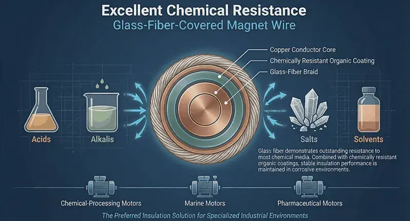
Enamel impregnation layer (insulating enamel impregnation and thermosetting to form a dense, hard surface, sealing the gaps between glass fibers). The multi-layer structure creates a synergistic effect: conductor bearing, enamel coating primer insulation, glass fiber spatial structure support, and enamel impregnation layer sealing air gaps and providing waterproofing and moisture protection. The glass fiber layer provides thermal stability and mechanical strength, while the enamel coating layer provides chemical resistance and surface smoothness, forming an organic-inorganic composite system with a “skeleton and muscle” structure. Micro-etching of the conductor surface (Ra 0.5–2 μm) enhances the adhesion of the enamel coating; a Cu–O–Si chemical bonding interface (5–10 μm thick) is formed between the glass fiber and the enamel coating, improving interlayer bonding strength.
Fundamental Differences Between enameled wire and Paper Tube Wire
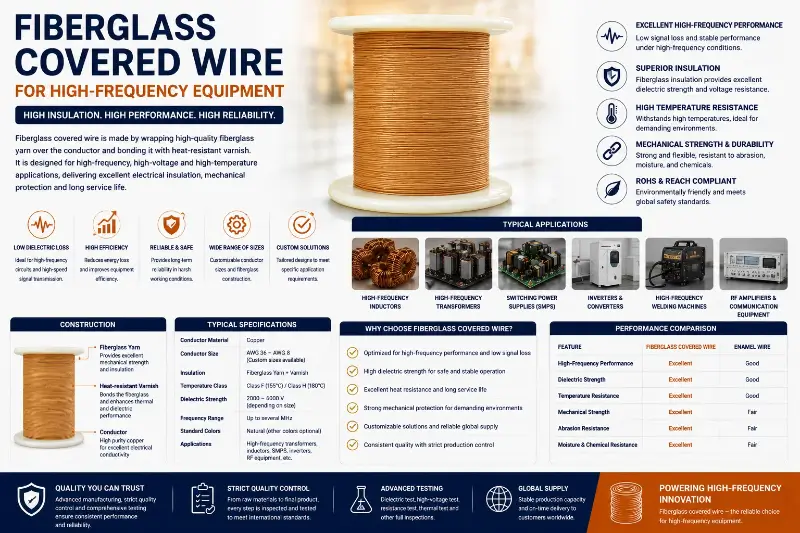
| Comparison Dimension | Enameled Wire | Paper-Covered Wire | Fiberglass Insulated Wire |
|---|---|---|---|
| —— | —— | —— | —— |
| Main Insulation | Organic insulating varnish | Cellulose paper tube | E-glass fiber + varnish impregnation composite |
| Softening Point | 200–400°C | 130–220°C | 800–1000°C (inorganic main body) |
| Breakdown Voltage | 1.5–6.0 kV rms | 2.5–16.0 kV | 5.0–15.0 kV (thick insulation ≥15 kV) |
| Dielectric Strength | 30–60 kV/mm | 30–40 kV/mm | 90 V/0.001 inch (MW 41-C) |
| Fire Rating | Not fireproof | UL 94 V-2 | UL 94 V-0 |
| Impact Resistance | Weak | Weak | Strong (glass fiber reinforced) |
| Flexural Performance | Excellent | Excellent | 1d–15d mandrel does not crack |
Core Advantages
Advantage 1: High Softening Point and Intrinsic Safety
. The core insulation material of glass fiber insulated wires is glass fiber, with its main chemical component being silicon dioxide (SiO₂) (content ≥ 54%), supplemented with oxides such as CaO / Al₂O₃ / B₂O₃ / MgO to form an alkali-free E-glass formula. The content of alkali metal oxides (Na₂O + K₂O) is < 0.8% (to avoid electrochemical corrosion). The E-glass has a softening point as high as 800°C–1000°C, far exceeding the softening point of most organic insulation materials (200–400°C). This means that glass fiber insulation will not soften, melt, or thermally decompose at normal operating temperatures (≤ 240°C), and can maintain stable insulation performance in extreme high-temperature scenarios. Under short-term overload at 1000°C (such as a short circuit in an electric arc furnace transformer), glass fiber can maintain structural integrity for 30–60 seconds, far exceeding the instantaneous breakdown of enameled wire. This fundamental difference gives glass fiber insulation irreplaceable engineering value in high-temperature applications such as traction motors, wind power, nuclear power, and electric arc furnace transformers. According to ASTM D338 glass fiber tensile strength testing, the tensile strength of a single filament E-glass fiber is as high as 3,000–4,500 MPa (diameter 6–9 μm), far exceeding the tensile strength of Q235 steel (≈ 400 MPa) and copper (≈ 220 MPa). The specific strength of glass fiber reaches 1,500–2,000 kN·m/kg, which is 5–10 times that of steel and 10–20 times that of copper. This mechanical advantage gives glass fiber insulation a natural support under mechanical stress scenarios such as vibration, impact, and short-circuit electrodynamics.
Advantage Two: Wide Thermal Rating System
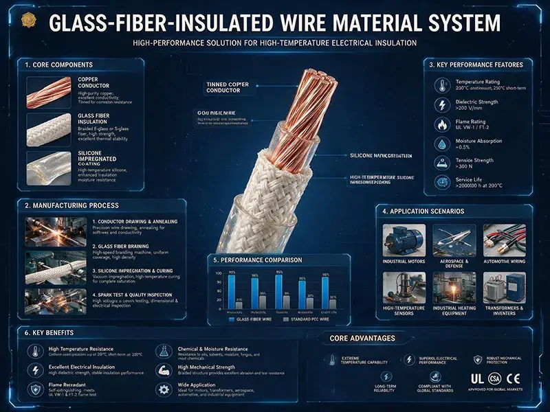
By selecting different impregnating insulating varnishes, glass fiber insulated wires can achieve a wide thermal rating coverage from Class B (130°C) to Class C (240°C+):
Class B (130°C): Polyester resin impregnation varnish, suitable for general high-temperature environments;
Class F (155°C): Modified polyester/polyurethane impregnation varnish (corresponding to NEMA MW 41-C / IEC 60317-48 standards);
Class H (180°C): Silicone resin impregnation varnish or polyester/imide impregnation varnish (corresponding to MW 44-C / MW 47-C), suitable for high-temperature industrial motors and dry transformers;
Class C (200°C–240°C+): Special silicone resin or polyimide impregnation varnish, suitable for extremely high-temperature environments (corresponding to MW 50-C / MW 51-C). According to Montsinger’s rule of thumb, for every 10 K reduction in motor winding operating temperature, insulation life approximately doubles. Class H (180°C) offers a 5-fold lifespan extension compared to Class B (130°C), and Class C (220°C) offers a 4-fold extension compared to Class H (180°C). This exponential increase in lifespan gives glass fiber insulation an overwhelming advantage in long-life applications such as wind power (≥20 years), nuclear power (≥40 years), and rail transit (≥long-term operation).
Advantage Three: High Breakdown Voltage and Dielectric Strength
. The breakdown voltage of glass fiber insulated wires is typically between 5,000V and 15,000V, with thick-insulation products reaching over 15,000V. The composite insulation structure formed by the glass fiber braided layer and impregnated varnish effectively disperses the electric field, improving the overall breakdown voltage. NEMA MW 41-C Section 3.8.4 specifies the minimum dielectric breakdown voltage for glass-insulated wires (taking 4/0-9.5 AWG as an example):
Single layer coverage ≥ 170 V;
Double layer coverage ≥ 315 V;
Products containing enamel coating should have the breakdown voltage of the corresponding enamel coating added. For stator windings of 6 kV and above high-voltage motors and PWM inverter-driven motors with high du/dt impulse voltages, the multi-layer dielectric structure of glass-insulated wires can effectively suppress partial discharge (PD) and improve the safety margin of the insulation system. The dielectric strength of glass-insulated wires (90 V/0.001 inch) is significantly higher than that of ordinary enameled wires (30–60 V/0.001 inch), and the withstand voltage per unit thickness is increased by 1.5–3 times. This allows for thinner insulation at the same breakdown voltage, improving slot fill factor and power density. Regarding dielectric constant, the dielectric constant ε_r of glass fiber insulated wire (including silicone resin impregnation varnish) is approximately 3.5 (@ 1 MHz), comparable to that of enameled wire (PE ≈ 3.0, PAI ≈ 4.0), but with a steeper dielectric gradient and a more uniform electric field distribution. In variable frequency motor drive (VFD 1–5 kV/μs du/dt) scenarios, the multilayer structure of glass fiber insulation can effectively attenuate the dv/dt impulse voltage, reducing the risk of overvoltage and insulation breakdown in the terminal windings.
Advantage Four: High Insulation Resistance and Low Loss
At room temperature (20°C), the insulation resistance of high-quality glass fiber insulated wire is typically no less than 1,000 MΩ·km; at high temperatures (155°C), the insulation resistance can still remain above 50 MΩ·km. High insulation resistance effectively reduces current leakage, improving equipment operating efficiency and safety. The low loss tangent (tan δ ≤ 0.01) and inorganic stability of glass fiber enable glass fiber insulation to maintain low dielectric loss in high-frequency (kHz–1MHz) and high-voltage environments, making it suitable for medium and high-voltage motor/transformer wiring. In 50 Hz power frequency scenarios, the dielectric loss tangent (tan δ) of glass fiber insulated wires is typically ≤ 0.01 (@ 20°C), ≤ 0.05 (@ 155°C), and ≤ 0.10 (@ 200°C), significantly lower than that of ordinary enameled wire (PE tan δ ≈ 0.05 @ 20°C, PAI tan δ ≈ 0.07 @ 20°C). In high-frequency scenarios of 1 kHz–1 MHz, the dielectric constant of glass fiber insulation remains stable (ε_r ≈ 3.5 ± 0.5), and tan δ remains within the range of ≤ 0.02, which is far superior to the sharp increase in tan δ at high frequencies (tan δ ≥ 0.10 @ 100 kHz) of enameled wire. This advantage gives glass fiber insulation irreplaceable engineering value in high-frequency applications such as VFD-driven motor, switched reluctance motor, frequency converter, and induction heating. Regarding volume resistivity, the volume resistivity ρ_v of glass fiber insulated wire is ≥ 10¹⁴ Ω·cm at room temperature (20°C), ≥ 10¹¹ Ω·cm at 155°C, and ≥ 10¹⁰ Ω·cm at 180°C, conforming to the volume resistivity test methods of IEC 60093 and ASTM D257. This parameter is significantly superior to paper-insulated wire (room temperature ρ_v ≈ 10¹²–10¹³ Ω·cm) and enameled wire (PE room temperature ρ_v ≈ 10¹³–10¹⁴ Ω·cm, PAI room temperature ρ_v ≈ 10¹⁴–10¹⁵ Ω·cm).
Advantage Five: Superior Mechanical Strength
Motor windings withstand combined mechanical stresses during manufacturing and operation, including:
bending and tensile stresses during winding and shaping;
frictional and compressive stresses during end binding;
vibration and impact stresses during operation. The glass fiber layer provides mechanical support to the windings, making glass fiber insulated wire significantly superior to pure enameled wire in all four dimensions of bending, tension, impact, and abrasion. NEMA MW 41-C Sections 3.3.8 and 3.3.2 stipulate that the glass fiber coating must not crack to expose bare copper or enamel coating after bending the mandrel from 1d to 15d. The glass fiber layer should be able to withstand ≥ 30 steel needle abrasions (round wire / flat wire), and the glass fiber adhesion should not come off. This series of clauses directly verifies the mechanical reliability of glass fiber insulation during winding manufacturing.
Advantage Six: Chemical and Environmental Resistance
Glass fiber insulated wires possess excellent chemical and environmental resistance, covering the following dimensions:
Oil Resistance: High-quality glass fiber insulated wires do not experience a decrease in breakdown voltage after immersion in transformer oil (mineral oil, synthetic ester) for 168 hours, making them naturally suitable for oil-immersed transformer applications.
Solvent Resistance: Glass fiber insulated wires show no insulation degradation after immersion in standard solvents (xylene, acetone), and can withstand impregnation processes and chemical cleaning.
Moisture Resistance: After 48 hours at 85°C / 85% RH, the insulation resistance still meets the standard (≥100 MΩ·km), suitable for humid environments (wind power, outdoor substations, mining, marine).
Salt Spray Resistance: After 96 hours of neutral salt spray testing (IEC 60068-2-52), the glass fiber layer does not crack or peel off, suitable for offshore wind power, ship propulsion, and island substations.
Advantage Seven: Fire Resistance and Intrinsic Safety
Glass fiber is a non-combustible material with excellent flame-retardant properties. Under high-temperature flame conditions, glass fiber insulated wires will not burn, release toxic gases, or produce molten droplets, effectively preventing the spread of flames. According to the UL 94 flame retardant test, glass fiber insulated wires typically achieve a V-0 rating (the highest flame retardant rating), meeting the stringent flame-retardant requirements of building electrical equipment, rail transit, and marine applications. In scenarios requiring low smoke and halogen-free (LSZH) insulation, glass fiber insulation combined with inorganic silicone resin impregnation varnish can achieve zero halogen and zero toxic smoke release, meeting standards such as EN 45545-2 HL3 level (rail transit) and IEC 60754-1/2 (low smoke and halogen-free cables).
Advantage 8: Manufacturing Process Maturity
The manufacturing process of glass fiber insulated wires is standardized and scaled up. The main process flows include:
Conductor Pretreatment (stretching, annealing, surface cleaning, annealed elongation ≥ 30%);
Optional enamel coating (painting, baking, curing; 4–8 coats; die gap 1.2–1.5 × target enamel coating thickness; coating speed 10–80 m/min);
Glass Fiber Winding (alkali-free E-glass fiber yarn spiral winding, 1–2 layers; winding angle 80°–110°; winding tension 1.5–30.0 N; winding speed 20–60 m/min);
Insulating Varnish Impregnation (immersion in a varnish bath or roller coating, varnish viscosity 0.5–2.0 Pa·s @ 25°C; impregnation time 1–5 min);
Thermosetting (stepwise heating: 80–120°C low-temperature pre-curing for 30 min →
Online Inspection (laser diameter gauge with 0.1 μm accuracy, AQL sampling 100% continuity testing, PDIV online inspection). Key equipment includes vertical and horizontal wire wrapping machines from brands such as MAG (Austria), Procond (Italy), Setic (Germany), KANDA (Japan), and STELGER (Switzerland), as well as enamel tanks, ovens, laser diameter gauges, continuity testing instruments (wet method 30V DC or dry method 100V DC enamel coating continuity), and AOI appearance inspection instruments. The process is highly standardized, and packaging requirements (moisture-proof packaging, batch number, specifications, production date) are specified in Section 30 of IEC 60317-0-6:2020. In terms of winding speed, it boasts industry-leading levels: 80–120 m/min for round wire and 30–50 m/min for flat wire, far exceeding the 2–5 m/min of hand-wrapped wire.
Advantage Ten: Engineering Advantages in Selection Decisions
Selection decisions for glass fiber insulated wires are based on established standards and criteria, far surpassing the “experience-based selection” of enameled wire and paper-insulated wire. Selection engineers can refer to international/national standards such as IEC 60317-0-6/-48/-71, NEMA MW 1000-2018 Part 2, GB/T 7672.4/.5, and JIS C 3202, systematically selecting wires based on key parameters such as thermal rating, breakdown voltage, bending radius, and AQL sampling. UL 1446 EIS (Electrical Insulation System) certification ensures the compatibility of glass fiber insulation with auxiliary materials such as insulating varnish, binding tape, insulating paper, and sleeves, avoiding systemic failures caused by selecting a single material. The engineering advantages of this selection decision are also reflected in:
Calculability — Thermal life can be accurately calculated according to the IEC 60216 Arrhenius model and Montsinger’s rule;
Testability — Standardized testing methods (IEC 60851-3/4/5/6, NEMA MW 1000 Part 3) ensure controllable quality for each batch;
Traceability — Batch number, production date, raw material source, and process parameters are fully recorded;
Comparability — Key indicators such as breakdown, thermal aging, and mechanical strength can be directly compared between different manufacturers using the same models.
Advantage Nine: Cost and Lifecycle Economics
The unit price of glass fiber insulated wire (approximately 5–30 RMB/kg, 2025 Chinese market) is higher than that of ordinary enameled wire (approximately 0.5–3 RMB/kg), but its lifecycle economics have significant advantages:
Initial investment premium is 2–5 times higher, but lifespan is extended 3–10 times;
Maintenance costs are reduced by 30–50% (less downtime, less replacement);
Total cost of ownership (TCO) is reduced by 20–40%. In long-life applications such as Class H (180°C) dry-type transformers, Class C (200°C+) nuclear power, and wind power high-heat-dissipation windings, the economics of glass fiber insulation are significantly better than enameled wire.
International Standards and Regulatory Compliance
Comparison of Five Major Standard Systems
| Standard | Scope | Key Considerations |
|---|---|---|
| —— | —— | —— |
| **IEC 60317-0-6:2020** | Glass fiber wound insulating bare or enameled round copper wire | General requirements, dimensions, breakdown, thermal aging |
| **IEC 60317-48** | Class F glass fiber yarn-covered round copper wire | MW 41-C corresponding international standard |
| **IEC 60317-71:2020** | Polyester glass fiber wound insulating bare or enameled round copper wire with temperature index 180 | TI ≥180, flexibility, softening breakdown resistance |
| **NEMA MW 1000-2018 Part 2** | MW 41-C / 44-C / 47-C / 50-C / 51-C fiberglass insulated wire series | US market standard |
| **GB/T 7672.4/.5** | Glass fiber covered winding wire | Chinese national standard |
Key Testing Requirements:
AC 2.5–3.5 kV / 1 min / No breakdown, leakage current < 1 mA;
DC 1.5–3.0 kV / 1 min / No breakdown, no arc;
Short-time test 3.5–5.0 kV / 3 sec / No instantaneous breakdown;
Thermal shock 250°C / 1h / No cracking, delamination;
Long-term thermal aging 155°C / 5000h Performance retention ≥ 50% (Class 180) / 180°C / 3000h Performance retention ≥ 50% (Class 180).
Global Compliance Requirements
| Market | Mandatory Certification | Key Standards | Special Requirements |
|---|---|---|---|
| —— | ——— | ——— | ——— |
| **EU** | CE / EN 60317 series | IEC 60317-0-6/-48/-71 | RoHS 2.0 / REACH SVHC |
| **USA** | UL 1446 / UL 758 | NEMA MW 1000-2018 Part 2 | Electrical Insulation System (EIS) |
| **China** | CCC / GB/T 7672 | GB/T 7672.4/.5 | China Electric Power Research Institute certification |
| **Japan** | PSE / JIS C 3202 | JIS C 3202 | JIS Marking Certification |
| **IEC International** | IEC 60317 series | IEC 60317-0-6/-48/-71 | Internationally applicable |
Application Scenarios and Selection Decision Framework
Twelve Major Application Scenarios
| Scenario | Thermal Class | Impregnation Varnish | Application Model | Key Indicators |
|---|---|---|---|---|
| —— | ——– | ——– | ——– | ——— |
| **Rail Transit Traction Motor** | Class H 180 / C 200 | Silicone / Polyimide | MW 44-C / 50-C | IEC 61373 Cat 1 Class B vibration |
| **Wind Power (Onshore/Offshore)** | Class H 180 / C 220 | Silicone / Polyimide | MW 47-C / 51-C | IEC 60068-2-52 96h salt spray |
| **Nuclear Power Conventional Island** | Class H 180 / C 220 | Silicone / Polyimide | MW 44-C / 50-C | ≥40 years lifespan / LOCA compatible |
| **Dry-type Transformer (Distribution)** | Class F 155 / H 180 | Modified polyester / Silicone | MW 41-C / 44-C | Breakdown ≥ 5 kV / Flame retardant V-0 |
| **High-voltage Motor ≥ 6 kV** | Class F 155 / H 180 | Modified polyester / Polyesterimide | MW 41-C / 44-C | Breakdown ≥ 15 kV / PDIV ≥ 3.0×Un |
| **Electric Arc Furnace Transformer** | Class H 180 / C 220 | Polyimide + high silicone | MW 47-C / 51-C | Surge current 10–20×In / Short-time overload |
| **PWM Inverter-Driven Motor** | Class H 180 | Silicone / Polyimide | MW 44-C | IEC 60034-18-41 / IEC 61934 PDIV |
| **Mining Motor** | Class H 180 / C 200 | Silicone / Polyimide | MW 44-C / 50-C | IEC 60079 explosion-proof / MT mining |
| **Marine Drive Motor** | Class H 180 / C 220 | Silicone / Polyimide | MW 47-C / 51-C | IEC 60068-2-52 96h / IEEE 45 |
| **Household Oven / Water Heater** | Class F 155 / H 180 | Modified polyester / Silicone | MW 41-C / 44-C | IEC 60335-1 / RoHS 2.0 |
| **Reactor / Inductor** | Class H 180 / C 220 | Silicone / Polyimide | MW 47-C / 51-C | Breakdown ≥ 10 kV / Heat dissipation |
| **Aerospace** | Class H 180 / C 220+ | Polyimide / Special silicone | Custom models | RTCA DO-160 / MIL-STD-810 |
Step-by-step Selection Decision Framework
- Scenario Determination: Define the application scenario (rail transit/wind power/nuclear power/dry-type transformer/high-voltage motor/electric arc furnace/mining/marine/home appliances/reactor/aerospace) 2. Thermal Rating Matching: Determine Class B/F/H/C based on operating temperature, peak temperature, and thermal life gradient 3. Coating System Selection: Select modified polyester/silicone/polyimide based on chemical resistance, oil resistance, and flame retardant requirements 4. Standard System Classification: Select the corresponding NEMA MW / IEC 60317 / GB/T 7672 / JIS C 3202 system according to the target market (EU / USA / China / Japan / IEC International). 5. Testing and Verification for Decision-Making: Confirm the selection based on ISO 2859-1 AQL 1.0 Level II sampling (critical defect AQL 0.65 / major defect AQL 1.0 / minor defect AQL 2.5) + batch destructive testing (AC/DC breakdown, thermal shock, long-term thermal aging, oil resistance, chemical resistance).
Three Typical Application Case Studies
Case 1: Upgrade of the Stator Winding of a 1.5 MW Onshore Wind Turbine Generator A 1.5 MW double-fed induction generator (DFIG) originally used Class F (155°C) enameled round wire (PEI enamel coating), which had been in operation for 8 years. After this period, the stator winding breakdown rate exceeded 15% (industry average 5%), with annual maintenance costs reaching 800,000 yuan. After switching to Class H (180°C) MW 44-C glass fiber insulated round wire (silicone resin impregnated varnish), the winding operating temperature decreased from 145°C to 125°C (a reduction of 20 K, extending lifespan by approximately 4 times according to Montsinger’s law), the expected lifespan increased from 15 years to long-term operation (close to the design lifespan of wind power), the breakdown rate decreased from 15% to below 2%, and annual maintenance costs decreased by 70% to 240,000 yuan. Case 2: 10 kV Dry-Type Distribution Transformer Replacement Solution A certain 10 kV / 2.5 MVA dry-type distribution transformer originally used Class F (155°C) Nomex 410 paper-insulated wire. After 12 years of operation, the insulation breakdown rate increased to 8%. After switching to Class H (180°C) MW 44-C glass fiber insulated flat wire (polyester imide varnish) + VPI vacuum pressure impregnation process, the winding breakdown voltage increased from 18 kV to 25 kV (an increase of 39%), the dielectric loss factor tan δ decreased from 0.025 to 0.015 (a decrease of 40%), the temperature rise decreased from 95 K to 70 K (a decrease of 26%), and the expected lifespan increased from 20 years to 35 years. Case 3: 600 V Household Oven Heating Element A certain 600 V / 1500 W household oven heating element originally used Class H (180°C) silicone rubber wire. After 5 years of operation, the aging and cracking rate was 30%. After switching to Class C (220°C) MW 50-C glass fiber insulation round wire (polyimide impregnation varnish), the aging cracking rate was reduced to 0%, and the breakdown voltage retention rate was ≥ 80% after continuous operation for 5000 hr (208 days) @ 220°C, which meets the UL 758 / IEC 60335-1 household appliance safety standard, and the overall lifespan of the oven was extended from 5 years to 10 years.
Selection Misconceptions and Engineering Recommendations
Common Selection Misconceptions
| Misconception | Consequence | Correct Practice |
|---|---|---|
| —— | —— | ——— |
| **Over-insulation** | Volume +30%, cost +40%, poor heat dissipation | Select the thinnest applicable solution by voltage class |
| **Inappropriate thermal class** | Class B used in Class H scenario → lifespan < 5 years | Determine class by operating temperature + 18 K margin |
| **Coating system incompatibility** | Modified polyester + polyimide mixed → chemical reaction | Select matching coating system end-to-end |
| **Incorrect winding angle** | Angle < 80° → cracking; > 110° → detachment | Keep winding angle within 80°–110° |
| **Improper impregnation/curing** | Insufficient impregnation → air gaps → breakdown; over-curing → brittleness | Stepwise temperature ramp + precise immersion time |
| **Incomplete certification** | No UL 1446 / IEC 60317 / GB/T 7672 system certification | Full system certification + third-party lab |
Engineering Recommendations
- Class F (155°C) MW 41-C preferred for general industrial scenarios, offering the best cost-performance ratio. 2. Class H (180°C) MW 44-C / 47-C for high-temperature scenarios (rail transit, wind power, high-voltage motors). 3. Class C (200°C+) MW 50-C / 51-C for extremely high-temperature scenarios (nuclear power, special industries). 4. Batch sampling ISO 2859-1 AQL 1.0 Level II sampling, batch ≥ 100% critical defect detection. 5. System certification UL 1446 EIS (Electrical Insulation System) + IEC 60317 / GB/T 7672 Two-factor authentication.
Testing Methods and Quality Control
Five Testing Dimensions
Electrical Testing: Breakdown Voltage (AC/DC), Insulation Resistance, PDIV, tan δ, enamel coating continuity
Mechanical Testing: Tensile Strength, Elongation, Springback Angle, Bending, Adhesion, Scraping Strength
Thermal Testing: Solvent Resistance, Thermal Shock, Softening Breakdown Resistance, Thermal Cycling, Long-Term Thermal Aging
Chemical Testing: Oil Resistance, Chemical Resistance, Moisture Resistance, Salt Spray Resistance, Alcohol Resistance
Dimensional Measurement: Conductor Diameter, Core Diameter, Outer Diameter, Eccentricity, enamel coating thickness
AQL Sampling Plan
| Defect Class | AQL | Inspection Frequency | Inspection Level |
|---|---|---|---|
| ——— | —– | ——— | ——— |
| **Critical defects** (breakdown, coating continuity, conductor breakage) | 0.65 | 100% online | — |
| **Major defects** (dimensional out-of-tolerance, adhesion) | 1.0 | AQL 1.0 Level II | II |
| **Minor defects** (surface blemishes, color variation) | 2.5 | AQL 2.5 Level II | II |
Key Test Parameters and Criteria
Breakdown Voltage: Single-layer coverage ≥ 170 V, Double-layer coverage ≥ 315 V (MW 41-C 4/0-9.5 AWG), 800 V @ 1.0 mm glass fiber wrapped enameled wire (IEC 60317-0-6 General Requirements), Grade 2 enamel coating + double-layer glass fiber 1.0 mm breakdown ≥ 2,000 V, AC test 2.5–3.5 kV / 1 min / leakage < 1 mA, DC test 1.5–3.0 kV / 1 min / no arc, short-time test 3.5–5.0 kV / 3 sec / no instantaneous breakdown.
Thermal Shock Resistance: 250°C / 1 hr / rapid cooling to room temperature / no cracking or delamination, breakdown voltage drop ≤ 20%.
Long-Term Thermal Aging: Class 155 5,000 hr performance retention ≥ 50%, Class 180 3,000 hr performance retention ≥ 50%, Class 200 2,000 hr performance retention ≥ 50%.
Softening Breakdown Resistance: Class 130 ≥ 170°C, Class 155 ≥ 200°C, Class 180 ≥ 220°C, Class 200 ≥ 240°C, Class 220 ≥ 260°C.
Oil Resistance: Immersion in transformer oil (mineral oil/synthetic ester) 100°C / 168 hr / breakdown voltage drop ≤ 10%.
Chemical Resistance: Immersion in xylene for 24 hours / breakdown voltage drop ≤ 15%; immersion in acetone for 24 hours / breakdown voltage drop ≤ 15%.
Moisture Resistance: 85°C / 85% RH / 48 hours / insulation resistance ≥ 100 MΩ·km.
Salt Spray Resistance: IEC 60068-2-52 96 hours neutral salt spray / glass fiber layer does not crack or peel off.
Scratch Resistance: Steel needle scratch strength ≥ 30 times (round wire / flat wire).
Adhesion: Tape peel test / glass fiber layer does not peel off.
Glass Fiber Insulation and Emerging Application Trends
New Energy Vehicles and Rail Transit Drive
Global New Energy Vehicle (NEV) Sales to Reach 17 Million Units in 2024 (YoY +25%). The 800V high-voltage platform for drive motors places new demands on winding insulation:
High du/dt tolerance (≥ 5 kV/μs);
High power density (≥ 5 kW/kg);
Long lifespan (≥ 15 years/300,000 km). Class H (180°C) MW 44-C glass fiber insulated wire, combined with IEC 60034-18-41 anti-PD design, can meet the dual challenges of NEV Class 200+ operating temperature and high du/dt. In the rail transit sector, high-speed trains such as the CR450 use Class C (200°C+) MW 50-C glass fiber insulation for their drive motors, ensuring a long-term design life and handling frequent start-stop cycles (≥ 10⁶ cycles). Regarding energy storage systems and renewable energy applications, global new energy storage capacity is projected to reach 70 GWh (YoY +60%) by 2024. The connection between PCS boost transformers and battery clusters places new demands on winding insulation:
higher frequency (kHz–MHz);
higher power density;
longer lifespan (≥ 15 years). Class H (180°C) MW 44-C glass fiber insulation flat wire + VPI impregnation technology offers overwhelming advantages in PCS boost transformers and high-frequency isolation transformers. In the offshore wind power sector, HVDC converter stations with a single unit capacity of 12–18 MW utilize Class C (220°C) MW 51-C glass fiber insulation (round wire) + polyimide impregnation to withstand long-term operation of marine corrosion (salt spray + lightning + vibration).
Smart Manufacturing and Industry 4.0
Supporting smart manufacturing and Industry 4.0, the rapid development of industrial robots, collaborative robots, and humanoid robots is being driven. Global industrial robot sales reached 500,000 units in 2024 (YoY +10%), and humanoid robot sales are expected to reach 1 million units by 2030. Requirements for robot joint motors (servo motors, harmonic reducer motors):
High power density (5–10 kW/kg);
High torque density (5–10 N·m/kg);
Short-time overload capacity of 5–10 ×. Class H (180°C) MW 44-C Glass filament insulated round wire + flat wire (cross-sectional area 30–60 mm²) for 5–10 × short-time peak torque scenarios.
Engineering Economics Analysis of Selection Decisions
Life Cycle Cost (LCC) Model
The life cycle cost (LCC) model for glass fiber insulated wires should consider the following key factors:
Initial Investment C_cap: Unit price × quantity used; glass fiber insulation is approximately 2–5 times that of enameled wire
Operating Cost C_op: Copper loss, iron loss, and maintenance costs; glass fiber insulation reduces copper loss by 10–20% in high-temperature scenarios
Maintenance Cost C_maint: Downtime losses and replacement costs; the maintenance cycle for glass fiber insulation is extended by 2–4 times
Retirement Cost C_disp: Recycling and processing costs; glass fiber insulation is 100% recyclable (copper + glass fiber + varnish)
Failure Loss C_fail: Breakdown losses and associated losses; the breakdown rate of glass fiber insulation decreases by 50–80%
LCC = C_cap + C_op + C_maint + C_disp + C_fail, calculated over a long-term lifespan:
- Glass fiber insulation LCC approximately 1.0 times the baseline
- Enameled wire LCC approximately 1.2–1.5 times the baseline (increased maintenance and failure costs)
- Paper-insulated wire LCC approximately 1.3–1.8 times the baseline (significantly increased maintenance and failure costs)
Conclusion: Glass fiber insulation exhibits significantly better LCC than enameled wire and paper-insulated wire in long-life, high-temperature, and high-reliability scenarios.
Conclusion
Multi-Dimensional Golden Rule
Glass fiber insulated wires, with their composite insulation system of inorganic glass fiber + organic varnish impregnation, possess irreplaceable engineering advantages in the following dimensions:
High softening point 800–1000°C, inherently safe
Class B–C (130–240°C+) wide thermal rating, long life (exponential life extension)
Chemical environment resistance (oil/solvent/moisture/salt spray)
UL 94 V-0 fire retardancy + LSZH inherent safety
Mechanical strength 1d–15d bending without cracking + single-wire tensile strength 3,000–4,500 MPa
Engineers should follow the Step-by-step Golden Rule when selecting wires:
Scenario determination
Thermal rating matching
Varnish system selection
Standard system classification
Testing and verification for decision-making
Glass fiber insulation has an overwhelming advantage over enameled wire and paper tubing in Class F/H/C applications, making it the preferred winding wire for high-temperature, high-pressure, high-humidity, high-vibration, and high-fire-resistance applications. For Class B (below 130°C) applications, ordinary enameled wire is sufficient, and the 2–5× cost premium of glass fiber insulated wire is not cost-effective. However, for Class F (above 155°C) applications, especially long-life applications exceeding 5,000 hours, the life-cycle economics of glass fiber insulation are significantly better than enameled wire and paper tubing, making it an irreplaceable engineering choice.