


Use of Fiberglass Covered Wire in Dry-Type Transformers
Introduction
Dry-type transformers utilize air or solid insulating media instead of transformer oil to achieve both electrical insulation and heat dissipation, and are widely applied in distribution networks, industrial plants, commercial complexes, rail transit systems, and new-energy power stations—environments with stringent requirements for fire resistance, explosion protection, and environmental safety. Glass-fiber-covered magnet wire serves as a critical insulated conductor type for dry-type transformer windings; its insulation performance, thermal class rating, mechanical strength, and flame-retardant characteristics directly determine the operational reliability, temperature rise, short-circuit withstand capability, and service life of dry-type transformers. This article focuses specifically on “Application of Glass-Fiber-Covered Magnet Wire in Dry-Type Transformers,” systematically addressing: engineering requirements imposed by dry-type transformer insulation systems on glass-fiber-covered magnet wire; intrinsic material properties of glass-fiber-covered magnet wire systems; manufacturing processes tailored for dry-type windings; performance advantages of glass-fiber-covered magnet wire over alternative insulation types in dry-type applications; representative application cases; and engineering practices for material selection—thereby providing design engineers, winding manufacturing engineers, and procurement technical evaluators with a technically grounded, engineering-referenceable framework.
Insulation System Requirements for Dry-Type Transformers with Fiberglass-Covered Windings
Operating Environment of Dry-Type Transformers
The operating environment of dry-type transformers differs fundamentally from that of oil-immersed transformers. Oil-immersed transformers rely on mineral or vegetable oil to provide high dielectric strength and efficient heat dissipation, whereas dry-type transformers depend on solid insulation or air as the insulating medium and achieve heat dissipation via natural convection or forced-air cooling. This difference in insulating media imposes higher requirements on magnet wire insulation regarding thermal endurance, flame retardancy, chemical resistance, and environmental adaptability. Under normal conditions, windings are subjected to power-frequency operating voltage superimposed with short-duration lightning impulse and switching impulse over voltages; steady-state operating temperatures typically reach 130°C to 180°C according to insulation class, while hot-spot temperatures may reach 150°C to 220°C; the operating environment exposes windings directly to ambient air, subjecting them to humidity, dust, corrosive gases, and ultraviolet radiation; fire safety requirements are stringent—winding materials must exhibit low smoke emission, low toxicity, flame retardancy, and self-extinguishing properties; mechanically, windings must withstand operational vibration, short-circuit electromagnetic forces, and transportation-induced vibration.
Insulation Class and Maximum Temperature Rise Requirements
Insulation classes for dry-type transformers are primarily defined by the maximum permissible hot-spot temperature of the winding, with common classes including Class B (130°C), Class F (155°C), and Class H (180°C); high-end applications employ Class N (200°C) or Class R (220°C). Each insulation class corresponds to specific allowable temperature rise limits: Class F permits an average temperature rise of 100 K and a hot-spot temperature rise of 115 K; Class H permits an average temperature rise of 125 K and a hot-spot temperature rise of 145 K. Temperature rise control constitutes a core design parameter for dry-type transformers, directly influencing the intrinsic selection of winding insulation materials. As a critical carrier of winding insulation, fiberglass-covered magnet wire must match the overall transformer insulation class; otherwise, it becomes a performance bottleneck, limiting the transformer’s overall capability.
Functional Role of Fiberglass-Covered Magnet Wire in Dry-Type Windings
Fiberglass-covered magnet wire serves multiple functions within dry-type windings: electrical insulation, mechanical protection, thermal support, and flame-retardant barrier. Electrically, the fiberglass braid combined with impregnating varnish forms a high-voltage-resistant composite dielectric, providing turn-to-turn, layer-to-layer, and ground insulation for the winding. Mechanically, the fiberglass braid significantly enhances the wire’s resistance to abrasion, cutting, and impact, protecting against mechanical damage during winding manufacture and operation. Thermally, the fiberglass itself exhibits excellent high-temperature stability, enabling long-term operation above 250°C and providing foundational thermal support for high-temperature-class windings. As a flame-retardant barrier, fiberglass—an inorganic non-metallic material—is inherently non-combustible and non-supportive of combustion, maintaining winding structural integrity under fire conditions.
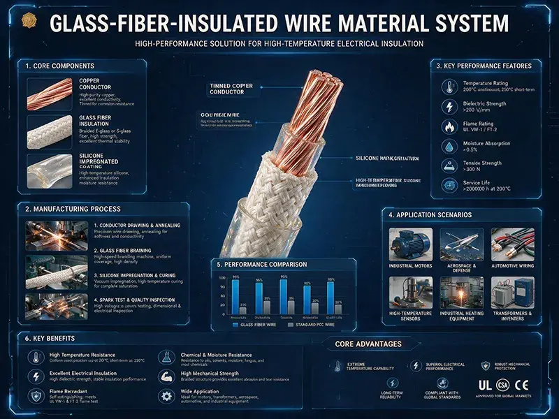
Glass-Fiber-Insulated Wire Material System
Glass Fiber Yarn Structure and Properties
Glass fiber is the core structural material of fiberglass-covered magnet wire, produced by high-speed drawing of molten glass into continuous filaments, followed by twisting, plying, and braiding to form yarns for insulation wrapping. Its chemical composition is predominantly silicon dioxide, supplemented with aluminum oxide, boron oxide, calcium oxide, and magnesium oxide; precise formulation enables tailored performance characteristics. Filament diameter typically ranges from 5 μm to 13 μm, with individual filament tensile strength reaching 2000 MPa to 4000 MPa—significantly exceeding that of steel wire and organic fibers. The thermal resistance of glass fiber constitutes its fundamental advantage for dry-type transformer insulation: melting temperature ranges from 800°C to 1000°C, and long-term operating temperature exceeds 250°C, while maintaining dimensional stability and mechanical integrity at elevated temperatures.
Comparison of E-Glass and A-Glass Fibers
Glass fibers are classified chemically into two principal types: E-glass (electrical-grade, alkali-free) and A-glass (alkali-containing). E-glass contains less than 1% alkali metal oxides and consists primarily of silicon dioxide, aluminum oxide, and boron oxide; it exhibits superior electrical insulation properties, mechanical strength, and water resistance, making it the preferred material for fiberglass-covered magnet wire in dry-type transformers. Its dielectric strength reaches 10 kV/mm to 20 kV/mm, volume resistivity exceeds 10¹⁴ Ω·cm, and dielectric loss factor remains below 0.01. A-glass contains over 10% alkali metal oxides; although lower in cost, its electrical performance and moisture resistance are markedly inferior, limiting its use to non-electrical applications. In dry-type transformer winding insulation, E-glass is the unequivocal mainstream choice.
Filament Diameter, Twist Level, and Braiding Structure
The structural performance of fiberglass-covered magnet wire depends on three critical parameters: filament diameter, twist level, and braiding configuration. Regarding filament diameter: finer filaments yield higher wrapping density and flexibility but exhibit reduced individual filament strength; coarser filaments provide enhanced abrasion resistance yet reduce wrapping density and flexibility. For dry-type transformers, common filament diameters range from 6 μm to 9 μm. Concerning twist level: increased twist enhances yarn tensile strength but reduces insulating layer plasticity and varnish penetration; insufficient twist results in yarn looseness. Twist levels for dry-type transformer yarns are typically controlled between 80 and 150 turns per meter. With respect to braiding configuration, winding insulation for dry-type transformers primarily employs two forms: tubular braiding and tape-type cross-winding. Tubular braiding provides full circumferential coverage, with typical braid density ranging from 8 to 15 crossover points per centimeter.
Impregnating Varnish and Bonding Material Systems
The impregnating varnish used for fiberglass-covered magnet wire is the key determinant of its overall performance. Dry-type transformer applications typically employ H-class or higher thermal-class impregnating varnish systems. Silicone varnish offers excellent thermal resistance (long-term operation at 180°C) and flame retardancy, making it a common choice for F-class and H-class dry-type transformer windings; epoxy varnish provides strong adhesion and chemical resistance but has a comparatively lower thermal limit; modified diphenyl ether varnish combines high-temperature resistance with flame retardancy and is preferred for premium dry-type transformer windings. Viscosity, solids content, gel time, and cure profile of the impregnating varnish must be precisely matched to the fiberglass-covered wire structure to ensure complete penetration of the glass fiber layer and formation of a dense, fully cured matrix.
Synergistic Effect Between Glass Fiber and Varnish
In fiberglass-covered magnet wire, glass fiber and impregnating varnish constitute a composite dielectric medium, wherein their synergistic interaction is pivotal to performance enhancement. Glass fiber provides an inorganic structural framework, conferring high-temperature resistance, flame retardancy, and mechanical strength to the winding; the varnish fills interstitial voids among glass filaments, delivering adhesion, electrical insulation, and moisture protection. The dielectric strength of the cured fiber–varnish composite typically exceeds the equivalent dielectric strength of either constituent alone—a classic “synergistic gain” effect. This synergy operates through three mechanisms: first, adsorption and curing of varnish on glass fiber surfaces significantly elevate both volume resistivity and surface resistivity of the composite; second, thorough filling of air gaps between filaments effectively suppresses partial discharge, substantially raising partial discharge inception voltage; third, stress relief imparted by glass fibers during varnish curing reduces the probability of microcrack formation, thereby enhancing long-term insulation stability.
Fundamental Distinction Between Fiberglass-Covered Wire and Other Insulation Types
Fiberglass-covered magnet wire differs fundamentally from enameled wire and paper-covered wire in both material system and application scope. Enameled wire features an organic enamel film insulation layer, typically 0.02 mm to 0.10 mm thick, offering high dielectric strength but limited thermal endurance dictated by the enamel’s thermal class—primarily suited for small- and medium-sized motors and electronic components. Paper-covered wire utilizes cellulose-based paper insulation, whose thermal capability is constrained by cellulose degradation and which exhibits poor flame retardancy—mainly applied in oil-immersed transformers. Fiberglass-covered magnet wire uniquely integrates the high-temperature resistance, flame retardancy, and mechanical strength advantages of inorganic fibers with the adhesion, moisture resistance, and electrical insulation benefits of organic varnishes, establishing it as the critical insulation form for dry-type transformers and other high-thermal-class applications.
Dry-Type Winding Manufacturing Process
Conductor Pre-treatment
Conductor pre-treatment is a critical process ensuring robust adhesion between the fiberglass-covered wire and the conductor. Conductor material is typically electrolytic copper or oxygen-free copper, with cross-sections available in round or rectangular configurations. The conductor surface must undergo rigorous cleaning and deburring to remove oil, oxide layers, and burrs, thereby guaranteeing a smooth, defect-free surface after fiberglass wrapping. The pre-treatment sequence comprises alkaline cleaning, acid pickling, water rinsing, phosphating, and drying. Phosphating forms a dense phosphate film on the conductor surface, significantly enhancing adhesion between the fiberglass-covered wire and the conductor. Pre-treated conductors must proceed immediately to the wrapping operation to prevent secondary oxidation or contamination.
Fiberglass Wrapping Process
Fiberglass wrapping constitutes the core manufacturing step for fiberglass-covered wire. Precise control of three key parameters—wrapping tension, wrapping angle, and overlap ratio—is essential during wrapping. Regarding wrapping tension: excessively low tension causes fiberglass slackness and results in a non-compact insulation layer; excessively high tension elongates and thins the fiberglass filaments, degrading insulation layer uniformity and mechanical strength. For dry-type transformer applications, fiberglass-covered wire wrapping tension is typically maintained between 0.5 N and 2.0 N per filament. With respect to wrapping angle: standard helical wrapping angles range from 30° to 60°, while crossover wrapping angles range from 60° to 90°; varying angles influence insulation layer coverage uniformity and mechanical performance. Concerning overlap ratio: the overlap between adjacent yarn tracks is generally 30% to 50%; insufficient overlap compromises insulation integrity, whereas excessive overlap wastes material. Wrapping equipment employs CNC-controlled fiberglass wrapping machines equipped with tension control, angle control, overlap control, and online defect detection capabilities.
Vacuum Pressure Impregnation (VPI) and Baking Curing
Vacuum Pressure Impregnation (VPI) and baking curing are pivotal processes for establishing the insulation performance of dry-type windings. The VPI process sequence is as follows: first, the winding is preheated and degassed in a vacuum oven at a vacuum level below 100 Pa and temperature of approximately 80°C to 100°C; then, degassed impregnating varnish is introduced under vacuum, ensuring complete submersion of the winding; subsequently, a pressure of 0.5 MPa to 1.0 MPa is applied for several hours to facilitate full penetration of the varnish into every void within the fiberglass layer; finally, pressure is released and excess varnish drained prior to entering the baking curing stage. During baking curing, strict control over the heating ramp profile, dwell time, and cooling rate is required to avoid incomplete curing or curing-induced cracks.
Dedicated Curing Profile Design for Fiberglass-Covered Wire
Curing profile design for fiberglass-covered wire is critical to dry-type winding performance, determining the degree of varnish cure and the final composite properties. A typical curing profile consists of three stages: a low-temperature stage (80°C to 120°C) lasting 2 to 4 hours, primarily for solvent removal and pre-curing; a medium-temperature stage (140°C to 180°C) lasting 4 to 8 hours, mainly for primary curing reactions; and a high-temperature stage (200°C to 220°C) lasting 4 to 8 hours, primarily for post-curing and stress relief. The total curing cycle typically spans 12 to 24 hours. Improper curing profile design may result in non-uniform curing, excessive internal stress, or varnish aging—directly compromising the dielectric performance, mechanical performance, and long-term reliability of the fiberglass-covered wire.
Performance Advantages of Glass-Fiber-Insulated Wire in Dry-Type Transformer Applications
Dielectric Strength and Insulation Margin
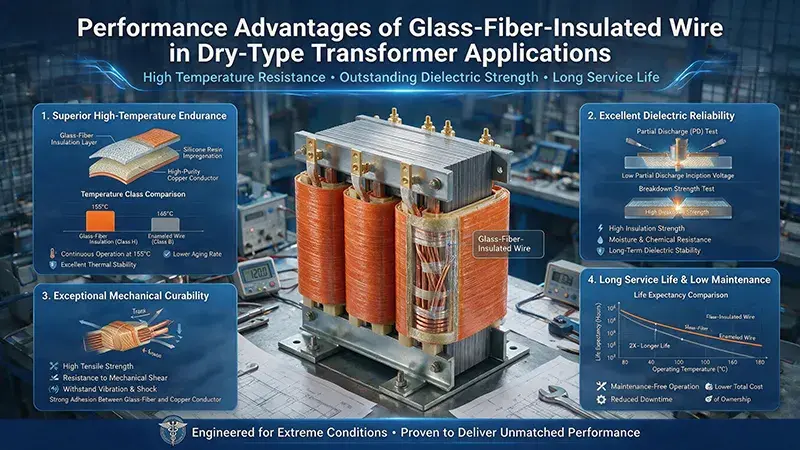
The dielectric strength of fiberglass-covered magnet wire is one of its core performance indicators for application in dry-type transformers. Typical fiberglass-covered magnet wire achieves dielectric strength in the range of 8 kV to 20 kV, depending on glass fiber braid density, impregnating varnish type, degree of cure, and conductor surface treatment quality. In dry-type transformer applications, the insulation margin of fiberglass-covered magnet wire is typically designed at 2–3 times the operating voltage to ensure no breakdown occurs under lightning impulse, switching impulse, or short-duration overvoltage conditions. Stability of dielectric strength is a key quality metric; high-quality fiberglass-covered magnet wire retains a high residual dielectric strength after accelerated aging.
Thermal Class and Long-Term Operating Temperature
The thermal class of fiberglass-covered winding wire represents a critical advantage for dry-type transformer applications. Glass fiber itself exhibits excellent inherent thermal resistance, while the thermal class of the impregnating varnish determines the overall thermal capability of the fiberglass-covered magnet wire. Common combinations include: F-class (155°C) using modified epoxy or polyester varnish; H-class (180°C) using silicone varnish or modified polyester-imide varnish; N-class (200°C) and R-class (220°C) using modified diphenyl ether varnish or specialty silicone varnish. The thermal aging life of fiberglass-covered magnet wire follows the Arrhenius relationship; H-class fiberglass-covered magnet wire has a design life exceeding 20,000 hours at 180°C, corresponding to a design service life of over 25 years for dry-type transformers operating at rated temperature.
Flame Retardancy and Self-Extinguishing Characteristics
Flame retardancy and self-extinguishing characteristics are prominent advantages of fiberglass-covered magnet wire in dry-type transformer applications. Glass fiber, being an inorganic non-metallic material, is inherently non-combustible and non-supporting of combustion, releasing no combustible gases under fire conditions. The impregnating varnish must also possess flame-retardant properties; common H-class impregnating varnishes—such as silicone varnish and modified diphenyl ether varnish—exhibit oxygen indices exceeding 30 and self-extinguish upon removal of flame. Fiberglass-covered magnet wire demonstrates three key fire-performance characteristics: non-combustibility, non-propagation of flame, and minimal emission of toxic gases. These attributes have enabled widespread adoption of fiberglass-covered magnet wire in personnel-dense environments and locations with stringent fire-safety requirements.
Mechanical Strength and Short-Circuit Withstand Capability
Mechanical strength is a significant advantage of fiberglass-covered magnet wire in dry-type transformer applications. The fiberglass braid layer substantially enhances the conductor’s tensile, compressive, flexural, and shear resistance. Dry-type transformer windings must withstand radial and axial electromagnetic forces during short-circuit events, requiring insulated conductors with sufficient mechanical integrity. Fiberglass-covered magnet wire exhibits far superior short-circuit withstand capability compared to enameled wire and bare copper wire. Key parameters include peel strength, flexural strength, tensile strength, and impact toughness. High-quality fiberglass-covered magnet wire typically achieves peel strength exceeding 50 N/cm, enabling it to withstand instantaneous high-current impacts under short-circuit test conditions.
Moisture Resistance and Chemical Stability
Moisture resistance and chemical stability represent practical advantages of fiberglass-covered magnet wire in dry-type transformer applications. Glass fiber, as an inorganic material, is inert toward moisture and most chemicals; the cured varnish film formed by the impregnating varnish acts as a barrier against moisture and chemical agents; overall, fiberglass-covered magnet wire performs markedly better than enameled wire in humid, acidic/alkaline, and oil-mist environments. When dry-type transformers operate underground, in tunnels, outdoors, or within industrial plants—environments characterized by high humidity or corrosivity—fiberglass-covered magnet wire provides reliable and stable insulation performance.
Selection Among Fiberglass-Covered Wire, Enameled Wire, and Paper-Covered Wire in Dry-Type Transformers
In dry-type transformer applications, each of these three insulation types serves distinct use cases. Enameled wire is suitable for small-to-medium capacity, low-voltage dry-type transformers but is limited in thermal class and flame retardancy; paper-covered wire is applicable to oil-immersed transformers—not dry-type applications; fiberglass-covered magnet wire dominates in large-capacity, high-voltage, high-thermal-class dry-type transformers, particularly in epoxy-cast and VPI dry-type transformers rated at F-class, H-class, or higher. In such applications, fiberglass-covered magnet wire is virtually the exclusive choice for winding insulation.
Typical Application Cases of Dry-Type Transformers with Fiberglass-Covered Windings
Epoxy Resin Cast Dry-Type Transformers
Epoxy resin cast dry-type transformers are typically employed in distribution networks and high-rise buildings at voltage levels ranging from 10 kV to 35 kV and capacities from 100 kVA to 10 MVA. The windings of such transformers are wound with fiberglass-covered wire and then fully encapsulated with epoxy resin. The fiberglass-covered wire serves as a reinforcing skeleton for the epoxy resin, while the epoxy resin provides dual functionality—moisture and dust protection, as well as mechanical and electrical insulation—for the windings. The composite material formed by the combination of fiberglass-covered wire and epoxy resin exhibits significantly superior mechanical strength, thermal stability, and flame retardancy compared to either constituent material alone. Typical applications include traction substations for urban rail transit, commercial real estate distribution transformers, and industrial park power transformers.
Vacuum Pressure Impregnation (VPI) Dry-Type Transformers
Vacuum pressure impregnation (VPI) dry-type transformers are typically employed in industrial power distribution and new-energy power stations at voltage levels ranging from 10 kV to 110 kV and capacities from 100 kVA to 50 MVA. The windings of such transformers are wound with fiberglass-covered wire and subsequently subjected to full VPI treatment; the impregnating varnish penetrates the fiberglass layer and cures to form an integral insulation system. A key distinction between VPI dry-type transformers and epoxy resin cast transformers lies in their repairability—faulty windings can be re-impregnated and restored without requiring replacement. Commonly used impregnating varnishes include H-class silicone varnish or modified diphenyl ether varnish. Typical applications include wind farm pad-mounted transformers, photovoltaic (PV) substation step-up transformers, and underground mine transformers.
Open-Type Ventilated Dry-Type Transformers
Open-type ventilated dry-type transformers are typically employed in industrial and civil distribution systems at voltage levels ranging from 0.4 kV to 10 kV and capacities from 50 kVA to 2500 kVA. The windings of such transformers are wound with fiberglass-covered wire, impregnated, and then operated in ambient air, relying on natural convection or forced-air cooling for heat dissipation. Open-type ventilated dry-type transformers feature simple construction and convenient maintenance; however, their moisture and dust resistance is comparatively weak, rendering them suitable only for relatively clean indoor environments.
Specialized Dry-Type Applications
Fiberglass-covered wire finds extensive application across multiple specialized dry-type transformer domains. In traction transformers, electrified railways and urban rail transit impose extremely stringent requirements regarding vibration resistance, overload capability, and flame retardancy; fiberglass-covered wire windings significantly enhance winding reliability and service life. In photovoltaic and wind-power applications, new-energy power station transformers demand high weather resistance, low losses, and long-term reliability; the adoption rate of fiberglass-covered wire windings in new-energy-specific dry-type transformers continues to rise steadily. In marine and offshore engineering applications, fiberglass-covered wire exhibits excellent resistance to salt fog and humidity, making it suitable for marine dry-type transformers. In electric furnace and rectifier applications, high-current handling, surge resistance, and high-temperature endurance constitute core requirements; fiberglass-covered wire windings can withstand the frequent short-circuit surges encountered in electric furnace transformers.
Selection and Engineering Implementation
Selection by Voltage Class
Selection of fiberglass-covered wire by voltage class shall be determined based on both the transformer’s rated voltage and insulation level. For voltage classes up to and including 10 kV: the typical braid density is 8–10 crossover points per centimeter, and a single-layer braid suffices; for 35 kV: braid density increases to 12–15 crossover points per centimeter, with double-layer braiding adopted in certain applications; for 110 kV: braid density and number of layers are further increased, and composite insulation structures incorporating insulating paper or film are employed. Higher voltage classes necessitate increasingly complex insulation structures for fiberglass-covered wire, along with stricter requirements for insulation thickness and mechanical strength.
Selection by Capacity Range
Selection of fiberglass-covered wire by capacity range shall be determined based on both transformer capacity and short-circuit impedance. For small-capacity transformers (≤ 1000 kVA), standard fiberglass-covered wire meets requirements; for medium-capacity transformers (1000 kVA to 10000 kVA), high-density fiberglass-covered wire combined with a premium impregnating varnish system is used; for large-capacity transformers (≥ 10000 kVA), specialty fiberglass-covered wire—such as double-layer braided or cross-wound configurations—is employed together with H-class or N-class impregnating varnish. Larger capacity ranges impose higher requirements on both the insulation structure and mechanical strength of the fiberglass-covered wire.
Specialized Quality Acceptance for Fiberglass-Covered Wire
Quality acceptance of fiberglass-covered wire constitutes a critical step in ensuring the reliability of dry-type transformer windings. Acceptance tests include: visual inspection to verify uniform braid coverage, absence of damage or contamination; geometric dimensions—including conductor diameter, overall diameter of the fiberglass-covered wire, and braid density; dielectric strength, assessed via breakdown voltage testing per IEC 60851 and GB/T 7672; impregnating varnish properties—including viscosity, solids content, gel time, and cure profile; adhesion strength between the fiberglass covering and conductor—including peel strength and flexural strength; and thermal class verification—confirmed via accelerated aging tests to validate design service life. Any nonconformities identified during quality acceptance must be traced back to the relevant manufacturing process and corrected.
Conclusion
Glass-fiber-covered magnet wire serves as the core insulating medium for dry-type transformer windings. Its composite structure—comprising inorganic glass fibers and organic impregnating varnish—offers significant advantages across multiple performance dimensions, including dielectric strength, thermal class rating, mechanical strength, flame retardancy, and chemical stability. The operating environment, insulation class, and maximum temperature rise of dry-type transformers determine the required thermal class and braiding structure of glass-fiber-covered magnet wire; the yarn construction of the glass fiber, the impregnating varnish system, and the synergistic interaction between glass fiber and varnish constitute the intrinsic determinants of the overall performance of glass-fiber-covered magnet wire; while the glass-fiber winding process and the VPI (vacuum pressure impregnation) curing process are critical manufacturing steps governing the final performance of dry-type windings. Epoxy casting, VPI, and open-type ventilated dry-type transformers represent the principal application scenarios for glass-fiber-covered magnet wire. As dry-type transformers evolve toward higher voltage ratings, greater capacity, and extended service life, glass-fiber-covered magnet wire will continue to advance innovatively in material systems, manufacturing processes, and performance optimization—providing increasingly robust technical support for high-reliability operation of dry-type transformers.