


Enameled copper wire, as a key basic material for motors, transformers, household appliances, and industrial electrical equipment, must withstand rapid temperature changes during operation—cold shocks during motor startup, instantaneous high temperatures during winding short circuits, and repeated temperature rises and falls during impregnation and drying. The thermal shock test is the core test item for evaluating the crack resistance of enameled copper wire under sudden temperature changes, and is a crucial link in insulation class determination, enameled coating formulation selection, and product quality control. This article systematically describes the standard system, test methods, criteria, typical failure modes, and engineering applications of thermal shock testing for heat-resistant enameled copper wire.
Physical Meaning of Thermal Shock Test
The enamel coating of enameled copper wire is composed of organic polymer materials, and there is a significant difference in the coefficient of thermal expansion between the metallic copper conductor and the organic enamel coating. The coefficient of thermal expansion of copper is approximately 17 × 10⁻⁶/°C, while the coefficient of thermal expansion of typical enamel coatings (polyester, polyimide, polyamide-imide) is usually in the range of 30-80 × 10⁻⁶/°C. When the temperature changes drastically, the dimensional changes of the copper conductor and the enamel coating are inconsistent, resulting in significant internal stress within the enamel coating. As the temperature decreases, the enamel coating contracts more than the copper conductor, and the enamel coating bears tensile stress; as the temperature increases, the enamel coating expands more than the copper conductor, and the enamel coating bears compressive stress. When the internal stress exceeds the tensile strength of the enamel coating, microcracks or even macroscopic cracks will appear.
Thermal shock testing simulates the extreme stress state of windings under rapid temperature changes, evaluating the ability of the enamel coating to maintain its integrity during repeated temperature cycles. The test results directly reflect the toughness, adhesion, thermal expansion matching, and heat aging resistance of the enamel coating. For heat-resistant enameled copper wire, thermal shock testing is one of the key criteria for distinguishing different insulation classes, such as F (155°C), H (180°C), C (200°C), and R (220°C).
Thermal shock testing and thermal endurance testing together constitute a complete system for evaluating the heat resistance performance of enameled wire. Thermal endurance testing evaluates the chemical stability (thermal life) of the enameled coating at long-term high temperatures, while thermal shock testing evaluates the mechanical integrity of the enameled coating under sudden temperature changes. Both are equally important in the IEC 60085 insulation class assessment, but their physical meanings differ: the former focuses on the time dimension, while the latter focuses on the rate of temperature change.
International Standard System
The thermal shock test standards for heat-resistant enameled copper wire mainly include three major systems: IEC international standards, NEMA North American standards, and GB Chinese national standards. There are mutual references and correspondences between these standards.
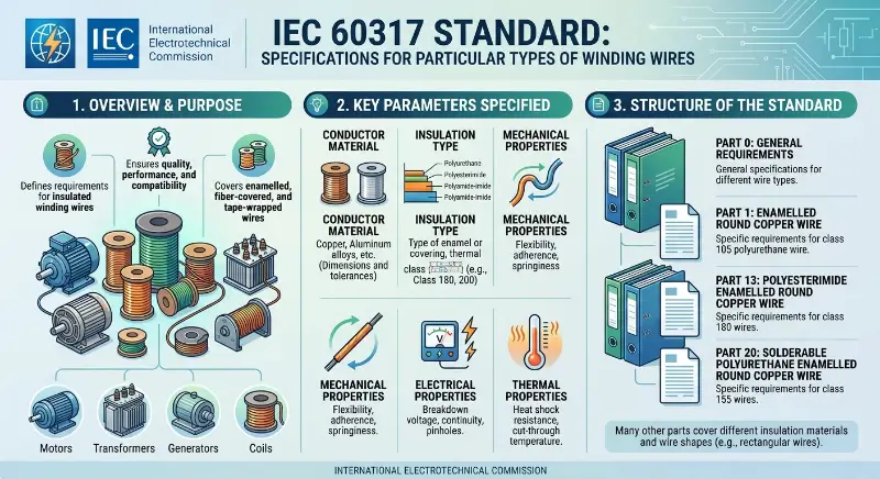
The IEC 60851 series is the foundational standard for testing methods of winding wires. IEC 60851-6, “Winding wires – Test methods – Part 6: Thermal properties,” specifically specifies the thermal shock test method. IEC 60851-6 specifies the sample preparation, test temperature, winding diameter, holding time, test procedure, and result evaluation method for thermal shock testing. The IEC 60317 series of product standards for various types of enameled wires references IEC 60851-6, specifying concrete thermal shock performance requirements for enameled wires.
NEMA MW 1000-2018 is the North American standard for winding wires. Part 3 Clause 3.5 specifies the heat shock test method. The heat shock test procedure in MW 1000-2018 is as follows: the sample is tightly wound a certain number of turns on a winding bar of a specified diameter, placed in an oven at a specified temperature for a specified time (usually 30 minutes), removed, cooled to room temperature, and the enamel coating is inspected for cracking. NEMA MW 1000-2018 specifies the heat shock temperature requirements for specific enameled wire types through the various specifications tables in Part 2 (such as MW 15-C, MW 35-C, MW 73-C, etc.).
The GB/T 7095 series comprises China’s national standards for testing methods of winding wires. GB/T 7095.6-2018, “Test Methods for Winding Wires – Part 6: Thermal Properties,” corresponds to IEC 60851-6 and specifies the detailed procedures for thermal shock testing. The GB/T 6109 series of standards for various winding wire products are equivalent to the IEC 60317 series, indirectly specifying thermal shock performance requirements.
ASTM D-1676 is a standard from the American Society for Testing and Materials (ASTM), primarily used for evaluating the long-term thermal aging of insulating materials, and has low relevance to thermal shock testing. JIS C 3003 is a Japanese Industrial Standard (JIS), specifying test methods for enameled wire, which includes thermal shock testing.
Test Sample Preparation
Sample preparation for thermal shock testing is fundamental to the validity of the test results. The pretreatment conditions, winding parameters, and selection of specifications for the test samples must all be strictly performed according to the standards.
Sample pretreatment is the first step in thermal shock testing. IEC 60851-6 specifies that samples must be placed under standard environmental conditions (temperature 15-35°C, relative humidity 45-75%) for a sufficient time (usually 24 hours) to stabilize the enamel coating before testing. For tests requiring the determination of the hygroscopic effect of the enamel coating, samples must also be pretreated under controlled humidity. Inadequate pretreatment may affect test results due to unstable internal stress states.
The sample length is determined based on the conductor diameter and the number of test turns. IEC 60851-6 specifies that the sample length should meet the requirement of at least 10 turns on the winding rod (some standards require 5 or 20 turns). For example, for a 0.5mm diameter enameled wire, the minimum length required to wind 10 turns on a 5mm winding rod is approximately 157mm (10×π×5mm). Including the lead length, the total sample length is typically 200-300mm.
The mandrel diameter is one of the key parameters in thermal shock testing. IEC 60851-6 typically requires the mandrel diameter to be a multiple of the enameled wire diameter (1×d, 2×d, 3×d, 5×d, 10×d), with different mandrel diameter requirements corresponding to different enameled wire types. The smaller the mandrel diameter, the greater the tensile strain the enamel coating withstands, and the more stringent the test. Table 1 lists the typical thermal shock mandrel diameter requirements for enameled wires.
Table 1 Typical winding diameter for thermal shock tests of enameled wire
| Type of enameled wire | Insulation class | Winding diameter | Test temperature |
|---|---|---|---|
| Polyvinyl acetal (MW 15-C) | Class 105 | 3×d | 175°C |
| Polyvinyl acetal (Class 120) | Class 120 | 3×d | 155°C |
| Polyurethane (UEW) | Class 130 | 3×d | 155°C |
| Polyester (PEW) | Class 130 | 3×d | 155°C |
| Polyester imide (PEI) | Class 180 | 2×d | 175°C |
| Polyamide imide (PAI) | Class 220 | 1×d | 220°C |
| Polyester imide/PAI double coating | Class 200 | 1×d | 200°C |
| Polyimide (PI) | Class 240 | 1×d | 240°C |
Test Procedures and Conditions
The standard procedure for thermal shock testing includes sample preheating, winding, heat treatment, cooling, and result evaluation.
Winding is a critical operation in thermal shock testing. Winding should be performed under standard environmental conditions, using specialized winding equipment (such as a manual or electric winding machine) to tightly wind the sample onto a winding bar with constant tension. The winding speed should be moderate; too fast a speed may cause mechanical damage, while too slow a speed may lead to stress relaxation. After winding, the sample should be secured to the winding bar to prevent it from springing back and loosening.
Heat treatment is the core step in thermal shock testing. IEC 60851-6 specifies that the wound sample, along with the winding rod, is placed in an oven preheated to a specified temperature and held for a specified time (usually 30 minutes). The oven temperature accuracy is typically required to be within ±2°C, and the temperature distribution uniformity within ±3°C. After the holding period, the sample is removed from the oven and allowed to cool naturally to room temperature under standard environmental conditions.
The cooling method has a significant impact on the results of thermal shock tests. The standard specifies natural cooling, which involves placing the sample under standard environmental conditions for a sufficient time (typically 30 minutes) to allow its temperature to drop to room temperature. Forced cooling (such as water quenching or liquid nitrogen cooling) introduces additional stress, potentially leading to accelerated cracking of the enamel coating, which is inconsistent with standard test conditions. IEC 60851-6 does not permit the use of forced cooling methods in standard tests.
The results were evaluated using a visual inspection method. After cooling to room temperature, the sample was removed from the winding rod, and the surface of the enamel coating was examined for cracks using normal vision (or a 6-10x magnifying glass). A pass was determined by the absence of cracks in the enamel coating; a fail was determined by the presence of visible cracks in the enamel coating. Test results were expressed as “pass” or “fail”.
Test Temperature and Insulation Class
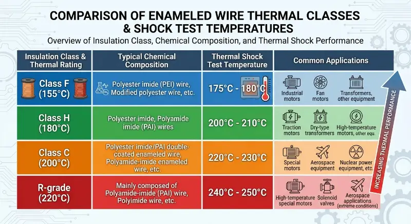
The thermal shock test temperature is directly related to the insulation class of the wire. IEC 60085 specifies the correspondence between insulation class and maximum operating temperature. The thermal shock test temperature is usually set slightly higher than the rated temperature of the insulation class to simulate temperature overload conditions.
The thermal shock test temperature for Class F (155°C) wire is typically 175°C-180°C. This class of wire includes polyester imide (PEI) wire, modified polyester wire, etc. Class F wire is widely used in industrial motors, fan motors, transformers, and other equipment.
The thermal shock test temperature for Class H (180°C) wire is typically 200°C-210°C. This class of wire includes polyester imide and polyamide imide wires. Class H wire is widely used in traction motors, dry-type transformers, high-temperature motors, and other equipment.
The thermal shock test temperature for Class C (200°C) enameled wire is typically 220°C-230°C. This class of enameled wire includes polyester imide/PAI double-coated enameled wire, polyamide-imide enameled wire, etc. Class C enameled wire is widely used in special motors, aerospace equipment, nuclear power equipment, etc.
R-grade (220°C) wire typically has a thermal shock test temperature of 240°C-250°C. This grade of wire is mainly composed of polyamide-imide (PAI) wire, polyimide wire, etc. R-grade wire is used in extreme conditions such as high-temperature special motors, solenoid valves, and aerospace applications.
Thermal shock temperatures may differ across standard systems. The NEMA MW 1000-2018 standard specifies a thermal shock temperature of 175°C for Class 105 enameled wire (MW 15-C), which does not perfectly correspond to the 155°C thermal shock temperature for Class 120 enameled wire (polyvinyl acetal) specified in IEC 60851-6. Engineers should exercise caution when comparing across standard systems, paying attention to subtle differences in insulation class definitions, test procedures, and criteria.
Typical Enamel Materials and Thermal Shock Performance
The thermal shock resistance of different enamel coating materials varies significantly. The chemical structure, glass transition temperature (Tg), coefficient of thermal expansion, and mechanical properties (elongation and fracture strength) of the enamel coating are the key factors determining its thermal shock resistance.
Polyester (PEW) enamel coating has a Tg of approximately 110-130°C and moderate mechanical properties. Under 155°C thermal shock testing conditions, it typically passes the test with a winding diameter of 3×d, but the pass rate drops significantly when the winding diameter is reduced to 2×d. Polyester enamel coating exhibits poor toughness at low temperatures and is the mainstream enamel coating for enameled wires below grade F.
Polyester imide (PEI) enamel coating has a thermal shock resistance (Tg) of approximately 180-200°C, and its mechanical properties are superior to those of polyester. Under thermal shock testing conditions of 175-180°C, it typically passes the test with a winding diameter of 2×d. Polyester imide enamel coating exhibits approximately one grade better thermal shock resistance than polyester and is the mainstream enamel coating for H-grade enameled wire.
The Tg of polyamide-imide (PAI/AIW) enamel coating is approximately 270-300°C, and its softening breakdown temperature is typically greater than 330-350°C. Polyamide-imide exhibits excellent resistance to softening breakdown and thermal shock. Even under sudden thermal shock exceeding 200°C, the internal stress of the enamel coating is extremely low, preventing cracking. Polyamide-imide is a key enamel coating material for R-grade (220°C) and C-grade (200°C) double-coated enamel wires.
Polyimide (PI) enamel coatings have a heat resistance (Tg) of approximately 350-400°C, making them the organic enamel coating with the best heat resistance. Under thermal shock testing at 240°C, polyimide enamel coatings maintain their integrity even when wound with a diameter of 1×d. Due to their superior thermal shock resistance, polyimide enamel coatings are the only choice for Class 240 enameled wire.
The polyester imide/PAI dual-coating (PEI/AIW) enamel coating combines the adhesion of polyester imide with the thermal shock resistance of polyamide imide, making it a mainstream solution for Class C (200°C) enameled wire. The outer PAI layer provides thermal shock protection, while the inner PEI layer provides adhesion support. This dual-coating structure performs excellently under 220°C thermal shock testing conditions.
Test Failure Modes and Mechanisms
Typical failure modes in thermal shock testing include enamel coating cracking, breakdown voltage drop, and loss of adhesion. Understanding these failure modes and mechanisms is fundamental to improving enamel coating formulations and processes.
Cracking of the enamel coating is the most common failure mode in thermal shock testing. Cracking types include: circumferential cracks (ring-shaped cracks along the winding direction), axial cracks (longitudinal cracks perpendicular to the winding direction), and network cracks (multi-directional intersecting cracks). Circumferential cracks are mainly caused by tensile stress and are the dominant failure mode during temperature decrease in the wound state. Axial cracks are mainly caused by localized stress concentration during the winding process. Network cracks are a combination of circumferential and axial cracks, indicating that the enamel coating has become severely embrittled.
Breakdown voltage drop is a secondary failure of thermal shock testing. Even if there are no visible cracks on the enamel coating surface, thermal shock stress can cause microcracks or localized thinning of the enamel coating, leading to a decrease in breakdown voltage. Test standards typically do not directly measure the breakdown voltage after thermal shock, but breakdown voltage testing is a supplementary verification method to thermal shock testing.
Loss of adhesion is another failure mode in thermal shock testing. Under thermal shock stress, the adhesion between the enamel coating and the copper conductor may decrease, leading to peeling or blistering of the enamel coating. This failure mode is related to factors such as the internal stress state of the enamel coating, the chemical bond strength between the enamel coating and copper, and the glass transition temperature of the enamel coating.
Factors affecting thermal shock performance include: enamel coating thickness (Grade 1 < Grade 2 < Grade 3, thicker enamel coatings have better thermal shock performance but limited improvement in breakdown voltage), enamel coating curing degree (under-curing leads to high internal stress, over-curing leads to embrittlement), enamel coating moisture absorption (wet enamel coatings are prone to cracking), conductor surface condition (surface smoothness affects adhesion), and enamel coating chemical composition (the ratio of base resin, curing agent, and additives).
Test Influencing Factors and Quality Control
The results of thermal shock tests are affected by a variety of factors, and strict control of test conditions is the basis for ensuring the reliability of test results.
The winding diameter is the most sensitive parameter in thermal shock testing. The smaller the winding diameter, the greater the tensile strain the enamel coating experiences, and the higher the risk of thermal shock cracking. Before testing, the winding rod diameter should be calibrated using a standard gauge, and worn or deformed winding rods should be avoided. The surface of the winding rod should be smooth and burr-free to avoid scratching the enamel coating.
Oven temperature uniformity is a critical control point in thermal shock testing. Temperature differences at different locations within the oven can lead to uneven heating of the samples, affecting the consistency of test results. It is recommended to place multiple temperature monitoring points inside the oven and calibrate the oven temperature regularly. IEC 60851-6 requires an oven temperature accuracy of ±2°C and a temperature distribution uniformity of ±3°C.
The holding time is another key parameter in thermal shock testing. If the holding time is too short, the enamel coating will not be sufficiently heated, resulting in inadequate test conditions; if the holding time is too long, it may lead to thermal aging of the enamel coating, resulting in non-standard test conditions. IEC 60851-6 specifies a holding time of 30 minutes, while some standards specify 1 hour or 6 hours.
The proper preparation of samples has a significant impact on test results. Samples should be carefully removed from the spool to avoid mechanical damage. Winding operations should be performed under standard environmental conditions to avoid excessively high or low temperatures affecting the enamel coating. Winding tension should be moderate to avoid excessive stretching or loosening of the enamel coating.
The skill level of the testing personnel is a subjective factor affecting the test results. It is recommended that thermal shock tests be performed by trained, dedicated testing personnel using standardized operating procedures and evaluation criteria. The laboratory should establish a statistical analysis system for test results, regularly comparing the consistency of results from different testers and with different equipment.
Engineering Applications of Thermal Shock Test
Thermal shock testing has wide applications in various engineering processes, including wire selection, insulation class assessment, coating formulation development, and equipment reliability evaluation.
The selection of enameled wire is the most direct application of thermal shock testing. Designers of equipment such as motors and transformers select enameled wires with appropriate insulation classes based on factors such as the equipment’s operating temperature, rate of temperature change, and mechanical stress. Thermal shock test results are the core basis for insulation class assessment, and designers can refer to the thermal shock performance requirements in the IEC 60317 series standards, NEMA MW 1000-2018, and GB/T 6109 series standards for selection.
Insulation class assessment is a standardized application of thermal shock testing. IEC 60085 stipulates that insulation class assessment requires a comprehensive evaluation combining thermal aging testing (temperature index TI), thermal shock testing (thermal shock temperature), and other physical performance tests. While a single thermal shock test cannot fully evaluate the insulation class of an enameled wire, it is an indispensable part of insulation class assessment.
enamel coating formulation development involves the application of thermal shock testing in research and development. During the enamel coating formulation development phase, researchers use systematic thermal shock testing to screen combinations of different base resins, curing agents, and additives, and to evaluate thermal shock performance. Thermal shock testing is typically used as the first round of evaluation in formulation screening; promising formulations are then selected for a complete insulation class assessment.
Equipment reliability evaluation is a quality control application of thermal shock testing. Manufacturers monitor product quality consistency and promptly identify quality issues such as formula fluctuations and coating process drift by conducting thermal shock tests on each batch of products. Equipment users verify product quality and prevent equipment failures due to quality problems by conducting random thermal shock tests on incoming thermal shock products.
Standard Comparison and Engineer Reference
Different standard systems have differences in thermal shock test methods in terms of test temperature, winding diameter, heat preservation time, and criteria. Engineers need to select the appropriate standard according to the specific application scenario.
IEC 60851-6 is an internationally recognized standard with broad coverage, widely referenced by the IEC 60317 series, GB/T 6109 series, and NEMA MW 1000-2018. The advantages of IEC standards are their comprehensive system and clear correspondence with product standards. The disadvantages are that parameter selection is relatively conservative, and the thermal shock temperature of some high-performance enameled wires may exceed the IEC standard range.
NEMA MW 1000-2018 is a North American regional standard. Its thermal shock temperature corresponds to, but is not entirely consistent with, the IEC standard. The advantage of the NEMA standard is its compatibility with the supply chains of North American equipment and material manufacturers. The disadvantage is that the correspondence with the IEC standard needs to be confirmed by consulting tables.
GB/T 7095.6 is a Chinese national standard, equivalent to IEC 60851-6. For enameled wire sold within China, the GB/T standard is a mandatory basic reference. Exported products must also meet the standard system requirements of the target market.
When comparing across standards, engineers should pay attention to: test temperature (e.g., IEC Class 200 = 220°C, NEMA Class 200 = 220°C), winding diameter (e.g., IEC 1×d = 2×d = 3×d range, NEMA fixed value), holding time (IEC 30 minutes, NEMA 30 minutes or 6 hours), criteria (IEC “no cracks”, NEMA “no cracks visible”), and sample specifications (IEC specifies round wire and flat wire separately, NEMA specifies round wire/flat wire separately).
Conclusion
Thermal shock testing is a core test for evaluating the crack resistance of heat-resistant enameled copper wire under sudden temperature changes. The three major standard systems—IEC 60851-6, NEMA MW 1000-2018 Part 3 Clause 3.5, and GB/T 7095.6—specify complete test procedures, with different thermal shock temperature requirements corresponding to different insulation classes of enameled wire. Polyester enameled wire is suitable for applications below Class F, polyester imide enameled wire is suitable for Class H applications, and polyamide-imide and polyimide enameled wires are key materials for Class R and above applications. Cracking is the main failure mode in thermal shock testing, and the failure mechanism involves factors such as internal stress, thermal expansion coefficient mismatch, embrittlement, and decreased adhesion. Strict control of test conditions such as winding diameter, oven temperature, holding time, and sample preparation is fundamental to ensuring the reliability of thermal shock test results. Thermal shock testing has wide applications in various engineering stages, including wire selection, insulation class assessment, coating formulation development, and equipment reliability evaluation. With the development of new high-heat-resistant coating materials (such as polyimide nanocomposite coatings), thermal shock testing standards are continuously evolving, moving towards higher temperatures, more stringent conditions, and more precise evaluation.