


When specifying enameled copper wire for any electrical application, dielectric strength is one of the most critical yet often underappreciated parameters. While engineers routinely consider wire gauge, thermal class, and DC resistance, the dielectric strength of the enamel insulation system determines whether the wire can withstand the voltage stresses it encounters in real-world operation. A wire with inadequate dielectric strength can fail catastrophically—causing short circuits, equipment damage, fires, and even safety hazards.
What is Dielectric Strength?
Dielectric strength is a fundamental property of insulating materials that quantifies the maximum electric field the material can withstand before electrical breakdown occurs. It is typically expressed in volts per unit thickness, most commonly volts per mil (V/mil) or kilovolts per millimeter (kV/mm). For enameled copper wire, dielectric strength describes the ability of the thin polymer enamel coating to resist electrical conduction when subjected to a voltage potential.
When the voltage stress across an insulation material exceeds its dielectric strength, the material suddenly transitions from being an insulator to being a conductor. This transition—called dielectric breakdown—can occur as a puncture through the insulation, surface flashover along the insulation surface, or thermal breakdown due to excessive heat generated by dielectric losses.
For enameled copper wire, dielectric strength is the key parameter that determines the maximum voltage the enamel insulation can safely withstand. Because the enamel layer on magnet wire is extremely thin—typically 0.0005 to 0.005 inches (12 to 125 micrometers)—the dielectric strength must be very high to provide adequate insulation in this small thickness.
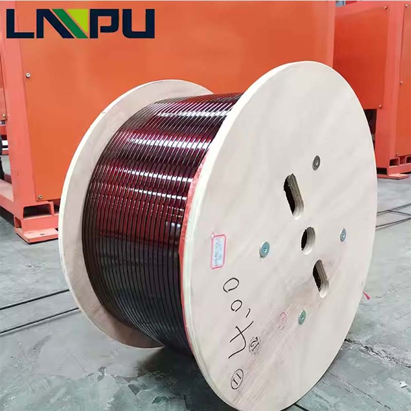
How Dielectric Strength Works in Enameled Copper Wire
The enamel insulation on a magnet wire is subjected to voltage stress in two primary ways during operation.
Turn-to-Turn Voltage Stress
In any wound coil—whether in a motor, transformer, solenoid, or inductor—adjacent turns of wire are at slightly different voltage potentials. The voltage between adjacent turns, called turn-to-turn voltage, stresses the enamel insulation locally. In a low-voltage motor winding, turn-to-turn voltage may be only a fraction of a volt, but in high-voltage windings such as those in distribution transformers, TV flyback transformers, or ignition coils, turn-to-turn voltages can reach hundreds or even thousands of volts.
Turn-to-Ground Voltage Stress
The voltage difference between any turn in the winding and the grounded frame, core, or housing creates turn-to-ground stress. This stress is highest at the turns closest to the high-voltage end of the winding, which can be the full operating voltage of the device. For a motor connected to 480V three-phase power, the turn-to-ground stress can reach 480V plus any transient overvoltages from switching or lightning.
Voltage Distribution
Voltage is not distributed evenly across the enamel coating. At sharp points, conductor edges, or areas with thin enamel coverage, the electric field intensity is much higher than in uniform regions. This is why enamel coverage uniformity, surface smoothness, and freedom from defects are critical to achieving reliable dielectric performance.
Dielectric Strength vs. Breakdown Voltage
Dielectric strength and breakdown voltage are related but distinct concepts that are often confused. Understanding the difference is essential for proper wire specification.
Dielectric Strength
Dielectric strength is a material property—specifically, the maximum electric field (V/mil or kV/mm) that an insulating material can withstand before failure. It is measured per unit thickness and does not depend on the actual thickness of the material. This makes dielectric strength useful for comparing different insulation materials and for calculating the breakdown voltage of any given insulation thickness.
Breakdown Voltage
Breakdown voltage is the actual voltage at which a specific insulation system fails. It depends on both the dielectric strength of the material and the thickness of the insulation. For enameled copper wire, the breakdown voltage is the dielectric strength multiplied by the actual enamel thickness, adjusted for any non-uniformities, defects, or environmental factors that may reduce the effective dielectric performance.
Relationship Between the Two
The relationship is straightforward: Breakdown Voltage = Dielectric Strength × Insulation Thickness. A higher dielectric strength allows the same breakdown voltage to be achieved with thinner insulation, or alternatively, a thicker insulation provides a higher breakdown voltage at the same dielectric strength. For example, a polyester enamel with a dielectric strength of 3,500 V/mil and a thickness of 1.5 mils would have a theoretical breakdown voltage of 5,250V. In practice, the actual breakdown voltage is lower due to material imperfections, surface defects, and environmental factors.
Why the Distinction Matters
When comparing enameled wires from different manufacturers, dielectric strength provides a fair comparison of the insulation material’s intrinsic quality. When specifying a wire for a particular application, breakdown voltage provides the practical voltage limit that the wire can actually withstand. Both parameters should be considered for proper wire selection.
Factors That Affect Dielectric Strength
Many factors influence the dielectric strength of enameled copper wire, ranging from the material’s intrinsic properties to manufacturing quality and operating environment.
Insulation Material Chemistry
Different enamel polymer chemistries exhibit different dielectric strengths. Polyesterimide typically provides 3,000 to 4,000 V/mil, polyamide-imide provides 3,500 to 4,500 V/mil, polyurethane provides 2,500 to 3,500 V/mil, and polyimide provides the highest dielectric strength at 4,000 to 5,000+ V/mil. Material selection should consider dielectric strength along with thermal class, mechanical properties, and chemical resistance.
Enamel Layer Thickness
Thicker enamel layers provide higher breakdown voltage but at the cost of larger overall wire diameter, reduced slot fill factor, and increased cost. The trend in magnet wire design is to achieve higher breakdown voltage with thinner enamel through improved material formulations and processing techniques.
Coating Uniformity
Any non-uniformity in the enamel coating creates a weak point where the local electric field is concentrated. Variations in thickness, pinholes, bubbles, inclusions, or foreign particles can all dramatically reduce the effective dielectric strength of the finished wire. Modern magnet wire manufacturing uses precision dies, multiple coating passes, and online inspection to ensure coating uniformity.
Conductor Surface Quality
The surface quality of the copper conductor beneath the enamel affects the dielectric strength of the finished product. A rough, dirty, or oxidized copper surface creates local stress concentrations and poor enamel adhesion, reducing the effective dielectric strength. High-quality magnet wire production begins with clean, smooth copper conductor that is properly prepared before enameling.
Manufacturing Process
The enameling process—application method, cure temperature profile, solvent removal, and number of coating passes—all influence the final dielectric strength. Proper cure is essential to achieve the full mechanical and electrical properties of the enamel polymer. Under-cured enamel is mechanically weak and has lower dielectric strength, while over-cured enamel can become brittle and prone to cracking during winding.
Temperature
Dielectric strength decreases as temperature increases. The hot dielectric strength of an enamel system is typically 50% to 70% of its room temperature value. For applications operating at elevated temperatures, the dielectric strength at the actual operating temperature—not the room temperature value—must be considered.
Humidity and Moisture
Moisture absorption reduces dielectric strength by introducing water into the insulation, which has much lower dielectric strength than the dry enamel polymer. For humid environments, moisture-resistant enamel formulations or additional protective coatings may be required to maintain adequate dielectric performance.
Frequency
At high frequencies, dielectric losses in the enamel material can cause heating and reduce the effective dielectric strength. The dissipation factor of the enamel material at the operating frequency determines how much heating occurs and how much the dielectric strength is degraded.
Mechanical Stress
Bending, stretching, and impact during winding can create micro-cracks or thin spots in the enamel that reduce dielectric strength. The ability of the enamel to withstand mechanical stress without dielectric degradation is called its “wound dielectric strength” and is typically lower than the as-coated dielectric strength.
Industry Standards and Test Methods
Dielectric strength is measured and specified according to standardized test methods that ensure consistent comparison between products and manufacturers.
ASTM D3032
ASTM D3032 is the standard test method for hookup wire insulation, including the dielectric withstand test for enameled magnet wire. This test applies an increasing voltage to the wire specimen until breakdown occurs, and the breakdown voltage is recorded.
IEC 60851
The IEC 60851 series of standards specifies test methods for winding wires, including dielectric tests. These standards are widely used internationally and provide consistent test procedures for breakdown voltage, continuity of insulation, and other electrical properties.
NEMA MW 1000
NEMA MW 1000 is the American standard for magnet wire that specifies dielectric strength requirements for various wire types and sizes. The standard defines minimum dielectric strength values that qualified wire must meet.
GB/T 7673
GB/T 7673 is the Chinese national standard for enameled winding wire, providing specifications and test methods aligned with international standards.
Test Voltage Application
Standard dielectric tests typically apply voltage at a controlled rate of increase (often 500 V/s or 1000 V/s) until breakdown occurs. Some tests use a stepwise voltage increase with hold times. The actual test conditions affect the measured value, so comparison between products requires knowledge of the specific test method used.
Pin Hole and Continuity Testing
Pin hole testing detects small defects in the enamel coating that could allow voltage breakdown at lower than expected voltages. Modern high-quality magnet wire production includes 100% online pin hole testing using high-voltage DC or AC techniques.
Typical Dielectric Strength Values
Dielectric strength values for enameled copper wire vary significantly based on the insulation material, wire size, and coating build (single, heavy, triple).
Standard Build (Grade 1)
Standard build enamel coatings typically provide dielectric strength values of 1,500 to 2,500 V per the ASTM D3032 twist pair test, depending on the insulation material and wire size.
Heavy Build (Grade 2)
Heavy build coatings, with approximately 30% to 50% more enamel thickness, typically provide 2,500 to 4,000 V in the twist pair test.
Triple Build (Grade 3)
Triple build coatings, used for the most demanding high-voltage applications, can provide 4,000 to 6,000+ V in the twist pair test.
Material-Specific Values
Polyimide enameled wire provides the highest dielectric strength among common magnet wire insulations, making it the preferred choice for high-voltage applications. Polyesterimide and polyamide-imide provide good dielectric strength with better processability and lower cost for general-purpose applications. Polyurethane provides moderate dielectric strength with the added benefit of solderability.
AWG-Specific Considerations
Smaller AWG wires (finer wire diameters) have less enamel thickness for a given build grade, which generally results in somewhat lower breakdown voltage values. However, the dielectric strength of the material itself remains the same—only the resulting breakdown voltage for the thinner coating is reduced.
Why Dielectric Strength Matters in Different Applications
The importance of dielectric strength varies across applications based on the voltage stress the wire experiences in service.
Low-Voltage Motor and Transformer Windings
Motors and transformers operating at 120V to 480V typically experience modest voltage stress on the enamel insulation. Standard build enamel with good dielectric strength is usually adequate for these applications, with safety factors of 5x to 10x over the operating voltage.
High-Voltage Motor Windings
Motors operating at 2,300V, 4,160V, or higher voltages—such as large industrial motors and high-voltage pump motors—experience significantly higher voltage stress. Heavy build or triple build enamel with high dielectric strength is required to provide adequate safety margin against insulation failure.
Distribution and Power Transformers
Distribution transformers operating at 7,200V, 13,800V, or higher primary voltages, and power transformers operating at transmission voltages, require enameled wire with high dielectric strength to withstand both steady-state voltage and transient overvoltages from lightning and switching.
Automotive Ignition Coils
Automotive ignition coils generate brief high-voltage pulses of 20,000V to 40,000V to fire spark plugs. The enameled wire used in these coils must have very high dielectric strength to withstand the peak voltage stress on each turn.
TV and Monitor Flyback Transformers
Flyback transformers in CRT televisions and computer monitors generated extremely high voltage pulses of 25,000V to 35,000V. The enameled wire in these transformers required the highest dielectric strength available to prevent insulation failure.
Medical Imaging Equipment
MRI, CT scanner, and X-ray equipment often use high-voltage transformers and coils that require enameled wire with excellent dielectric strength and long-term reliability under continuous high-voltage stress.
Switch-Mode Power Supplies
Modern switch-mode power supplies operate at high switching frequencies with fast voltage transients. The enameled wire in the high-frequency transformer windings must have adequate dielectric strength to withstand the peak voltages generated by the switching action.
Inverter-Duty Motors
Motors driven by variable frequency drives (VFDs) experience voltage spikes at the motor terminals that can be 2 to 3 times the DC bus voltage, with rise times in the microsecond range. The enamel insulation in inverter-duty motors must be specifically designed to withstand these high-voltage, high-frequency stress conditions.
How to Select Adequate Dielectric Strength
Selecting the right dielectric strength for an enameled copper wire application requires systematic evaluation of the operating conditions and safety requirements.
Determine the Maximum Operating Voltage
Calculate or measure the maximum voltage that the enamel insulation will experience in service. This includes the normal operating voltage, transient overvoltages from switching, lightning, or other sources, and any resonant voltage amplification that may occur in the winding.
Apply an Appropriate Safety Factor
Apply a safety factor of 2x to 5x to the maximum operating voltage to account for aging, manufacturing variations, environmental effects, and unforeseen conditions. For safety-critical applications, higher safety factors (5x to 10x) may be appropriate.
Consider the Operating Temperature
Use the dielectric strength at the actual operating temperature, not the room temperature value. For high-temperature applications, the hot dielectric strength of the insulation material should be the basis for design calculations.
Account for Manufacturing Variations
Specify wire with dielectric strength that is well above the minimum required value to account for normal manufacturing variations. A wire with 4,000 V typical breakdown voltage and 2,000 V minimum specification provides more design margin than a wire with 2,500 V typical and 2,000 V minimum.
Verify Through Testing
Conduct incoming inspection and qualification testing of the wire to verify that the dielectric strength meets the specified requirements. For critical applications, ongoing batch testing may be appropriate to ensure consistent quality over time.
Consider the Operating Environment
For humid, corrosive, or chemically active environments, the effective dielectric strength of the enamel may be reduced. Use moisture-resistant enamel formulations or additional protective coatings as needed to maintain adequate dielectric performance.
Evaluate Long-Term Aging Effects
Dielectric strength degrades over time as the insulation ages from thermal, electrical, and environmental stress. The expected service life of the equipment should be considered when selecting the initial dielectric strength, with adequate margin to ensure reliable operation throughout the design life.
Conclusion
Dielectric strength is a fundamental property of enameled copper wire that determines its ability to withstand voltage stress in service. While it is often overshadowed by more visible parameters like wire gauge and thermal class, dielectric strength is the key parameter that prevents electrical breakdown, short circuits, and catastrophic equipment failure. Understanding the relationship between dielectric strength, breakdown voltage, and insulation thickness enables engineers to make informed wire selection decisions that balance performance, cost, and reliability.
Across the full range of enameled copper wire applications—from small electronic coils to large power transformers—dielectric strength plays a critical role in determining equipment reliability and safety. Selecting wire with adequate dielectric strength for the operating voltage, temperature, and environment ensures that the equipment performs reliably throughout its design life without insulation failure.
When specifying enameled copper wire, give dielectric strength the careful consideration it deserves. Evaluate the operating voltage stress, apply appropriate safety factors, account for environmental and aging effects, and select wire from manufacturers with proven quality systems and comprehensive testing capabilities. The modest additional cost of high dielectric strength wire is invariably justified by the improved reliability and reduced risk of catastrophic insulation failure.