
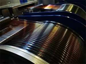
Enameled copper wire coils are fundamental components in electrical equipment, serving critical functions in motors, transformers, generators, and various electromagnetic devices. The reliability and performance of these coils directly impact the overall functionality of the equipment in which they are installed. Understanding common faults and proper maintenance procedures is essential for ensuring longevity and optimal performance. This comprehensive guide provides maintenance professionals, engineers, and equipment operators with practical knowledge about common faults encountered in enameled copper wire coils, diagnostic techniques, and maintenance procedures.
The information presented here enables effective troubleshooting and maintenance practices that extend equipment life and reduce unexpected failures. Regular maintenance and timely fault resolution significantly reduce equipment downtime and repair costs. This guide serves as a practical reference for anyone responsible for maintaining electrical equipment featuring enameled copper wire coils.
Common Electrical Faults
Insulation breakdown represents one of the most frequent faults affecting enameled copper wire coils, occurring when the enamel coating deteriorates and allows unintended electrical contact between conductors. Thermal aging causes insulation properties to degrade over time, particularly when coils operate at temperatures approaching or exceeding their thermal class ratings. The organic materials in enamel insulation slowly oxidize and become brittle, eventually cracking or flaking away. Electrical stress from voltage surges, partial discharges, or sustained overvoltage conditions accelerates insulation degradation.
Lightning strikes, switching transients, and power quality issues create stress that cumulative damage eventually exceeds the insulation withstand capability. Contamination from moisture, chemicals, or particulate matter creates conduction paths across insulation surfaces or penetrates the enamel coating at weak points. Environmental exposure in harsh operating conditions significantly accelerates this failure mechanism.
Short Circuit Faults
Short circuit faults occur when conductors that should remain electrically isolated make contact, either directly or through degraded insulation. Turn-to-turn shorts develop when adjacent turns of the same winding come into electrical contact. These faults often begin as high-resistance connections that generate localized heating, progressively degrading surrounding insulation until complete short circuits form. Phase-to-phase shorts occur between windings of different phases in multi-phase equipment.
These faults typically result from insulation failure combined with mechanical movement or contamination that creates bridging conductive paths. Ground faults involve contact between a winding and the magnetic core or equipment chassis. Grounding faults create dangerous fault currents and typically require immediate protective action to prevent equipment damage.
Open Circuit Faults
Open circuit faults interrupt current flow through the coil, preventing normal equipment operation. These faults eliminate the circuit entirely rather than creating abnormal current paths. Broken conductors result from mechanical stress, vibration fatigue, or manufacturing defects that fracture the copper wire. Repeated thermal cycling creates expansion and contraction stress that eventually cracks the conductor.
Overheating causes solder joint failures at connection points, particularly where wires are terminated to terminals or connection straps. Repeated thermal cycling loosens connections and eventually creates open circuits. Connection loosening from vibration or thermal cycling causes increasing resistance at termination points, eventually resulting in complete circuit interruption.
Common Mechanical Faults
Mechanical movement of enameled copper wire coils within their slots or cavities causes insulation damage and eventual electrical faults. Vibration during operation gradually abrades enamel insulation where wire surfaces rub against slot walls or adjacent conductors. Motor starting currents and load changes create electromagnetic forces that stress coil positioning. Electromagnetic forces during fault conditions, particularly short circuits, can cause rapid coil movement that damages insulation before protective devices operate.
Bushing or support structure failures allow coil components to shift position, creating stress concentrations that crack insulation or break conductors.
Thermal Expansion Damage
Repeated thermal cycling causes expansion and contraction that stresses coil structure and insulation integrity. Differential expansion between copper conductors and iron cores creates cyclic stress that gradually loosens coil components and damages insulation at stress concentration points. Loose coils experience greater movement during thermal cycling, accelerating the mechanical degradation process in a self-reinforcing cycle. Insulation materials have different thermal expansion coefficients than copper, creating additional stress at the interface between conductor and enamel coating.
Contamination and Corrosion
Environmental contamination attacks enamel insulation and metallic components of the coil assembly. Moisture penetration causes oxidation of exposed copper at damaged insulation points and promotes galvanic corrosion where dissimilar metals contact. Chemical contamination from industrial atmospheres, cleaning agents, or process materials degrades enamel insulation through chemical attack. Particulate contamination creates abrasive conditions that damage insulation surfaces during any movement or vibration.
Diagnostic Techniques
Visual inspection provides the first line of fault diagnosis, revealing many common problems before they cause complete equipment failure. Discoloration indicates overheating that has degraded insulation, conductor materials, or connection surfaces. Localized heating reveals high-resistance connections or abnormal current paths. Physical damage including broken ends, bulges, or deformation suggests mechanical problems or internal faults requiring further investigation.
Contamination accumulation on coil surfaces indicates environmental exposure that may have compromised insulation integrity in hidden locations.
Electrical Testing Procedures
Electrical testing confirms fault conditions and localizes problems within the coil assembly. Insulation resistance testing measures the resistance between windings and ground, revealing insulation degradation before complete failure. Low readings indicate moisture contamination, thermal damage, or chemical degradation. Turn-to-turn short testing detects degraded insulation between adjacent turns that visual inspection cannot reveal.
Surge testing or low-voltage ohmmetry identifies shorted turns through abnormal resistance readings. Inductance and resistance measurement compare against reference values to detect winding modifications, open circuits, or significant contamination affecting conductor properties.
Advanced Diagnostic Methods
Advanced diagnostic techniques provide detailed fault characterization for complex problems or root cause analysis. Partial discharge detection identifies insulation weaknesses before they cause complete failure, enabling condition-based maintenance that prevents unexpected outages. Thermal imaging during operation reveals hot spots indicating high-resistance connections, circulating currents, or abnormal magnetic forces within the coil assembly. Frequency response analysis detects mechanical deformation or contamination that changes the electrical characteristics of the winding in ways that affect equipment performance.
Maintenance Procedures
Proper cleaning removes contaminants that accelerate insulation degradation and obscure faults during inspection. Dry cleaning with soft brushes or vacuum removes loose particulate contamination without introducing liquids that might penetrate coil insulation. Solvent cleaning with appropriate solvents removes oily or greasy contamination while avoiding damage to enamel insulation. Compatibility testing ensures the solvent does not attack insulation materials.
Controlled drying after any wet cleaning or environmental exposure removes moisture before it causes damage. Baking at elevated temperatures accelerates moisture removal when necessary.
Re-insulation Repairs
Minor insulation damage can often be repaired without complete rewinding, extending equipment life at reduced cost. Slot cell repair involves replacing damaged slot liners and adding supplemental insulation between windings and the core structure. Coil bracing and wedging tightens loose coils that vibrate and cause progressive insulation damage. Proper bracing distributes electromagnetic forces across the winding structure.
End-turn coating application restores insulation integrity at coil ends where mechanical stress and contamination concentrate.
Connection Maintenance
Connection integrity is critical for reliable coil performance and is often the weakest link in the assembly. Terminal inspection and cleaning removes oxidation and contamination from connection surfaces. Torque verification ensures connections remain tight despite thermal cycling stress. Loose connections generate heat that degrades surrounding insulation.
Lead wire replacement addresses insulation brittleness or damage in the lead portion of the winding that extends beyond the core structure.
Preventive Maintenance Strategies
Environmental controls prevent contamination and moisture from degrading coil insulation. Sealing and gasketing prevent moisture and particulate entry into equipment enclosures. Dehumidification in humid environments prevents moisture accumulation within equipment. Corrosion prevention coatings protect exposed metal components from environmental attack.
Operating Parameter Control
Operating equipment within designed parameters extends insulation life and prevents premature failures. Load management prevents sustained overloading that accelerates thermal aging of insulation. Voltage regulation prevents overvoltage stress that degrades insulation incrementally over time. Temperature monitoring detects abnormal heating that indicates developing problems before failure occurs.
Inspection Scheduling
Regular inspection schedules catch developing problems before they cause equipment failure. Scheduled offline inspection allows thorough examination when equipment is de-energized and accessible. Online monitoring provides continuous assessment of operating parameters that indicate developing faults. Condition-based maintenance adjusts inspection frequency based on equipment condition and operating experience.
Motor Coil Maintenance
Motor stator windings experience specific fault patterns related to their construction and operating environment. Phase-to-phase faults develop at coil crossovers where mechanical stress and contamination concentrate. Turn-to-turn shorts occur where enamel damage or contamination creates localized conduction paths. Grounding faults develop at slot exits where sharp edges or movement can damage insulation.
Rotor Winding Faults
Rotor windings face unique challenges from rotation, centrifugal forces, and slip ring or bearing current effects. Solder joint failures from centrifugal force or repeated thermal cycling cause open circuits in rotor windings. Insulation damage from brush sparking or bearing currents creates grounds or shorts in rotor circuits. Balance weight attachment points can stress conductor insulation if not properly cushioned.
Bearing Current Damage
Bearing currents create unique fault patterns that often mimic insulation degradation. Fluting patterns in bearings indicate sustained bearing current passage that damages bearing surfaces. Insulation failure results when bearing currents find paths through bearing housings or lubrication. Grounding brush maintenance prevents charge accumulation that creates damaging discharge events.
Transformer Coil Maintenance
Transformer windings experience electromagnetic forces during faults that can permanently deform coil structure. Axial displacement shifts windings along the core leg, stressing lead connections and tap changer mechanisms. Radial buckling compresses windings inward, damaging insulation between turns and potentially creating shorts. Untanking and inspection may be necessary to assess internal winding condition after severe fault events.
Lead and Tap Changer Issues
Transformer leads and tap changers experience different stresses than the main winding. Mechanical connections in tap changers require periodic inspection and maintenance. Lead flexibility must accommodate transformer thermal expansion without developing cracks. Bushing connections require special attention to prevent moisture ingress along lead surfaces.
Oil Contamination Effects
Oil-filled transformers require oil quality monitoring to protect coil insulation. Oil analysis detects contamination that indicates developing insulation problems. Dissolved gas analysis identifies fault gases from thermal or electrical insulation degradation. Oil reconditioning or replacement restores dielectric properties when contamination is detected.
Safety Considerations
Working on enameled copper wire coils requires attention to electrical safety hazards. De-energization and lockout verification ensures equipment cannot energize during maintenance. Grounding confirms that capacitive charges cannot create dangerous voltages on accessible parts. Voltage withstand testing verifies insulation integrity before returning equipment to service.
Thermal Safety
Hot equipment creates burn hazards that require appropriate precautions. Cooling time requirements prevent burns from hot components that appear cool on surfaces. Temperature monitoring during operation identifies conditions that create hazards during maintenance windows. Thermal imaging enables hot spot identification without direct contact with heated surfaces.
Chemical Safety
Cleaning solvents and materials require appropriate handling to protect worker health. Ventilation requirements prevent vapor accumulation that creates fire or health hazards. Personal protective equipment appropriate for the specific chemicals in use protects workers during maintenance. Material safety data sheets document hazards and required precautions for all chemical materials.
Troubleshooting Quick Reference
Low insulation resistance measurements indicate insulation problems requiring investigation. Moisture contamination causes low readings that improve with drying. Bake at temperatures below insulation class limits to avoid additional thermal damage. Thermal aging causes permanent reduction in insulation resistance that cannot be reversed.
Assessment determines whether repair or replacement is appropriate. Contamination requires identification and removal of the specific contaminant affecting the insulation surface.
Abnormal Operating Temperature
Abnormal temperatures indicate problems that will shorten equipment life if not addressed. High load currents cause elevated temperatures that may indicate overloaded equipment or abnormal operating conditions. Circulating currents from imbalances or harmonic distortion create heating beyond that from normal load current. Cooling system problems including blocked vents, failed fans, or contaminated heat exchangers prevent adequate heat dissipation.
Vibration and Noise
Abnormal vibration or noise indicates mechanical problems that damage coils if not corrected. Loose coils vibrate and generate noise while progressively damaging insulation. Retightening or rebbling restores proper coil positioning. Bearing failures create vibration that transmits to coil structures and can damage lead connections or terminal connections.
Magnetic forces from electrical imbalances create that stresses coil bracing and support structures.
Conclusion
Maintenance knowledge for enameled copper wire coils encompasses understanding common fault mechanisms, diagnostic techniques, and appropriate maintenance responses. Regular inspection and testing catch developing problems early, while proper maintenance procedures address issues before they cause complete failure. The key to successful coil maintenance is combining systematic inspection with appropriate testing and timely maintenance response. Equipment reliability improves when maintenance programs address root causes rather than just symptoms, preventing recurrence of problems that shorten equipment life.
Safety considerations must guide all maintenance activities, ensuring that maintenance personnel are protected from electrical, thermal, and chemical hazards present in coil maintenance work. Effective maintenance programs extend the useful life of enameled copper wire coils, reduce unexpected failures, and optimize the total cost of equipment ownership. The investment in maintenance knowledge and procedures pays returns through improved reliability and reduced downtime.