


Enameled wire (also known as magnet wire, winding wire, electromagnetic wire, or coil wire) serves as the core conductor material for virtually all electromagnetic components—including transformers, motors, generators, inductors, relays, electromagnets, voice coils, solenoids, sensors, ignition coils, and wireless charging systems. Although its structure appears simple (a metallic conductor plus an insulating enamel coating), it is in fact a multidisciplinary integration encompassing materials science (conductor metallurgy + polymeric enamel chemistry), electrical engineering (dielectrics + skin effect + partial discharge), mechanical engineering (elastic mechanics + bending stress + frictional wear), thermodynamics (heat conduction + thermal expansion + thermal aging), chemistry (enamel curing + solvent evaporation + crosslinking reactions), and manufacturing process engineering (wire drawing + annealing + enameling + baking + coiling).
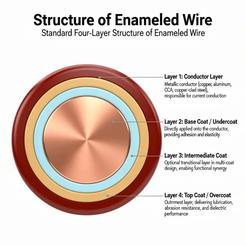
From an engineering perspective, enameled wire constitutes a multi-layer composite cylindrical shell: radially outward from the center, it comprises four distinct layers—conductor layer, base coat / undercoat / bonding layer, intermediate coat (optional), and top coat / surface coat—each fulfilling defined functional roles in materials science, with precise geometric thicknesses (typically 0.005–0.060 mm), dielectric properties (dielectric strength, loss factor, tanδ), mechanical properties (elasticity, hardness, adhesion), thermal properties (temperature rating, coefficient of thermal expansion [CTE], thermal aging life), and chemical resistance (solvent resistance, oil resistance, refrigerant resistance, acid/alkali resistance). In cross-section, enameled wire exhibits either a concentric circular geometry (round wire) or an approximately rectangular geometry (rectangular wire); round wire diameters range from 0.012–8.0 mm, wherein 0.05–0.30 mm is designated precision-instrument grade, 0.30–2.50 mm represents the mainstream motor/transformer grade, and 2.50–8.00 mm applies to large-scale power equipment.
Total enamel thickness is classified per IEC 60317, NEMA MW 1000, and GB/T 6109 into Grade 1 (thin coat, single-layer thickness 0.01–0.02 mm), Grade 2 (medium coat, single-layer thickness 0.02–0.04 mm), and Grade 3 (thick coat, single-layer thickness 0.04–0.06 mm); enamel outer diameter exceeds bare conductor diameter by 0.02–0.10 mm. This article systematically addresses: an overview of enameled wire structure and its engineering perspective; conductor layer structure and materials science (Cu, Al, CCA, Cu-clad steel; round, rectangular, Litz); base coat structure and functionality (adhesion + elasticity + dielectric performance); intermediate coat structure and functionality (multi-layer synergy); top coat structure and functionality (lubrication + protection + dielectric performance); enamel layer configuration (single-coat / double-coat / triple-coat / self-bonding layer) and temperature-class compatibility; enamel thickness grading and dimensional relationships; structural nomenclature within standard frameworks (NEMA MW 1000, IEC 60317, GB/T 6109, ASTM D1676, DIN 46435, JIS C 3202); structural failure mechanisms of enamel (pinholes, thermal aging, dielectric breakdown, mechanical cracking); interrelationships between structure and manufacturing processes (wire drawing → annealing → enameling → baking); and the mapping relationship between enameled wire structure and engineering selection criteria—providing motor engineers, transformer engineers, coil designers, enameled wire manufacturing engineers, enameled wire application engineers, and procurement engineers with a comprehensive, actionable, data-supported structural cognition framework.
Overview of Enameled Wire Structure and Engineering Perspective
Although enameled wire structure appears simple, it is in fact a highly engineered multi-layer composite system, with each layer designed for specific functional intent and purpose.
Standard Four-Layer Structure of Enameled Wire
A typical enameled wire consists of four layers radially outward (minimal model):
- Layer 1: Conductor Layer: Metallic conductor (copper, aluminum, CCA, copper-clad steel), responsible for current conduction
- Layer 2: Base Coat / Undercoat: Directly applied onto the conductor, providing adhesion and elasticity
- Layer 3: Intermediate Coat: Optional transitional layer in multi-coat designs, enabling functional synergy
- Layer 4: Top Coat / Overcoat: Outermost layer, delivering lubrication, abrasion resistance, and dielectric performance
Cross-Sectional and Longitudinal Structural Characteristics
Cross Section:
– Round wire: Perfect concentric circular geometry
– Rectangular wire: Approximately rectangular geometry; enamel thickness at rounded corners must be guaranteed
– Litz wire: Composed of multiple individually insulated strands twisted together
Longitudinal Section:
– Continuously uniform enamel coating structure
– Single enameled wire length can reach 10,000–100,000 meters
– Enamel thickness uniformity along length: ±10%
Multi-Dimensional Attributes of Enameled Wire Structure
Each layer involves multiple engineering attributes:
| Attribute | Conductor Layer | Base Coat | Intermediate Coat | Top Coat |
|---|---|---|---|---|
| Thickness (typical) | 0.5–5 mm (diameter) | 0.005–0.025 mm | 0.005–0.020 mm | 0.005–0.020 mm |
| Primary Material | Cu, Al, CCA | Polyester, Polyurethane | Polyester-imide | Polyamide-imide, Polyimide |
| Primary Function | Current conduction | Adhesion, elasticity | Synergy, transition | Abrasion resistance, lubrication, dielectric performance |
| Key Performance | Resistivity, tensile strength | Adhesion, elongation | Compatibility, miscibility | Coefficient of friction, hardness |
| Failure Modes | Overheating, open circuit | Delamination, cracking | Interlayer delamination | Abrasion, scratching |
Engineering Significance of Enameled Wire Structure
Structural rationality directly determines:
– Electrical Performance: Insulation thickness governs dielectric strength; conductor purity governs resistivity
– Mechanical Performance: Base coat adhesion dictates bendability; top coat lubricity governs winding processability
– Thermal Performance: Top coat temperature rating defines overall temperature class; conductor material governs current-carrying capacity
– Chemical Performance: Top coat chemical resistance determines suitability for specific media (oil, refrigerants, acids/bases)
– Manufacturing Process: Each enamel layer requires dedicated enameling and baking steps
– Economics: Multi-layer enamel increases material cost by 5–15%
The “4 + 1” Structural Dimensions of Enameled Wire
Understanding enameled wire structure requires mastery of the “4 + 1” dimensions:
– Material Dimension (M): What material constitutes each layer
– Thickness Dimension (T): Thickness of each layer
– Functional Dimension (F): Purpose/function of each layer
– Interface Dimension (I): Interfacial adhesion mechanism between layers
– Failure Dimension (R): Failure modes of each layer and associated interfaces
Conductor Layer Structure and Materials Science
The conductor layer is the core functional element of enameled wire, performing three critical functions: current conduction, magnetic field coupling, and mechanical support.
Conductor Material Classification
Copper Conductors (Most Common):
– Electrolytic Tough Pitch (ETP) Copper: Cu ≥ 99.90%, trace oxygen content
– Oxygen-Free High-Conductivity (OFHC) Copper: Cu ≥ 99.95%, oxygen < 10 ppm
– Tin-Coated Copper: 2–5 μm tin plating; corrosion resistance and solderability
– Nickel-Coated Copper: 1–3 μm nickel plating; high-temperature resistance
– Copper Alloys: Cu-Ag (enhanced softening resistance), Cu-Cr (increased strength), Cu-Mg
Aluminum Conductors (Weight-Sensitive Applications):
– Pure aluminum (≥99.5%)
– Aluminum alloys (Al-Mg-Si): Enhanced creep resistance
– Surface treatments: Lubricant coating or thin insulation
Copper-Clad Aluminum (CCA):
– Copper volume fraction: 10–40%
– Weight reduction vs. pure copper: 30–50%
– Cost reduction vs. pure copper: 30–60%
Copper-Clad Steel (CCS):
– Used in high-strength applications (e.g., high-frequency voice coils)
– Steel core diameter ratio: 20–50%
Conductor Geometries
Round Wire:
– Diameter range: 0.012–8.00 mm
– Precision grade: 0.012–0.05 mm (sensors, instrumentation)
– General-purpose grade: 0.05–2.50 mm (motors, transformers, inductors)
– Power-grade: 2.50–8.00 mm (large transformers, high-power motors)
Rectangular Wire / Strip:
– Thickness: 0.50–6.00 mm
– Width: 2.00–25.00 mm
– Width-to-thickness ratio: ≥1.5:1
– Corner radius: ≥0.5 mm
– Applications: Large power transformers, new-energy vehicle traction motors (hairpin), wind power generation
Litz Wire:
- Stranded fine enameled wire
- Single-strand diameter: 0.04–0.20 mm
- Number of strands: 10–1000
- Lay length: 15–50 mm
- Applications: High-frequency transformers, induction heating, wireless charging
Conductor Key Parameters
Electrical Resistivity:
- Oxygen-free copper @20°C: ≤ 0.01724 Ω·mm²/m
- Pure aluminum @20°C: ≤ 0.0282 Ω·mm²/m
- CCA 15%: ≈ 0.0250 Ω·mm²/m
- Temperature coefficient α: copper 0.00393/°C, aluminum 0.00403/°C
Mechanical Properties:
- Annealed copper tensile strength: 220–260 MPa
- Annealed copper elongation: 30–40%
- Annealed aluminum tensile strength: 70–100 MPa
- Annealed aluminum elongation: 15–25%
Tolerance Requirements (Typical):
| Diameter Range | Diameter Tolerance | Ovality |
|---|---|---|
| 0.020–0.100 mm | ±0.002 mm | ≤0.001 mm |
| 0.100–0.250 mm | ±0.003 mm | ≤0.002 mm |
| 0.250–0.500 mm | ±0.005 mm | ≤0.003 mm |
| 0.500–1.000 mm | ±0.008 mm | ≤0.005 mm |
| 1.000–2.500 mm | ±0.012 mm | ≤0.008 mm |
| 2.500–5.000 mm | ±0.020 mm | ≤0.015 mm |
Conductor Surface Treatment
Microstructure of Bare Copper Surface:
- Wire-drawing surface roughness Ra: 0.4–1.6 μm
- Surface defects: burrs, scratches, oxide scale
- Residual wire-drawing lubricant: must be thoroughly removed
Surface Pre-treatment (Prior to Enameling):
- Mechanical wiping (brushing, polishing)
- Chemical cleaning (acid pickling, alkaline cleaning)
- Plasma treatment (for high-end products)
- Ultrasonic cleaning (for precision wire)
Functions of Surface Pre-treatment:
- Enhance enamel adhesion
- Remove contaminants
- Improve enamel wettability
- Ensure uniform enameling
Base Coat Structure and Function
The base coat is the “inner foundation” of the enameled wire structure, directly contacting the conductor and fulfilling three core functions: adhesion, elasticity, and buffering.
Engineering Significance of the Base Coat
The base coat plays a “bridging” role in enameled wire:
- Downward: must bond firmly to the conductor surface
- Upward: must exhibit excellent interlayer adhesion with the intermediate or top coat
- Self: must provide elasticity, extensibility, dielectric performance, and thermal stability
Consequences of Omitting the Base Coat:
- Enamel delamination (during coil winding)
- Enamel cracking upon bending
- Enamel blistering during thermal cycling
- Enamel shedding after long-term operation
Base Coat Material Systems
Polyester (PE):
- Thermal class: Class 130/155
- Advantages: strong adhesion, good flexibility, low cost
- Limitations: moderate thermal resistance
- Applications: general-purpose motors, household appliances
Polyurethane (PU / UEW):
- Thermal class: Class 130/155
- Advantages: excellent solderability (no wire scraping required), superior high-frequency performance
- Limitations: moderate thermal resistance, moderate mechanical strength
- Applications: high-frequency transformers, relays, electronic coils
Modified Polyester:
- Thermal class: Class 155/180
- Advantages: 30 K improvement in thermal resistance while retaining adhesion
- Applications: standard motors, transformers
Polyvinyl Formal (PVF / Formal):
- Thermal class: Class 105/120
- Advantages: exceptional high-frequency performance
- Applications: high-frequency coils, radar systems
Polyamide-imide (PAI / AIW):
- Thermal class: Class 200/220
- Advantages: extremely high thermal resistance, fluorocarbon resistance
- Limitations: high cost
- Applications: Class H motors, air-conditioner compressor windings
Engineering Significance of Base Coat Thickness
Typical Thickness Ranges:
- Single-layer base coat: 0.005–0.015 mm
- Double-layer base coat: 0.010–0.025 mm
- Constitutes 20–40% of total enamel thickness
Thickness Selection Principles:
- Thin base coat (< 0.010 mm): precision wire, high-frequency applications
- Medium base coat (0.010–0.020 mm): general-purpose motors, transformers
- Thick base coat (> 0.020 mm): Class H high-temperature, harsh-environment applications
Relationship Between Thickness and Mechanical Performance:
- Base coat too thin: insufficient adhesion, prone to delamination
- Base coat too thick: reduced elasticity, prone to cracking upon bending
- Optimal range: 25–35% of total enamel thickness
Base Coat Adhesion Mechanisms
Mechanical Interlocking:
- Enamel penetrates micro-pores on conductor surface (wire-drawing texture)
- Forms “anchor” structure upon curing
- Optimal surface roughness Ra: 0.8–1.6 μm
Chemical Bonding:
- Polar groups in enamel (–OH, –COOH, –NH) form hydrogen bonds with copper oxide layer
- Copper oxide layer (Cu₂O, CuO) thickness: 5–50 nm
- Excessive oxide layer thickness degrades adhesion (over-oxidation)
- Insufficient oxide layer thickness limits bonding
Thermal Stress Matching:
- Copper CTE: 17 × 10⁻⁶/°C
- Enamel CTE: 50–150 × 10⁻⁶/°C
- Large mismatch necessitates elastic buffering by base coat
- Base coat modulus: < 1 GPa (polyester)
- Top coat modulus: > 2 GPa (polyimide)
Base Coat Failure Modes
Delamination Failure:
- Bending radius too small (< 1× wire diameter)
- Base coat–conductor adhesion strength < internal stress
- Manifestation: flake-like enamel detachment
Crazing Failure:
- Low base coat glass transition temperature (Tg)
- Base coat embrittlement at elevated temperatures
- Manifestation: network-like microcracks
Blistering Failure:
- Trapped moisture or solvent beneath base coat
- Gas expansion at elevated temperatures
- Manifestation: dome-shaped protrusions
Intermediate Coat Structure and Function
The intermediate coat serves as the “synergistic layer” within multi-layer enamel structures—not present in all enameled wires, yet critical for high-performance enameled wire.
Design Intent of the Intermediate Coat
Functional Positioning:
- Acts as a “chemical bridge” between base and top coats
- Harmonizes performance disparities between layers
- Provides additional dielectric thickness
- Enhances overall mechanical and thermal performance
Typical Scenarios:
- Composite-coated enameled wire (e.g., PEI + AIW)
- Three-layer structure (base + intermediate + top)
- Class H/C motor enameled wire
Intermediate Coat Materials
Polyester-imide (PEI / EIW):
- Thermal class: Class 180
- Advantages: excellent thermal resistance, high mechanical strength, compatibility with both polyester and polyamide-imide
- Applications: intermediate layer between polyester base coat and polyamide-imide top coat
Polyamide (PA / Nylon):
- Thermal class: Class 105–155
- Advantages: high elasticity, strong adhesion
- Applications: bonding layer in self-bonding wire
Epoxy:
- Thermal class: Class 130–155
- Advantages: exceptional adhesion, chemical resistance
- Applications: bonding layer in self-bonding wire, hot-melt bonding
Polyester-imide–polyamide-imide Copolymer:
- Integrates advantages of PEI and AIW
- Thermal class: Class 200
- Applications: high-end Class H motors
Intermediate Coat Thickness Design
Typical Thickness:
- Single-layer: 0.005–0.020 mm
- Constitutes 15–30% of total enamel thickness
Design Principles:
- Compatibility with base and top coats (gradual CTE transition)
- Provision of dielectric redundancy (30–50% increase in breakdown voltage)
- Minimal diameter increase (to avoid slot-fill ratio degradation)
Intermediate Coat Synergistic Effects
Dielectric Synergy:
- Multi-layer dielectric strength = sum of individual layers + interfacial polarization
- Electric field distortion at interfaces may become weak points for breakdown
- Optimization: graded dielectric constant design
Thermal Expansion Synergy:
- Gradual CTE transition from inner to outer: Cu (17) → base coat (80) → intermediate coat (100) → top coat (120)
- Prevents stress concentration
Mechanical Synergy:
- Graded elastic modulus: soft inner layer (< 1 GPa), hard/tough outer layer (> 2 GPa)
- Enables synchronous deformation across layers during bending
Intermediate Coat Process Challenges
Enameling Difficulty:
- Secondary enameling requires precise thickness control
- Baking temperature and time must be precisely optimized
- Clear interlayer interfaces with robust interlayer adhesion required
Typical Process:
- First coating (base coat): felt applicator, baking at 300–400°C
- Second coating (intermediate coat): felt applicator, baking at 350–450°C
- Third coating (top coat): felt applicator, baking at 400–500°C
- Total number of enameling passes: 4–10 (depending on total enamel thickness)
Top Coat Structure and Function
The top coat is the “outer garment” of magnet wire and serves as the direct interface for equipment contact, winding friction, and dielectric insulation.
Engineering Significance of the Top Coat
Functions of the top coat:
- Abrasion resistance: Withstands mechanical wear during winding and coil insertion
- Lubricity: Reduces coefficient of friction to facilitate automated winding
- Dielectric performance: Provides primary electrical insulation and voltage withstand capability
- Chemical resistance: Resists oils, chlorofluorocarbons (CFCs), acids, alkalis, and humidity
- Thermal resistance: Determines the temperature class rating of the magnet wire
- Aesthetic properties: Color, gloss, and uniformity
Top Coat Material Systems
Polyamide-imide (PAI / AIW):
– Temperature class: Class 200/220
– Advantages: Exceptional thermal stability, CFC resistance, and mechanical strength
– Limitations: High cost
– Applications: Class H motors, air-conditioning compressor windings, and new-energy vehicle traction motors
Polyimide (PI / PIW):
– Temperature class: Class 220/240
– Advantages: Ultra-high thermal stability, radiation resistance, and dielectric strength
– Limitations: High cost and poor mechanical toughness
– Applications: Class C motors, aerospace, and nuclear power systems
Modified polyester (Modified PE):
– Temperature class: Class 155/180
– Advantages: Cost-effective and flexible
– Applications: General-purpose motors and household appliances
Polyester (PEW):
– Temperature class: Class 130/155
– Advantages: Lowest material cost
– Applications: Low-end motors and electronic coils
Polyurethane (UEW):
– Temperature class: Class 130/155
– Advantages: Excellent solderability
– Applications: High-frequency transformers, relays, and electronic coils
Polyvinyl formal (PVF):
– Temperature class: Class 105
– Advantages: Extremely low high-frequency dielectric loss
– Applications: High-frequency coils and radar systems
Top Coat Thickness Design
Typical thickness:
– Single-layer top coat: 0.005–0.020 mm
– Contribution to total enamel thickness: 30–50%
Relationship between thickness and functional performance:
| Thickness | Abrasion Resistance | Dielectric Strength | Winding Ease | Cost |
|---|---|---|---|---|
| Thin (< 0.010 mm) | Poor | Medium | Easy | Low |
| Medium (0.010–0.020 mm) | Good | Good | Medium | Medium |
| Thick (> 0.020 mm) | Excellent | Excellent | Difficult | High |
Specialized Top Coat Formulations
Self-lubricating top coat:
– Incorporates wax- or silicone-based lubricants
– Reduces coefficient of friction to 0.05–0.10
– Used in high-speed automated winding
Self-bonding top coat:
– Includes thermoplastic adhesive layer (e.g., polyamide copolymer)
– Activates at 100–180 °C to form inter-turn bonds
– Applied in bobbinless coils (e.g., wireless charging receiver coils)
Corona-resistant top coat:
– Contains nano-sized SiO₂, Al₂O₃, or TiO₂ fillers
– Used in variable-frequency drive (VFD) motors and high-voltage (HV) windings
– Extends partial discharge (PD) lifetime by 10–100×
Chemical-resistant top coat:
– Specially formulated to resist chlorofluorocarbons (R22, R134a, R410a), oils, acids, and alkalis
– Applied in air-conditioning systems, chemical processing, and electrolysis equipment
Top Coat Failure Modes
Abrasive failure:
– Caused by excessive winding tension or insufficient top coat hardness
– Manifests as surface scratches or enamel breaches
Blistering/delamination:
– Results from poor intercoat adhesion between top coat and underlying layer
– Appears as flaking or sheet-like peeling
Pinhole failure:
– Arises from coating process defects
– Defined as micro-holes with diameter < 50 μm
– Rejection criterion: > 5 pinholes per 30 m
Thermal/arc erosion failure:
– Triggered by overload, overheating, or corona discharge
– Characterized by charring and carbonization
Enamel Layer Architecture and Thermal Class Matching
Enamel layer architecture constitutes the core of magnet wire structural design and determines thermal class rating, mechanical performance, and dielectric characteristics.
Single-Coat Structure
Structure:
– Conductor + monolayer enamel (integrated primer and top coat)
– Total thickness: 0.010–0.025 mm
– Number of coating passes: 3–6
Representative magnet wire types:
– Polyester enameled wire (PEW)
– Polyurethane enameled wire (UEW)
– Polyester-imide enameled wire (EIW)
Typical thermal classes:
– Polyester: 130–155 °C
– Polyurethane: 130–155 °C
– Polyester-imide: 180 °C
Dual-Coat Structure (Dual Coat / Double Coat)
Structure:
– Conductor + primer + top coat
– Total thickness: 0.020–0.040 mm
– Number of coating passes: 6–10
Typical combinations:
| Primer | Top Coat | Temperature Class | Typical Application |
|---|---|---|---|
| Polyester (PE) | Polyamide-imide (AIW) | Class 180/200 | Class H motors |
| Polyurethane (UE) | Polyamide (PA) | Class 155 | Relays and electronics |
| Polyester-imide (PEI) | Polyamide-imide (AIW) | Class 200 | Premium Class H motors |
| Modified polyester | Modified polyester | Class 180 | Standard motors |
Triple-Coat Structure
Structure:
– Conductor + primer + intermediate coat + top coat
– Total thickness: 0.030–0.060 mm
– Number of coating passes: 8–14
Typical combinations:
| Primer | Intermediate Coat | Top Coat | Temperature Class | Application |
|---|---|---|---|---|
| Polyester | Polyester-imide | Polyamide-imide | Class 200 | Premium Class H |
| Polyurethane | Polyester-imide | Polyamide-imide | Class 200 | High-frequency Class H |
| Polyester-imide | Modified polyimide | Polyimide | Class 220/240 | Class C motors |
Self-Bonding Structure
Structure:
– Standard enamel system (PE/PEI/AIW) + self-bonding top layer (PA / PA copolymer / epoxy)
– Total thickness: 0.025–0.050 mm
Function:
– Thermally activated bonding without impregnation
– Used in wireless charging, voice coils, and air-core coils
– Simplifies manufacturing processes
Composite-Coat Structure
Modern configuration:
– Nano-modified enamel
– Incorporates inorganic fillers (SiO₂, Al₂O₃, mica)
– Enhances corona resistance, abrasion resistance, and chemical resistance
Typical applications:
– Variable-frequency drive (VFD) motors: corona-resistant magnet wire
– New-energy vehicles: ATF-oil-resistant magnet wire
– High-frequency motors: low-dielectric-loss enamel
Thermal Class vs. Enamel Material System
| Temperature Class | Enamel Material System | Typical Enamel Architecture |
|---|---|---|
| Class 105 | PVF | Single-layer PVF |
| Class 130 | PEW / UEW | Single-layer PEW / UEW |
| Class 155 | Modified PEW / UEW | Single-layer modified system |
| Class 180 | EIW | Single-layer EIW or PE + EIW |
| Class 200 | EIW + AIW | Dual-coat or composite system |
| Class 220 | PEI + PI / AIW + PI | Dual-coat or composite system |
| Class 240 | PI + PI | Dual-layer polyimide |
Enamel Thickness and Geometric Considerations
Engineering selection of enamel thickness involves comprehensive trade-offs among dielectric strength, mechanical robustness, winding performance, and cost-effectiveness.
IEC 60317 Thickness Grades
Grade 1 (Thin Enamel):
– Thickness increment: 0.01–0.025 mm
– Diameter increase: 0.02–0.05 mm
– Applications: High-frequency, precision, and densely wound components
Grade 2 (Medium Enamel):
– Thickness increment: 0.025–0.045 mm
– Diameter increase: 0.05–0.09 mm
– Applications: General-purpose motors, transformers, and inductors
Grade 3 (Heavy Enamel):
– Thickness increment: 0.045–0.060 mm
– Diameter increase: 0.09–0.12 mm
– Applications: Class H/C, high-voltage, and harsh-environment applications
Relationship Between Enamel Thickness and Wire Diameter
| Bare Wire Diameter (mm) | Grade 1 Coating Thickness | Grade 2 Coating Thickness | Grade 3 Coating Thickness |
|---|---|---|---|
| 0.10 | 0.005–0.012 | 0.012–0.020 | 0.020–0.030 |
| 0.30 | 0.008–0.015 | 0.015–0.025 | 0.025–0.038 |
| 0.50 | 0.010–0.018 | 0.018–0.030 | 0.030–0.045 |
| 1.00 | 0.012–0.020 | 0.020–0.035 | 0.035–0.050 |
| 2.00 | 0.015–0.025 | 0.025–0.040 | 0.040–0.058 |
| 3.00 | 0.018–0.028 | 0.028–0.045 | 0.045–0.065 |
| 5.00 | 0.020–0.030 | 0.030–0.050 | 0.050–0.075 |
Functional Trade-offs of Coating Thickness
Advantages of Thin Coating:
– Smaller overall diameter, higher slot fill factor
– Easier wire insertion (cabling)
– Superior high-frequency performance (lower distributed capacitance)
– Lower material cost
Limitations of Thin Coating:
– Lower dielectric strength
– Reduced mechanical protection
– Higher risk of pinholes
– Faster exposure of coating defects
Advantages of Thick Coating:
– Higher dielectric strength
– Enhanced mechanical protection
– Fewer pinholes
– Extended service life
Limitations of Thick Coating:
– Lower slot fill factor
– More difficult wire insertion (cabling)
– Higher distributed capacitance (poorer high-frequency performance)
– Higher material cost
– Slightly reduced thermal dissipation
Coating Thickness vs. Dielectric Breakdown Voltage
| Total Coating Thickness | Grade 1 Breakdown Voltage | Grade 2 Breakdown Voltage | Grade 3 Breakdown Voltage |
|---|---|---|---|
| 0.015 mm | 1.5–2.5 kV | — | — |
| 0.025 mm | 2.5–4.0 kV | 4–6 kV | — |
| 0.040 mm | 4–5 kV | 6–9 kV | 9–12 kV |
| 0.060 mm | — | 9–12 kV | 12–18 kV |
Coating Thickness vs. Mechanical Properties
Flexibility Test:
– 1× mandrel: All Grades pass
– 2× mandrel: Grades 1–3 pass
– Pinhole count after winding: Grade 3 < Grade 2 < Grade 1
Adhesion Test:
– Snap test: No flaking for all Grades
– Peel test: Adhesion strength Grade 3 > Grade 2 > Grade 1
Structural Designation Across Standard Systems
Different standard systems employ distinct methods to designate magnet wire construction; understanding these standards is fundamental to correct product selection.
IEC 60317 Standard System
Structure:
– IEC 60317-X (X denotes coating type)
– e.g., IEC 60317-13 (Polyester Enamelled Round Copper Wire)
– e.g., IEC 60317-25 (Polyester-imide Enamelled Round Aluminum Wire)
Key Parameters:
– Conductor material (Copper/Aluminum)
– Coating type (PEW/UEW/EIW/AIW/PIW)
– Coating thickness grade (Grade 1/2/3)
– Thermal class
– Diameter range
NEMA MW 1000 Standard System
Structure:
– MW 1000: General specification
– Individual standards: MW 1, MW 2 … MW 86
– Nomenclature: MW + number (in chronological order of development)
Key Designators:
– MW 1-C (Copper)
– MW 1-A (Aluminum)
– MW + number + suffix (e.g., -C, -A, -J, -N)
Typical NEMA MW Standards:
| Standard Number | Coating Type | Thermal Class |
|---|---|---|
| MW 1-C | Oleo-resinous | Class 105 |
| MW 5-C | Polyester | Class 155 |
| MW 24-C | Polyurethane | Class 155 |
| MW 30-C | Polyester-imide | Class 180 |
| MW 35-C | Polyamide-imide | Class 200 |
| MW 42-C | Polyimide | Class 220 |
| MW 73-C | Polyester-imide + Polyamide-imide (Dual-coated) | Class 200 |
| MW 76-C | Modified polyester + Polyamide-imide | Class 200 |
GB/T 6109 Standard System (Chinese National Standard)
Structure:
– GB/T 6109.X
– Nomenclature analogous to IEC 60317
Typical Standards:
– GB/T 6109.1: General Requirements
– GB/T 6109.2: Polyester Enamelled Round Copper Wire
– GB/T 6109.9: Polyester-imide Enamelled Round Copper Wire
– GB/T 6109.10: Polyamide-imide Enamelled Round Copper Wire
ASTM D1676 Standard System
Structure:
– ASTM D1676: General Test Methods for Magnet Wire
– Supported by dedicated standards: ASTM D2307, D3377, D4880, etc.
Test Items:
– Dielectric breakdown voltage
– Dielectric loss tangent (tan δ)
– Pinhole count
– Winding test
– Thermal aging life
DIN 46435 / EN 60317 (European Standards)
Structure:
– Technically equivalent to IEC 60317
– Numbering system substantially identical
JIS C 3202 (Japanese Industrial Standard)
Structure:
– JIS C 3202: General Specification for Enamelled Wires
– Distinct numbering system
– Cross-referencing with IEC/NEMA requires use of official equivalence tables
Standard Cross-Reference Table (Partial)
| Coating Type | IEC | NEMA MW | GB/T | JIS | Thermal Class |
|---|---|---|---|---|---|
| Polyester | 60317-13 | MW 5 | 6109.2 | C 3202 | 155 |
| Polyurethane | 60317-19 | MW 24 | 6109.4 | — | 155 |
| Polyester-imide | 60317-23 | MW 30 | 6109.5 | — | 180 |
| Polyamide-imide | 60317-26 | MW 35 | 6109.10 | — | 200 |
| Polyimide | 60317-46 | MW 42 | 6109.6 | — | 220 |
| PEI + AIW Dual-coated | 60317-47 | MW 73 | 6109.11 | — | 200 |
Structural Designation Rules in Standards
A complete designation shall include:
– Coating material (by standard number or descriptive name)
– Coating thickness grade (Grade 1/2/3)
– Conductor material (Cu/Al/CCA)
– Conductor diameter (including tolerance)
– Packaging form (reel, drum, etc.)
– Applicable standard number
Examples:
– AWG 18 Grade 2 Polyester-imide Enamelled Round Copper Wire, IEC 60317-23
– 1.000 mm Grade 1 Polyamide-imide Enamelled Round Copper Wire, NEMA MW 35-C
– 0.50 mm Modified Polyester Enamelled Round Copper Wire (Self-bonding), GB/T 6109.7
Structural Failure Analysis of Enamel Coating
Understanding magnet wire failure modes requires structural analysis—failure originates from structural weaknesses.
Pinhole Failure
Structural Origin:
– Entrapped air bubbles or contaminants during enamelling
– Localized insufficient coating thickness
– Non-uniform surface tension
Structural Manifestation:
– Holes with diameter < 50 μm
– Quantitative limit: ≤5 pinholes per 30 m
– Detection methods: Saltwater electrolytic test, dielectric breakdown test
Impact:
– Turn-to-turn short circuit
– Insulation failure
– Premature burnout
Structural Remediation:
– Increase coating thickness (Grade 2 or Grade 3)
– Increase number of enamelling passes
– Optimize curing (baking) process
Thermal Aging Failure
Structural Origin:
– Scission of polymer chains in the enamel
– Oxidative degradation
– Volatilization of plasticizers
- Brittle and cracked enamel coating
- Color change (yellow, brown, black)
- Reduced coating thickness
- Decreased adhesion
Temperature–Lifetime Relationship:
- Arrhenius equation
- Lifetime halves for every 10 K increase in temperature
- Class H enamel: 20,000 h at 180 °C
- At 200 °C, lifetime halves to 10,000 h
Structural Countermeasures:
- Upgrade enamel class
- Optimize enamel formulation (antioxidants, thermal stabilizers)
- Increase thickness margin
Dielectric Breakdown Failure
Structural Origins:
- Localized insufficient enamel thickness
- Impurities, bubbles, pinholes
- Interfacial defects between enamel and conductor
Structural Manifestations:
- Molten appearance at breakdown point
- Enamel carbonization (charring)
- Breakdown path: typically from conductor to outer enamel surface
Breakdown Voltage vs. Thickness:
- Breakdown voltage gradient: 30–100 kV/mm
- Higher enamel thickness yields higher breakdown voltage
- Multi-layer enamel breakdown voltage > sum of individual layers (interfacial effect)
Structural Countermeasures:
- Increase enamel thickness
- Employ multi-layer structure (dielectric redundancy)
- Optimize interface (eliminate voids)
Mechanical Cracking Failure
Structural Origins:
- Excessive bending radius (< 1× wire diameter)
- Insufficient enamel elasticity
- Poor primer adhesion
Structural Manifestations:
- Mesh-like or radial cracks at bend locations
- Enamel delamination
- Exposure of copper conductor
Structural Countermeasures:
- Enhance primer adhesion
- Improve topcoat elasticity
- Control bending radius (≥ 2× wire diameter)
Moisture Absorption Failure
Structural Origins:
- Enamel moisture absorption (polyester absorption rate: 0.5–2%)
- Hydrophilic groups in enamel (–OH, –NH)
- Moisture penetration to enamel/conductor interface
Structural Manifestations:
- Insulation resistance decline: 10⁸ → 10⁶ Ω·cm
- Breakdown voltage reduction: 30–60%
- Interfacial blistering
Structural Countermeasures:
- Select low-moisture-absorption enamel (polyimide, PI)
- Increase varnish impregnation cycles (VPI)
- Seal wire ends
Chemical Corrosion Failure
Structural Origins:
- Enamel reaction with media (e.g., chlorofluorocarbons, acids, alkalis)
- Enamel swelling
- Chemical bond cleavage
Structural Manifestations:
- Enamel softening, blistering, delamination
- Weight change
- Degraded dielectric performance
Structural Countermeasures:
- Select chemically resistant enamel (AIW > PI > PEI > PE)
- Increase enamel thickness
- Optimize material combinations
Vibration Fatigue Failure
Structural Origins:
- Microcrack propagation in enamel under vibration
- Interfacial fatigue between enamel and conductor
- Inadequate primer damping capacity
Structural Manifestations:
- Enamel delamination
- Cracking
- Insulation failure
Structural Countermeasures:
- Enhance primer elasticity
- Increase total enamel thickness
- Add mechanical fixation (e.g., impregnation)
Enamel Structure and Manufacturing Process Correlation
Enamelled wire structure is the result of manufacturing processes; deep understanding of structure requires thorough knowledge of manufacturing processes.
Manufacturing Process Impact on Structure
Wire Drawing Process:
- Effect: Conductor surface roughness (Ra 0.4–1.6 μm)
- Determines: Microscopic foundation for primer adhesion
Annealing Process:
- Effect: Conductor microstructure (grain size, hardness)
- Determines: Conductor resistivity and elongation
Enamel Coating Process:
- Felt coating (most common): Affects enamel uniformity
- Die coating: Affects enamel dimensional precision
- Electrophoretic coating: Affects enamel density
- Electrostatic coating: Affects enamel thickness control
Curing Process:
- Curing temperature: Determines degree of enamel crosslinking
- Curing time: Determines stability of enamel properties
- Curing atmosphere: Determines enamel appearance
Typical Manufacturing Process Flow
Copper rod (Φ8 mm)
    ↓ [Wire drawing: coarse draw]
Φ2.6 mm copper wire
    ↓ [Wire drawing: intermediate + fine draw]
Φ0.10–2.00 mm copper wire
    ↓ [Cleaning + annealing]
Annealed copper wire
    ↓ [Coating 1: primer]
First enamel layer
    ↓ [Curing 1: 300–400 °C]
Cured primer
    ↓ [Coating 2: primer or intermediate coat]
Second enamel layer
    ↓ [Curing 2]
    ↓ [Coating 3–N: topcoat or intermediate coat]
Multi-layer enamel
    ↓ [Final curing: 400–500 °C]
Cured topcoat
    ↓ [Cooling + lubrication]
Finished enamelled wire
    ↓ [Reeling + packaging]
Reel-packed enamelled wire
Enamel Application Methods and Resulting Enamel Structure
Felt/Doctor Blade Coating Method:
- Enamel solution transferred to conductor via felt
- Enamel thickness: 0.005–0.025 mm
- Coating speed: 5–30 m/min
- Applicable to: General-purpose enamelled wire
Die/Extrusion Coating Method:
- Enamel solution extruded through die
- Enamel thickness: 0.005–0.030 mm
- Coating speed: 10–50 m/min
- Applicable to: Precision enamelled wire
Electrophoretic Coating Method:
- Conductor acts as electrode in enamel bath
- Enamel film dense and uniform
- Enamel thickness: 0.003–0.020 mm
- Applicable to: Ultra-fine and high-end enamelled wire
Curing Temperature and Enamel Structure
Curing Temperature Gradient Design:
- First-stage curing: 300–350 °C (initial primer crosslinking)
- Intermediate curing: 350–450 °C (intermediate coat crosslinking)
- Final curing: 400–500 °C (complete topcoat crosslinking)
- Total curing time: 30–90 s per stage
Temperature Impact on Enamel Performance:
- Under-curing: Tacky enamel, low mechanical strength, poor adhesion
- Optimal curing: Hard enamel, strong adhesion, superior dielectric properties
- Over-curing: Embrittled enamel, yellowing, carbonization
Curing Atmosphere:
- Air: Standard; slight enamel oxidation occurs
- Nitrogen: High-end; excellent enamel color retention, no oxidation
- Recirculated hot air: Uniform heating, energy-efficient
Process Roots of Enamel Defects
Pinhole Causes:
- Air bubbles in enamel solution
- Excessively high coating speed
- Non-uniform curing
- Enamel solution contamination
Non-uniform Enamel Thickness Causes:
- Felt wear
- Fluctuations in enamel viscosity
- Variations in wire tension
- Non-uniform curing temperature gradient
Enamel Yellowing Causes:
- Excessively high curing temperature
- Enamel oxidation
- Enamel formulation issues
Enamelled Wire Structure and Engineering Selection Mapping
Engineering selection of enamelled wire structure ultimately aims to match application requirements.
Eight Core Inputs for Structural Selection
- Operating temperature Tp (°C)
- Operating voltage V (V)
- Operating frequency f (Hz)
- Operating current I (A)
- Lifetime requirement (years)
- Winding method (manual / automated)
- Environmental conditions (oil, chemicals, humidity)
- Regulatory compliance (industry-mandated standards)
Enamel Selection Based on Temperature
| Operating Temperature | Enamel System | Recommended Configuration |
|---|---|---|
| ≤ 105 °C | PVF / oil-based | Single-layer PVF |
| ≤ 130 °C | PE / UEW | Single-layer PEW / UEW |
| ≤ 155 °C | Modified PE | Single-layer modified PEW |
| ≤ 180 °C | EIW | Single-layer EIW or PE + EIW |
| ≤ 200 °C | PEI + AIW | Dual-layer coating |
| ≤ 220 °C | PI + PI or PI composite | Dual-layer polyimide |
| ≤ 240 °C | Modified PI | High-performance polyimide |
Enamel Thickness Selection Based on Voltage
| Operating Voltage | Enamel Thickness | Grade |
|---|---|---|
| < 100 V | 0.010–0.020 mm | Grade 1 |
| 100–500 V | 0.020–0.035 mm | Grade 1–2 |
| 500 V–3 kV | 0.030–0.045 mm | Grade 2 |
| 3–10 kV | 0.040–0.060 mm | Grade 2–3 |
| > 10 kV | 0.050–0.080 mm | Grade 3 + composite |
Enamel Selection Based on Frequency
| Frequency Range | Recommended Enamel | Reason |
|---|---|---|
| DC / 50/60 Hz | General-purpose enamel (PE/EIW) | Low dielectric loss |
| 1–10 kHz | Modified PE / EIW | Maintains low high-frequency loss |
| 10–100 kHz | UEW / PEI | Low dielectric loss |
| 100 kHz–1 MHz | UEW / Litz wire | Extremely low loss |
| > 1 MHz | Polyolefin / fluoropolymer | Extremely low loss |
Enamel Selection Based on Environment
| Environment | Recommended Enamel Coating |
|---|---|
| Oil-immersed (transformers) | PEI + AIW |
| Chlorofluorocarbon (air conditioning) | AIW |
| Acid/alkali exposure | PI / Epoxy |
| Humid conditions | PI / Modified PI |
| High vacuum | PI |
| Radiation exposure | PI |
| Vibration | Thick enamel + reinforced primer |
Enamel Coating Selection Based on Insertion Method
| Insertion Method | Recommended Enamel Coating |
|---|---|
| Manual winding | General-purpose enamel |
| Automatic winding | Self-lubricating topcoat |
| High-speed winding | Self-lubricating topcoat + low friction |
| Bobbinless winding | Self-bonding magnet wire |
Enamel Coating Selection Based on Service Life Requirement
| Service Life Requirement | Enamel Coating Design |
|---|---|
| < 5 years | General-purpose enamel, Grade 2 |
| 5–10 years | General-purpose enamel + appropriate safety margin |
| 10–20 years | High-temperature-resistant enamel + thick coating |
| > 20 years | Highest-grade enamel + composite structure |
Evolution Trends in Magnet Wire Construction
Magnet wire construction is rapidly evolving across multiple dimensions.
Trend 1: Thinner Enamel Coatings
- Target: Diameter increase < 0.005 mm
- Methods: Nanoparticle-based enamel formulations, electrophoretic deposition
- Benefits: Slot fill factor improvement of 5–10%
Trend 2: Higher Temperature Resistance
- Class 250 / 300 enamel systems
- Inorganic–organic hybrid enamel coatings
- Applications: Aerospace propulsion systems, ultra-high-voltage motors
Trend 3: Intelligence Integration
- In-line enamel thickness monitoring
- In-line pinhole detection
- Digital twin simulation of enamel structure
Trend 4: Environmental Sustainability
- Solvent-free enamel formulations (e.g., water-based enamels)
- Low-VOC enamel formulations
- Recyclable enamel coatings
Trend 5: Functionalization
- Corona-resistant enamel (with nano-fillers)
- Conductive enamel (for electrostatic discharge protection)
- Self-healing enamel (autonomous repair after damage)
- Self-indicating enamel (thermochromic color change with temperature)
Trend 6: Flat Wire and Multi-layer Coating Structures
- Hairpin flat wire (for new-energy vehicle traction motors)
- Multi-layer, profiled enamel structures
- High-slot-fill-factor structural design
Engineering Checklist for Magnet Wire Construction
When selecting magnet wire, the following checklist must be applied to verify construction compliance:
- [ ] Conductor material specified (Cu/Al/CCA/CCS)
- [ ] Conductor diameter and tolerance conform to specification
- [ ] Conductor surface free of oxidation and drawing defects
- [ ] Enamel type explicitly identified (by standard designation)
- [ ] Enamel thickness grade (Grade 1/2/3) matched to application requirements
- [ ] Thermal class rating ≥ Tp + 10 K
- [ ] Enamel thickness satisfies dielectric withstand voltage requirement (≥ 1.5× operating voltage)
- [ ] Enamel hardness compatible with insertion process
- [ ] Enamel coefficient of friction meets winding requirements
- [ ] Enamel chemical resistance matches environmental exposure conditions
- [ ] Enamel appearance uniform, free of pinholes and bubbles
- [ ] Enamel adhesion (rapid pull test) compliant
- [ ] Enamel flexibility (mandrel wrap test) compliant
- [ ] Enamel dielectric breakdown voltage (per manufacturer’s test report) compliant
- [ ] Enamel thermal shock performance (per manufacturer’s test report) compliant
- [ ] Regulatory and standards compliance (NEMA, IEC, GB, UL)
- [ ] Supplier certifications (ISO 9001, IATF 16949, AS 9100)
- [ ] Prototype validation testing performed (breakdown, pinhole, thermal aging)
Summary
A magnet wire structure is a four-layer composite cylindrical shell comprising conductor layer, primer layer, optional intermediate layer, and topcoat layer—each with defined material functionality, geometric thickness, dielectric properties, mechanical properties, thermal properties, and chemical resistance. Engineering understanding of magnet wire structure requires mastery of the “4 + 1” dimensional framework: Material (M), Thickness (T), Function (F), Interface (I), and Failure (R). This document systematically addresses: overall magnet wire structure; conductor layer (Cu/Al/CCA/Copper-clad steel, round/flat/Litz); primer layer (polyester/polyurethane/polyester-imide/polyamide-imide); intermediate layer (co-designed for synergy); topcoat layer (abrasion-resistant/lubricating/dielectric/chemically resistant); enamel layer configurations (single/dual/triple/self-bonding); enamel thickness grades (Grade 1/2/3); standards frameworks (NEMA MW 1000, IEC 60317, GB/T 6109, ASTM D1676, DIN 46435, JIS C 3202); failure structural mechanics (pinholes/thermal aging/breakdown/crazing/moisture absorption/chemical degradation/vibration-induced damage); manufacturing process interdependencies (wire drawing/annealing/enameling/baking); and engineering selection mapping (temperature/voltage/frequency/environment/insertion/life expectancy).
Core structural principles:
- Conductor layer: Cu/Al/CCA selected per current-carrying requirement; round/flat/Litz selected per structural requirement
- Primer layer: Polyester (130–155°C), polyester-imide (180°C), polyamide-imide (200–220°C)
- Topcoat layer: Polyester (130°C), polyurethane (155°C), polyamide-imide (200°C), polyimide (220–240°C)
- Total enamel thickness: Grade 1 (0.010–0.025 mm), Grade 2 (0.020–0.040 mm), Grade 3 (0.040–0.060 mm)
- Thermal class ratings: 130/155/180/200/220/240°C
- Dielectric breakdown voltage: ~1–2 kV per 0.01 mm enamel thickness
Driven by escalating demands from emerging applications—including new-energy vehicles, wind power, photovoltaics, aerospace, robotics, AI servers, and smart grids—for higher temperature resistance, superior dielectric performance, enhanced mechanical robustness, lightweighting, and environmental sustainability, magnet wire construction is advancing toward thinner profiles, higher thermal classes, greater intelligence integration, improved eco-compatibility, and expanded functional capabilities. Engineers are advised to adopt a holistic “structure + material + process + performance + failure” five-dimensional cognitive framework, integrating application-specific requirements, regulatory compliance, and supplier capability to achieve full engineering closure.