


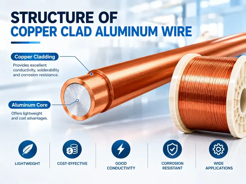
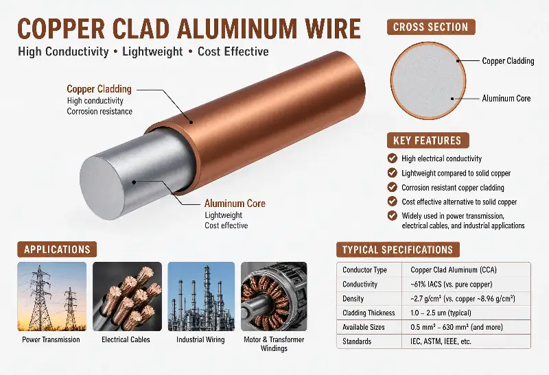
Copper-clad aluminum wire (CCA or CCAW) is a bimetallic composite conductor. In cross-section, it consists of a solid aluminum core surrounded by a uniformly wrapped layer of metallurgically bonded copper. This seemingly simple structure—an aluminum core with a copper sheath—is actually the result of a sophisticated engineering process involving material composition, interface metallurgy, and volume fraction balance.
Understanding the structure of CCA wire is crucial for engineers in selection, QC sampling, and application adaptation. This article starts with conductor fundamentals and analyzes the composition, manufacturing process, standard classification, enameled variants (ECCA), and structural defects and detection methods of CCA wire layer by layer.
Overview of CCA Lines and Basic Bimetallic Structures
CCA wire is not an alloy. It is a composite material—an aluminum core and a copper cladding are bonded together in a metallurgical manner, but the two metals maintain their respective chemical compositions at the interface and do not diffuse into each other to form a new phase.
CCA line definition and origin of bimetallic conductors
Copper-clad aluminum wire (CCAW/CCA) is a bimetallic electrical conductor consisting of an aluminum core and an outer copper cladding. This design is based on the skin effect—high-frequency alternating current (AC) tends to flow through the surface of the conductor. By placing the more conductive copper on the outer layer and the cheaper, lighter aluminum on the inner layer, cost and weight can be significantly reduced while retaining most of the conductivity.
Aluminum cores typically comprise 73%–90% of the total cross-sectional area of the conductor. For the same weight, CCA wires are 2.5–2.6 times longer than pure copper wires; diameter specifications cover Ø0.04–Ø5.15 mm.
Aluminum core material selection: 1350 aluminum alloy vs other aluminum alloys
Industrial-grade CCA wires primarily use 1350 aluminum alloy (also written as AA1350 or 1350-O) as the core material. 1350 is electrical-grade aluminum with a purity ≥99.5%, iron content controlled below 0.4%, and silicon content ≤0.10%. The goal of this composition design is to maximize conductivity (IACS ≥61%) and control mechanical property stability.
The 1350-O annealed state has a tensile strength of 70–95 MPa and an elongation of 25–30%; the 1350-H19 hard state has a tensile strength of up to 160 MPa and an elongation of only 1–3%. Therefore, the soft CCA wire (Class 10A/15A) core material is in the annealed state, while the hard CCA wire (Class 10H/15H) core material is in the strain-hardened state.
Copper cladding: C11000/C10200 oxygen-free copper material selection
The copper layer material is typically C11000 electrolytic tough pitch copper (ETP, oxygen content 0.02–0.04%) or C10200 oxygen-free copper (OFC, oxygen content ≤0.001%). Both are high-purity copper (≥99.9%), but oxygen-free copper offers more stable conductivity and heat resistance in high-frequency applications, but is also more expensive.
C11000 and C10200 are basically interchangeable in CCA cable applications. The difference is: when CCA cables are used in high-temperature environments above 200°C or in vacuum environments, oxygen-free copper can avoid the risk of hydrogen embrittlement; for ordinary audio/home appliance applications, C11000 is sufficient.
Metallurgical bonding process and 3 major manufacturing methods
The key to CCA wire lies in the copper-aluminum interface—it must be a metallurgical bond, not just a simple mechanical coating. If you simply wrap a copper tube around an aluminum rod, the copper layer will crack and peel off when bent.
Co-extrusion: the mainstream process for CCA lines
Co-extrusion (also known as co-temperature extrusion) is currently the most mainstream process for manufacturing CCA lines. The process flow is as follows: first, an aluminum rod is inserted into a copper tube (or a copper strip is rolled into a tube), and then aluminum and copper are extruded simultaneously through a die. During the extrusion process, copper and aluminum undergo plastic deformation under high temperature and pressure, and the interfacial atoms diffuse into each other to form a metallurgical bond layer (approximately 0.5–5 μm thick).
The advantages of isothermal extrusion are high interfacial bonding strength, continuous production capability, and suitability for manufacturing small to medium gauge (Ø0.5 – Ø3.0 mm) fine wire and enameled wire blanks. The disadvantages are that larger gauge wires (>Ø3 mm) require a higher extrusion ratio, resulting in higher equipment investment.
Clad welding: Applications in large diameter wires
Clad welding (also known as cladding + drawing) is suitable for manufacturing large-gauge CCA wires or long-length cable cores. The process involves continuously wrapping copper strips around an aluminum core, then fusing the edges of the copper strips together using high-frequency welding or TIG welding to form a complete copper layer. After welding, the entire assembly undergoes tensile annealing, ultimately resulting in a copper-aluminum metallurgical composite CCA wire.
The advantages of this method are high production capacity, single-wire lengths of up to tens of kilometers, and the ability to manufacture large-diameter conductors with a cross-sectional area of 25 mm² or more. The disadvantage is that uneven copper layer formation may occur in the soldering area, requiring subsequent online eddy current testing for removal.
Hydrostatic extrusion: High density applications
Hydrostatic extrusion uses a high-pressure liquid (usually castor oil) as the pressure medium to extrude coated aluminum-copper billets through a die. The liquid pressure is transmitted uniformly, avoiding the uneven friction problems in traditional extrusion, resulting in a copper-aluminum interface with extremely high density and almost no voids.
This process is suitable for manufacturing high-density CCA lines for aerospace, military, and high-end medical devices, but the cost is 3–5 times that of isothermal extrusion, and it is rarely seen in the civilian market.
Detailed Explanation of ASTM B-566 Standard and 4 Class Ratings
ASTM B-566 is the most commonly used standard for CCA wire in North America. This standard divides CCA wire into four grades: Class 10A/15A (annealed) and Class 10H/15H (hard).
Class 10A vs Class 15A (annealed state, A = Annealed)
Both Class 10A and Class 15A are annealed (O temper), differing only in the copper volume fraction:
- Class 10A: Copper occupies 10% of the volume, aluminum core 90%. IACS conductivity is approximately 63–65%.
- Class 15A: Copper occupies 15% of the volume, aluminum core 85%. IACS conductivity is approximately 65–68%.
Annealed CCA wire is soft and has a high elongation (≥25%), making it suitable for applications that require repeated bending, such as audio voice coils, headphone cables, and small transformer leads.
Class 10H vs Class 15H (hard state, H=Hard)
Both Class 10H and Class 15H are in the hard state (H19 temper), differing only in the copper volume fraction:
- Class 10H: 10% copper, neither copper nor aluminum is annealed. High tensile strength (≥130 MPa), but elongation is only 2–4%.
- Class 15H: 15% copper, performance between Class 10H and the annealed range.
Rigid CCA wires are often used in structural applications such as coil bobbin supports, busbars, and transposed conductors (CTCs), where the wire needs to maintain its shape and not spring back.
Comparison of volume fraction and conductivity in Class 4
The following table summarizes the key structural parameters for ASTM B-566 Class 4:
| Class Level | Copper layer volume fraction | Copper layer thickness (mm, 1.0mm total diameter) | IACS conductivity (%) | Tensile strength (MPa) | Elongation (%) | Typical applications |
|---|---|---|---|---|---|---|
| Class 10A | 10% | 0.05 | 63–65 | 70–95 | ≥25 | Audio/small transformer leads |
| Class 15A | 15% | 0.08 | 65–68 | 80–110 | ≥20 | Enamelled wire blanks/home appliances |
| Class 10H | 10% | 0.05 | 63–65 | ≥130 | 2–4 | Coil frame/transposed wire |
| Class 15H | 15% | 0.08 | 65–68 | 140–170 | 3–5 | Busbar/Structural Components |
Note that the numbers in Class 10 / Class 15 are not copper layer thicknesses, but rather volume fractions—this differs from the naming convention of the commonly used domestic standard SJ/T 11223-2000.
Engineering significance of copper layer volume fraction (10/15/20/27%)
The copper volume fraction is the most critical structural parameter of CCA wire. It directly determines conductivity, mechanical properties, cost, and weight.
Definition of volume fraction and geometric proportion
The volume fraction is defined as the volume of the copper layer divided by the total volume of the conductor. For round wire, assuming the aluminum core radius r₁ and the outer radius of the copper layer r₂, the copper layer volume fraction Vf = 1 − (r₁/r₂)². For example, for Class 15A wire, r₁/r₂ = √(1 − 0.15) = 0.922, and the copper layer thickness is approximately r₂ − r₁ = 0.078 × r₂.
For a CCA line with an overall diameter of Ø1.0 mm, the Class 15A copper layer thickness is approximately 0.04 mm (one side). This thickness is sufficient for high-frequency currents—the skin depth of copper is approximately 0.066 mm at 1 MHz, and the 0.04 mm copper layer of Class 15A can carry more than 60% of the surface current.
Effect of volume fraction on conductivity (IACS)
Theoretically, the IACS conductivity of a CCA wire = copper layer IACS × copper volume fraction + aluminum core IACS × aluminum volume fraction. Pure copper IACS = 100%, pure aluminum IACS = 61%.
Substituting into Class 10A: 100% × 10% + 61% × 90% = 10% + 54.9% = 64.9%, which matches the actual value of 63–65%. Class 15A: 100% × 15% + 61% × 85% = 15% + 51.85% = 66.85%, which is actually 65–68%.
If the copper layer is further increased to 27%, the IACS can reach 70.3%—this is the origin of the 70% IACS claimed by some high-end CCA lines (such as PCCC, pure copper-clad aluminum).
Effect of volume fraction on high-frequency skin resistance
DC resistance is only related to the volume fraction. However, at high frequencies (>100 kHz), the current concentrates in the copper layer, and the aluminum core hardly plays a conductive role—at this time, the effective resistance approaches that of pure copper wire (the higher the volume fraction of the copper layer, the closer the high-frequency resistance is to that of pure copper).
For example, at 1 MHz, the AC resistance of Class 15A is approximately 1.05–1.10 times that of pure copper wire, while the AC resistance of Class 10A is approximately 1.15–1.25 times that of pure copper wire. This is why high-frequency applications (such as wireless charging and RF coaxial cables) tend to use Class 15A instead of Class 10A—the extra 5% copper layer significantly reduces high-frequency losses.
Enamelled CCA wire (ECCA): Insulation coating structure
Enameled Copper Clad Aluminum Wire (ECCA) is a standard enameled wire variant with an insulating enamel coating applied to the outside of the CCA conductor. It inherits the cost/weight advantages of CCA and the insulation properties of enameled wire.
ECCA definition and three-layer structure (copper layer + enamel film)
The structure of ECCA can be understood as three concentric circles:
1. Aluminum core: 1350-O aluminum alloy, providing mechanical support and most of the volume.
2. Copper cladding: C11000 or C10200 oxygen-free copper, providing conductivity and oxidation resistance.
3. Enamel coating: Polyester/polyimide/polyimide and other polymer coatings, providing insulation.
According to the IEC 60317 standard, paint film thickness is divided into three grades: Grade 1 (thin), Grade 2 (standard), and Grade 3 (thick). For example, the diameter increase of Grade 2 paint film for Ø1.0 mm ECCA lines is approximately 0.06–0.08 mm.
Coating material selection: PEW/UEW/EIW/AIW/PIW
Different coating materials are used for different applications:
- UEW (Polyurethane, QZ): Good solderability, 155°C rating, suitable for high-frequency coils and relays.
- PEW (Polyester, QA): 180°C rating, balances heat resistance and cost, preferred for household appliance motors.
- EIW (Polyesterimide, QZY): 200°C rating, mainstream for motor windings.
- AIW (Polyamide-Imide, QZY/XY): 220°C rating, used for outer layer composites, improving heat and refrigerant resistance.
- PIW (Polyimide, QY): 240°C rating, used in aerospace/military/deep well motors.
ECCA lines often use a dual coating structure—an inner EIW layer (with strong adhesion to the copper layer) + an outer AIW layer (heat and chemical resistant), resulting in optimal overall performance.
ECCA Standards Framework: IEC 60317/NEMA MW 1000
The standard system for ECCA wire shares the same set of standards as enameled copper wire and enameled aluminum wire:
- IEC 60317 Series: International Electrotechnical Commission standards, corresponding volumes for ECCA: IEC 60317-0-3 / IEC 60317-13, etc.
- NEMA MW 1000: North American Electrotechnical Commission, MW 35 / MW 73 / MW 79, etc.
- JIS C 3202: Japanese Industrial Standard
- ASTM B 566-93: American Society for Testing and Materials (applicable to bare CCA conductors)
- GB/T 6109: Chinese National Standard
This means that ECCA wire is fully compatible with enameled copper and enameled aluminum wires at the standard level—it can directly replace existing winding designs, only requiring attention to conductor cross-sectional area conversion.
Physical property comparison: CCA wire vs. pure copper wire vs. pure aluminum wire
The most direct way to understand the advantages and disadvantages of CCA wire is to compare it with pure copper wire and pure aluminum wire.
The three fundamental physical properties of materials (density/electrical conductivity/thermal conductivity)
| Material | Density (g/cm³) | IACS conductivity (%) | Resistivity (μΩ·cm) | Thermal conductivity (W/m·K) | Price ratio of the same diameter | Length ratio of the same weight |
|---|---|---|---|---|---|---|
| Pure copper C11000 | 8.94 | 100 | 1.724 | 401 | 1.0× | 1.0× |
| CCA Class 15A | 3.63–4.10 | 65–68 | 2.40–2.60 | 190–250 | 0.6× | 2.5–2.6× |
| Pure aluminum 1350-O | 2.70 | 61 | 2.826 | 237 | 0.3× | 3.3× |
CCA linear density falls between that of pure copper and pure aluminum, depending on the volume fraction of the copper layer. Class 15A has a density of approximately 3.7 g/cm³—meaning it is 2.5–2.6 times longer than pure copper wire of the same weight.
Comparison of mechanical properties (tensile strength/elongation/hardness)
Tensile strength (annealed state): Pure copper C11000-O approx. 220 MPa > Class 15A approx. 80–110 MPa > Pure aluminum 1350-O approx. 70–95 MPa.
Elongation (annealed state): Pure copper 35–45% > Class 15A 20–25% > Pure aluminum 25–30%. Note that the elongation of CCA wire is limited by the copper-aluminum interface strength and is generally lower than that of pure copper.
Hardness (HV): Pure copper in the O state is about 50 HV, pure aluminum in the O state is about 25 HV, and CCA Class 15A annealed state is about 35–45 HV.
Economic comparison (cost per meter/weight/total cost)
Cost for the same diameter: CCA is approximately 30–50% less than pure copper. Class 15A wire with a diameter of 1.0 mm has a unit price of approximately 60–70% of that of pure copper wire.
Cost per unit weight: CCA < pure copper by approximately 60–70%. 1 ton of pure copper wire corresponds to 2.6 tons of CCA wire (of the same diameter).
Overall economics: For low- to mid-range home appliances, audio equipment, and low-voltage winding applications, CCA wires can save 25–40% on material costs; however, in high-frequency/high-power scenarios, the conductivity and heat dissipation advantages of pure copper cannot be completely replaced by CCA.
Structural Defects and Quality Inspection Methods
The complex structure of CCA lines implies unique defect patterns. Understanding these defects and their detection methods is crucial for quality control.
Typical structural defects: delamination/uniform copper layer/interface voids
Common structural defects in CCA lines include:
1. Delamination: The copper layer separates from the aluminum core during bending. This is the most serious defect, leading to a sharp drop in conductivity and mechanical failure. Causes include insufficient extrusion temperature/pressure or interface contamination.
2. Uneven Copper Layer Thickness: The copper layer thickness deviation on the cross-section is >20%. This is usually due to wear of the extrusion die or fluctuations in the cladding welding speed.
3. Interface Voids: Air bubbles or unfilled areas exist at the copper-aluminum interface. Visible under a high-magnification microscope (×100), these become stress concentration points.
4. Copper Layer Cracks: Cracks appear on the copper layer surface of hardened wires (H grade) when the bending radius is too small. IEC 60317 requires that the wire still pass the winding test after enameling.
5. Eccentricity: The aluminum core deviates from its geometric center, resulting in uneven copper layer thickness on one side, causing uneven current density.
5 Structural Defects vs. Corresponding Inspection Methods
The following table summarizes the engineering comparison of the 5 major structural defects of CCA wire and recommended inspection methods:
| Defect type | Defect characteristic | Recommended inspection method | Detection sensitivity | Engineering acceptance threshold | Repair/scrap decision |
|---|---|---|---|---|---|
| Delamination | Separation of Cu-Al interface during bending | Mandrel winding (1×) + SEM | High | No visible separation after 10 turns | Scrap |
| Uneven copper layer thickness | Cross-section thickness deviation >20% | Eddy current (inline) + Metallographic | Medium-High | Deviation ≤±15% | Rework defective batches |
| Interface voids | Air bubbles / unfilled areas at Cu-Al interface | Metallographic microscope (×100) + SEM | High | Void ratio ≤2% | Scrap severe cases |
| Copper layer cracks (H state) | Caused by too-small bending radius | Mandrel winding + IEC 60317 enamel test | Medium | No visible cracks | Scrap defective batches |
| Eccentricity | Aluminum core deviates from geometric center | Metallographic section + Eddy current phase analysis | High | Eccentricity ≤10% | Scrap severe cases |
Microscopic inspection: SEM/TEM/metallographic sections
Microscopic inspection is used to assess interfacial bonding quality and defect size:
- Metallographic cross-section: The cross-section of the CCA line is polished, etched, and observed using an optical microscope. Copper layer thickness, aluminum core location, and interfacial voids can be directly measured.
- SEM (Scanning Electron Microscopy): Magnified 1000–10000x, observes the interfacial microstructure and diffusion layer thickness (typically 1–5 μm).
- TEM (Transmission Electron Microscopy): Magnified 50000+x, identifies intermetallic compounds (such as CuAl₂ and Cu₉Al₄). Excessive thickness of these compounds can lead to interfacial embrittlement.
- EDS (Energy Dispersive Spectroscopy): Combined with SEM, quantifies the copper-aluminum concentration gradient at the interface.
Macroscopic testing: Eddy current/resistance/peel strength testing
Macroscopic inspection is a rapid method for 100% random sampling on the production line:
- Eddy Current Test: Determines the uniformity of copper layer thickness by detecting changes in eddy currents induced by a coil. Speeds can reach 2000 m/min.
- Resistance Test: Excessive resistance per unit length indicates insufficient copper layer or interface defects. For Class 15A Ø1.0 mm wire, resistance should be ≤28 mΩ/m.
- Peel Strength Test: The force required to peel the copper layer from the aluminum core (typically ≥5 N/mm). Not mandatory under IEC 60317, but may be specified by UL and military customers.
- Mandrel Winding Test: The wire is tightly wound 10 turns onto a 1× diameter mandrel; no delamination or cracks indicate acceptance.
Application scenarios and structural selection decisions
The structural selection of CCA lines ultimately serves the application. Different scenarios have significantly different requirements for copper layer volume fraction, annealed/hardened state, and coating grade.
Structural requirements for high-frequency applications (RF/wireless charging/coaxial cable)
For high-frequency applications (>100 kHz), Class 15A enameled ECCA wire is the preferred choice, with a Litz structure (multi-strand insulated fine wire twisted together).
Reason: The skin effect concentrates current in the copper layer, and Class 15A has 10–15% lower high-frequency losses than Class 10A. Annealing ensures a small bending radius, allowing for the creation of fine coils. Wireless charging transmitter coils (100–200 kHz) typically use Ø0.05–0.10 mm × 200 strands of ECCA Litz wire.
Structural requirements for high-current applications (power/transformer/transposed conductors)
For high-current applications (hundreds to thousands of amperes), Class 10H or 15H hard bare CCA wires are preferred.
Reason: Hardened CCA wire has high tensile strength and can withstand coil winding tension and short-circuit electrodynamic forces. Replacing pure copper transposing wire with hardened CCA wire for Continuously Transposed Conductor (CTC) can reduce transformer weight by 20–30%. However, attention should be paid to the need for correspondingly improved heat dissipation design—CCA has lower thermal conductivity than pure copper, resulting in a 15–20°C higher temperature rise under the same current.
The structural balance point of audio/home appliance CCA cables
For applications requiring medium performance, such as audio voice coils, home appliance motors, and lighting ballasts, Class 10A enameled ECCA wire offers the best balance.
Reason: Audio voice coils operate at lower frequencies (20 Hz–20 kHz), resulting in less skin effect; Class 10A is sufficient. For household appliance motors (air conditioner/refrigerator compressors), cost and weight are critical; Class 10A is 8–12% cheaper than Class 15A. Furthermore, the annealed state facilitates automated winding.
Project Summary: Key Considerations for CCA Line Structural Selection
From a structural integrity perspective, the key to the success of CCA lines is not the highest percentage of any particular copper layer, but rather the reliability of the interfacial bonding. Any sign of copper-aluminum separation means the conductor is unusable—this applies to both Class 10A and Class 15H. Therefore, when selecting a CCA line, it is crucial to consider the manufacturing process (isothermal extrusion is more reliable than overcoating bonding) and the supplier’s SEM/TEM test reports.
From an application perspective, Class 15A is chosen for high frequencies (sacrificing cost for lower loss), Class 10H or 15H is chosen for high current (sacrificing flexibility for mechanical strength), and Class 10A is chosen for general household appliances/audio equipment (a balance point). These three scenarios correspond to three different structures – performance trade-offs; there is no single “best-in-class” CCA cable structure.
Looking at future development trends, with the continued rise in copper prices (LME $8000–11000/ton) and global demand for lightweighting (new energy vehicles, aviation, 5G base stations), the application boundaries of CCA and ECCA enameled wires are expanding. Some mid-to-high-end applications that were originally exclusive to pure copper (such as electric vehicle components, energy storage inductors, and high-end audio) are beginning to evaluate CCA alternatives. In terms of manufacturing processes, continuous extrusion and laser-assisted bonding are making it possible to mass-produce CCA wires with higher copper fractions, such as Class 20 and Class 27.