


Introduction
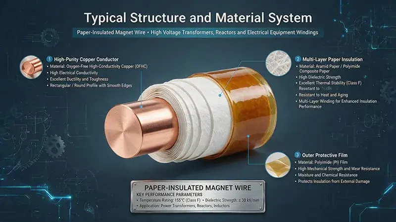
Paper-covered wire is a paper-insulated winding conductor produced by helically wrapping one or more layers of electrical-grade cellulose paper—typically 0.05–0.13 mm thick—around a bare or enameled copper or aluminum round conductor. Common paper types include kraft paper, crepe paper, thermally upgraded kraft paper (TUK), and thermally upgraded crepe paper (TUCP), all conforming to IEC 60851, IEC 60317, and ASTM D202. This conductor type is extensively employed in oil-immersed power transformers, distribution transformers, traction transformers, HVDC converter transformers, furnace transformers, and rectifier transformers.
Compared with enameled round wire, fiberglass-covered wire, and enameled rectangular wire, paper-covered wire delivers distinct advantages in oil-immersed applications: superior oil-impregnation capability; low dielectric loss; high dielectric strength following oil impregnation; excellent thermal aging resistance—up to Class A (105 °C) and even Class E (120 °C); mechanical flexibility compatible with high-speed automatic winding equipment; and cost-effective, readily available raw materials.
With the rapid advancement of UHV AC/DC transmission systems, integration of new energy sources into the grid, and development of high-power industrial transformers, paper-covered wire remains a critical enabling material in modern transformer systems. This paper provides a systematic review of paper-covered wire in relation to transformer system performance, with focused analysis on its impact on dielectric performance, thermal performance, mechanical performance, electrical efficiency, reliability, service life, and overall transformer system behavior.
Material Systems and Conductor Configurations
Paper Materials and Classification
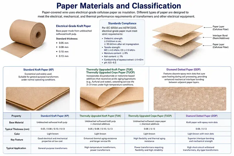
The base paper used in paper-covered wire is electrical-grade cellulose paper manufactured from unbleached softwood kraft pulp, with standard thicknesses of 0.05 mm, 0.08 mm, 0.10 mm, or 0.13 mm. Per IEC 60554 and ASTM D202, electrical-grade paper must meet stringent requirements for dielectric strength (≥8 kV/mm in air; ≥30 kV/mm after oil impregnation), tensile strength (machine direction ≥4.5 kN/m; cross direction ≥2.0 kN/m), moisture content (≤8%), ash content (≤1%), conductivity of aqueous extract (≤4 mS/m), and pH (6.5–8.5). Thermally upgraded kraft paper (TUK) and thermally upgraded crepe paper (TUCP) incorporate chemical additives—typically dicyandiamide or melamine-based compounds—that neutralize acidic aging byproducts (e.g., furfural and water), thereby extending service life by a factor of 2–3 compared to standard kraft paper under elevated-temperature operating conditions. Diamond Dotted Paper (DDP) features discrete epoxy resin dots that cure upon heating during transformer coil processing, delivering enhanced mechanical interlayer bonding between adjacent paper layers.
Conductor Materials and Cross-Sections
Paper-covered wire employs bare or pre-enameled copper conductors compliant with IEC 60317, ASTM B49, and GB/T 3953, with standard nominal diameters ranging from 0.50 mm to 5.00 mm in increments specified in IEC 60317-0-1. Round conductors with diameters of 1.00–2.50 mm are most widely used in low-voltage distribution transformers and auxiliary windings of traction transformers; larger-diameter conductors (3.00–5.00 mm) are applied in high-current industrial and furnace transformers. Aluminum conductors—typically alloy 1350-O or 1370-O per ASTM B230/B233—may also be employed where weight reduction is critical (e.g., mobile substations, dry-type distribution transformers); however, copper remains the predominant choice due to its higher electrical conductivity, superior solderability, and greater resistance to creep deformation.
Wrapping Configurations and Insulation Build-up
Paper wrapping configurations commonly employ 1-, 2-, 3-, or 4-layer helical wraps, with overlap ratios ranging from 30% to 60%. The most frequently adopted configuration is two layers with 50% overlap, yielding an effective insulation thickness of approximately 0.10–0.13 mm. Crepe paper, owing to its inherent stretchability, conforms effectively to irregular conductor surfaces and provides superior mechanical cushioning—particularly beneficial in winding corners and lead-out regions. Multi-layer wrapping schemes may combine different paper types—for example, inner kraft paper for dielectric integrity and outer crepe paper for mechanical protection. In high-voltage windings (10 kV class and above), paper-covered wire is often integrated with interlayer oil-duct spacers or Diamond Dotted Paper (DDP) to improve partial discharge inception voltage (PDIV).
Influence on Dielectric Performance
Dielectric Strength and Partial Discharge Behavior
The dielectric strength of paper-covered wire is primarily determined by the oil-impregnated paper insulation, rather than by dry paper alone. Dry paper exhibits a dielectric strength of approximately 8–10 kV/mm, whereas oil-impregnated paper achieves 30–60 kV/mm—a 4–6× improvement resulting from the elimination of internal air voids and their replacement with high-dielectric-strength mineral oil or ester fluid. The intrinsic dielectric strength follows Weibull statistics, with a characteristic breakdown field of approximately 50–70 kV/mm for high-quality kraft paper following proper vacuum oil impregnation. When measured in accordance with IEC 60270, the partial discharge inception voltage (PDIV) of paper-covered wire windings typically ranges from 1.5–2.5 kV (rms) for a two-layer kraft paper construction, increasing to 3.0–4.5 kV for a four-layer configuration. The partial discharge extinction voltage (PDEV) is generally 80–90% of the PDIV. In contrast, enameled round wire windings of comparable insulation thickness exhibit PDIV values that are 20–40% lower, owing to the absence of oil impregnation capability in the solid enamel insulation.
Dielectric Loss and tanδ Behavior
The dielectric loss factor (tanδ) of paper-covered wire after oil impregnation is approximately 0.002–0.004 at 50 Hz and 25 °C, dominated by the loss characteristics of the oil-impregnated paper. Moisture content has a pronounced effect on tanδ: at 0.5% moisture by weight, tanδ may increase by 50–100%, while at 1.0% moisture, tanδ may exceed 0.01. Consequently, vacuum drying of transformer windings prior to oil impregnation is critical; the target moisture content must be maintained below 0.3%, as specified in IEC 60076-1. The temperature dependence of tanδ follows the Curie-von Schweidler relation, with peak dielectric dissipation occurring near 60–80 °C—where moisture-related dipole relaxation overlaps with conduction losses. Aged paper insulation (after 20+ years of service) exhibits a progressive increase in tanδ due to the accumulation of acidic aging by-products—predominantly acetic and formic acids—with tanδ values approaching 0.01 or higher indicating end-of-life conditions.
Permittivity and Voltage Distribution
The relative permittivity (εr) of oil-impregnated paper insulation is approximately 3.5–4.5 at 50 Hz, lying between that of mineral oil (εr ≈ 2.2) and solid epoxy (εr ≈ 4.0–5.0). This moderate εr value contributes to a more uniform voltage distribution along the winding insulation path compared with enameled wire systems, where permittivity discontinuities arise from the combination of enamel (εr ≈ 3.0–4.0) and air gaps (εr ≈ 1.0), leading to electric field concentration. The integrated oil-paper insulation system maintains stable permittivity over a temperature range of 20–120 °C (typically exhibiting <15% variation), thereby ensuring consistent voltage distribution under varying load and thermal conditions.
Influence on Thermal Performance
Thermal Conductivity and Heat Dissipation
Oil-impregnated paper insulation exhibits a thermal conductivity of approximately 0.15–0.25 W/m·K—slightly higher than that of dry paper (0.10–0.15 W/m·K) but significantly lower than that of enameled wire insulation (e.g., epoxy-impregnated, 0.20–0.30 W/m·K). However, when paper-covered wire windings are immersed in transformer oil, the surrounding oil (thermal conductivity ≈ 0.13 W/m·K) provides effective convective heat transfer that complements conduction through the paper layer. The overall heat transfer coefficient (*h*) of oil-submerged paper-covered wire windings is approximately 80–150 W/m²·K under natural oil circulation (ONAN) and 200–350 W/m²·K under forced oil circulation (OFAF). In contrast, dry-type transformer windings using enameled wire with air cooling typically exhibit *h* values of 10–30 W/m²·K—roughly one order of magnitude lower—thereby limiting their thermal performance.
Temperature Class and Aging Behavior
Paper-covered wire is rated for Class A (105 °C) insulation systems under continuous operation, corresponding to conventional kraft paper with standard aging characteristics. Thermally upgraded kraft paper (TUK) extends the rating to Class E (120 °C), with service life governed by the Montsinger rule (each 8–10 °C increase in operating temperature halves insulation life). Per IEC 60076-7 and IEEE C57.91, the hot-spot temperature rise for Class A oil-immersed transformers is limited to 78 K above ambient, while the average winding temperature rise is limited to 65 K. Standard kraft paper operated continuously at 95 °C yields an estimated service life of approximately 20–25 years; at 105 °C, life decreases to 12–18 years; and at 115 °C, it further declines to 5–8 years. TUK and thermally upgraded crepe paper (TUCP) effectively shift the aging curve, enabling 30–40+ years of service at 110 °C continuous operation.
Thermal Cycling and Mechanical Integrity
Paper-covered wire windings experience thermal cycling during transformer load variations, with daily load fluctuations and seasonal ambient temperature changes inducing cyclic thermal stress. The mismatch in coefficients of thermal expansion (CTE) between paper insulation (CTE ≈ 30–40 × 10⁻⁶/K along the fiber direction; 60–80 × 10⁻⁶/K transverse to the fiber) and the copper conductor (CTE ≈ 17 × 10⁻⁶/K) generates interfacial shear stress. Over thousands of thermal cycles, this may result in paper delamination or loosening at the conductor–paper interface, potentially creating voids that initiate partial discharge. Arrhenius kinetics of cellulose aging (activation energy ≈ 110 kJ/mol for standard kraft paper; ≈ 130 kJ/mol for TUK) predicts accelerated degradation at elevated temperatures, with the degree of polymerization (DP) of cellulose decreasing from initial values of 1000–1200 to end-of-life values of 200–250 over decades of operation.
Influence on Mechanical Performance
Short-Circuit Strength and Winding Stability
During external short-circuit events, transformer windings are subjected to extremely high electromagnetic forces—proportional to the square of the fault current. In windings employing paper-covered wire, radial and axial forces are distributed across multiple parallel conductors; each conductor experiences compressive or tensile stresses along its length. Although the paper insulation layer serves primarily as a dielectric barrier, it also contributes to mechanical damping by absorbing vibrational energy through its viscoelastic behavior. Compared with enameled round wire of identical diameter, paper-covered wire exhibits a radial compressive elastic modulus approximately 15–25% higher, attributable to the constraining effect of the paper layer acting as a reinforcing band. However, the paper insulation is more vulnerable to mechanical damage—such as cracking or delamination—during sharp bending or impact in winding operations, necessitating strict handling protocols and precise tension control.
Vibration Damping and Acoustic Performance
Transformer noise originates predominantly from magnetostriction-induced core vibrations transmitted to the windings and tank walls. Winding mechanical properties significantly influence this acoustic emission. Windings made with paper-covered wire—featuring compliant paper layers between adjacent conductors—exhibit mechanical damping approximately 30–50% greater than geometrically equivalent enameled wire windings. This enhanced damping attenuates the amplitude of mechanical resonance peaks at 100 Hz, 200 Hz, 300 Hz, and higher harmonics, resulting in a reduction of the A-weighted sound pressure level (SPL) by 1–3 dB(A) relative to enameled wire windings in identical transformer designs. In noise-sensitive applications—such as urban substations adjacent to residential areas or indoor transformer installations—this 1–3 dB(A) improvement can be decisive. Additionally, paper-covered wire facilitates more uniform distribution of winding tension during manufacturing, further contributing to reduced in-service vibration amplitudes.
Winding Process Compatibility
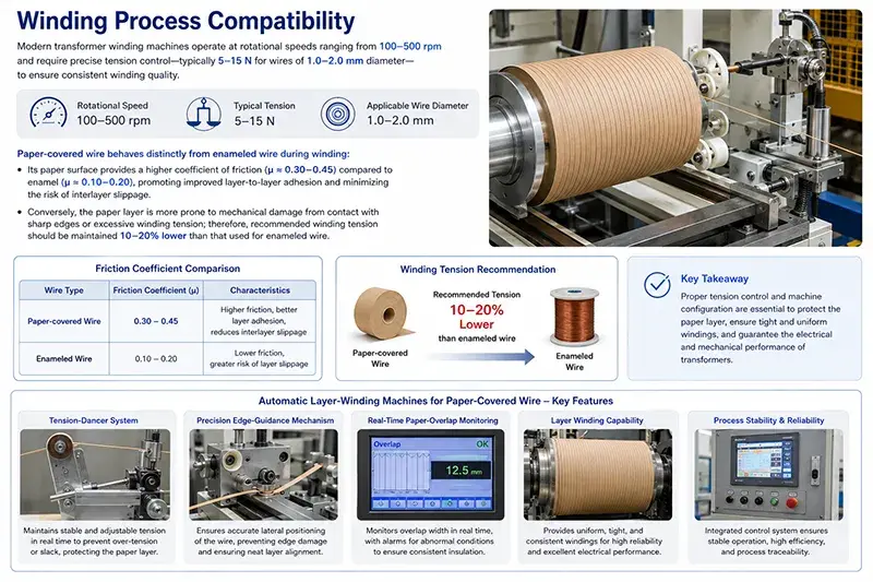
Modern transformer winding machines operate at rotational speeds ranging from 100–500 rpm and require precise tension control—typically 5–15 N for wires of 1.0–2.0 mm diameter—to ensure consistent winding quality. Paper-covered wire behaves distinctly from enameled wire during winding: its paper surface provides a higher coefficient of friction (μ ≈ 0.30–0.45) compared to enamel (μ ≈ 0.10–0.20), promoting improved layer-to-layer adhesion and minimizing the risk of interlayer slippage. Conversely, the paper layer is more prone to mechanical damage from contact with sharp edges or excessive winding tension; therefore, recommended winding tension should be maintained 10–20% lower than that used for enameled wire. Automatic layer-winding machines specifically engineered for paper-covered wire incorporate dedicated features—including tension-dancer systems, precision edge-guidance mechanisms, and real-time paper-overlap monitoring—to guarantee process reliability and winding integrity.
Influence on Electrical Efficiency
Load Loss and Resistive Behavior
Paper-covered wire employs bare copper or aluminum conductors, with the insulation paper contributing negligibly to current conduction; thus, the DC resistance (DCR) is determined solely by conductor geometry and resistivity, in accordance with IEC 60028. The paper insulation provides no conduction path and introduces only minimal additional loss at power frequencies. At 50 Hz, the AC resistance (ACR) of paper-covered wire windings is typically 1.05–1.15 × DCR due to the skin effect; this ratio rises to 1.2–1.5 × DCR at 1 kHz and further increases to 2.5–4.0 × DCR at 10 kHz. These ACR/DCR ratios are slightly lower than those observed for solid conductors of equivalent diameter, owing to geometric constraints imposed by the paper layer on current redistribution across the conductor cross-section. In comparison with Litz wire—commonly employed in high-frequency winding applications—paper-covered wire exhibits significantly higher ACR above 1 kHz, thereby restricting its application to power-frequency (50/60 Hz) and low-frequency audio-range uses.
Eddy Current Loss and Proximity Effect
In multi-layer paper-covered wire windings, eddy currents induced by leakage flux generate supplementary losses that scale approximately with the square of the layer index relative to the source of the leakage field. For paper-covered wire with conductor diameters in the range of 1.5–2.5 mm, proximity-effect losses at 50 Hz typically amount to 2–5% of the fundamental I²R loss in high-current windings, increasing to 8–15% at 1 kHz. Although the paper insulation offers marginal eddy-current isolation between adjacent conductors, it falls considerably short of the performance achieved by purpose-designed proximity-effect insulation used in Litz wire. Consequently, paper-covered wire is generally unsuitable for industrial frequency converters operating in the 5–20 kHz range; enameled wire with rectangular cross-section or Litz wire is instead preferred.
No-Load Loss and Magnetic Considerations
Paper-covered wire windings have no direct impact on no-load loss (i.e., core loss), which is governed exclusively by the magnetic properties and geometry of the core material—typically grain-oriented silicon steel or amorphous metal ribbon. However, the dimensional accuracy and geometric consistency of paper-covered wire windings influence the distribution of leakage flux, thereby affecting stray losses in transformer tank walls, structural components, and inter-winding capacitance. High-precision paper-covered wire windings—characterized by uniform layer winding and tight dimensional control—can reduce stray losses by 5–10% relative to poorly executed windings. This improvement translates into an overall efficiency gain of 0.05–0.15 percentage points in large power transformers.
Influence on Reliability and Service Life
Aging Mechanisms and Lifespan Modeling
Aging of paper insulation in oil-immersed transformers proceeds via three principal mechanisms: (i) hydrolytic degradation, wherein water molecules cleave the β-1,4-glycosidic bonds of cellulose; (ii) oxidative degradation, wherein oxygen attacks cellulose chains in the presence of catalytic metal impurities (e.g., copper and iron); and (iii) thermal degradation, wherein elevated temperature accelerates bond scission. The degree of polymerization (DP) of cellulose—measured per ASTM D4243 and IEC 60450—typically declines from an initial value of 1000–1200 to an end-of-life range of 200–250 over decades of service. Furfural concentration in transformer oil—determined per ASTM D5837 and IEC 61198—serves as a widely accepted non-invasive indicator of insulation aging: concentrations below 0.1 mg/L indicate healthy insulation; values between 0.5 and 2.0 mg/L reflect moderate aging; and levels exceeding 4 mg/L signal advanced degradation and imminent end-of-life. End-of-life prediction is commonly based on the Arrhenius model with an activation energy of 110–130 kJ/mol, yielding predictions with approximately ±20% accuracy.
Moisture Management and Bubble Formation
Moisture content in paper-covered wire windings constitutes a critical reliability factor, directly accelerating insulation aging and reducing dielectric strength. Modern transformer manufacturing requires vacuum drying to reduce the moisture content of cellulose paper to less than 0.3% by weight prior to oil impregnation. During service, moisture may ingress from ambient air through breathers or gasket interfaces, gradually increasing paper moisture content to 1–3% over years—particularly in units equipped with free-breathing conservators. At sub-zero temperatures (< 0 °C), moisture may crystallize into ice, exhibiting higher dielectric losses; during rapid load increases, moisture migration toward thermal hot spots can locally saturate the paper, creating a risk of bubble formation when local temperatures exceed 100 °C and local moisture content surpasses ~2%. Online moisture monitoring—using capacitive sensors—and Duval triangle analysis of dissolved gas analysis (DGA) data support timely diagnostic intervention.
Partial Discharge Evolution and Failure Prediction
Long-term partial discharge (PD) activity in paper-covered wire windings evolves progressively through four distinct phases: (i) incubation phase (PD magnitude < 5 pC, persisting for years); (ii) onset phase (PD inception voltage—PDIV—reached, with PD magnitudes initiating at 10–50 pC); (iii) propagation phase (PD magnitude escalates to 100–500 pC, accompanied by increasing repetition rate); and (iv) pre-failure phase (PD magnitude exceeds 1000 pC, with chaotic, non-repetitive phase-resolved PD patterns). Continuous PD monitoring using IEC 60270-compliant ultra-high-frequency (UHF) or high-frequency current transformer (HFCT) sensors enables early detection of incipient insulation deterioration. Phase-resolved PD (PRPD) pattern analysis facilitates source identification: floating electrode discharges (symmetric across both half-cycles), corona discharges (predominantly in the negative half-cycle), internal void discharges (symmetric “rabbit-ear” pattern), and surface discharges (asymmetric, concentrated near voltage zero-crossings). In paper-covered wire windings, the predominant PD-related failure mode is interlayer delamination, leading to formation of internal voids within the insulation system.
Influence on Transformer System Behavior
Impedance and Short-Circuit Performance
The impedance voltage (*U*k%, or short-circuit impedance) of a transformer—dominated by leakage reactance—is fundamentally governed by winding geometry and conductor arrangement. Paper-covered wire facilitates compact, tightly wound coils, where interlayer paper insulation ensures robust dielectric separation while permitting minimal conductor spacing; this yields well-controlled and predictable leakage reactance. Per IEC 60076-1, the permissible tolerance for short-circuit impedance is typically ±7.5% for two-winding transformers; however, windings using paper-covered wire routinely achieve tighter tolerances of ±5%, attributable to the consistent and uniform thickness of the interlayer paper insulation. During short-circuit events, radial compressive forces act on the windings; insufficient winding tension may lead to conductor telescoping or buckling. Therefore, precise control of winding tension—typically 10–25 N per conductor for wire diameters of 1.5–3.0 mm—is critical to ensure adequate short-circuit withstand capability.
Load Tap Changer (LTC) Compatibility
In transformers equipped with on-load tap changers (OLTC) or de-energized tap changers (DETC), paper-covered wire windings must reliably endure repeated voltage transitions and the associated electrical stresses. The paper insulation demonstrates excellent impulse voltage withstand performance: lightning impulse levels (1.2/50 μs wavefront/tail) per IEC 60076-3 are typically 1.5–2 times the rated system voltage. Tap changer switching generates high-frequency transient overvoltages (10 kHz to 1 MHz), under which paper-covered wire windings must remain partial discharge (PD)-free. The low dielectric loss of paper at high frequencies results in reduced transient overvoltage magnitudes compared to epoxy-rich enameled wire systems—thereby lowering electrical stress on adjacent insulation components such as barriers, spacers, and pressboard.
Parallel Operation and Phase Displacement
For parallel operation of multiple transformers, strict compliance with requirements on impedance matching, voltage ratio accuracy, and phase displacement (vector group) is mandatory. Paper-covered wire windings—benefiting from highly consistent insulation thickness and reproducible winding geometry—enable precise control of phase displacement, typically within ±30 minutes (the standard tolerance specified in IEC 60076-1). Voltage ratio accuracy is further enhanced by the dimensional stability and precision achievable in tap windings; paper-covered wire tap sections commonly attain ±0.5% ratio accuracy. In HVDC converter transformers—particularly those interfacing with thyristor- or IGBT-based valve bridges—the geometric fidelity of the windings directly governs firing angle uniformity across parallel valve groups. This, in turn, critically influences DC current ripple magnitude and overall converter station efficiency and reliability.
Application Family I: Oil-Immersed Power and Distribution Transformers
Distribution Transformers (10 kVA–2.5 MVA)
Distribution transformers constitute the largest-volume application for paper-covered wire, with global annual production exceeding 10 million units. Standard ratings range from 10 kVA to 2,500 kVA at system voltage classes of 10 kV, 20 kV, and 35 kV, delivering low-voltage (LV) outputs of either 400 V three-phase or 230 V single-phase. LV windings employing paper-covered wire typically utilize copper conductors with diameters of 1.0–2.0 mm, wrapped with two layers of kraft paper; high-voltage (HV) windings employ wire with diameters of 0.50–1.20 mm, wrapped with three to six layers of paper—layer count selected according to voltage class. After winding, the paper-covered wire assemblies undergo vacuum drying (typically at 80–110 °C, pressure <100 Pa, duration 24–48 h), followed by vacuum impregnation with insulating fluid—either mineral oil or natural ester (e.g., FR3). Final assembly includes mechanical clamping, tanking, oil filling, and hermetic sealing in accordance with IEC 60076.
Medium and Large Power Transformers (2.5 MVA–500 MVA)
Medium and large power transformers (2.5–500 MVA) employ paper-covered wire primarily in HV and LV windings of distribution-class designs. In contrast, very large units—typically above 100 MVA—increasingly adopt enameled rectangular wire or continuously transposed conductors (CTC) to accommodate higher current densities. For 110 kV, 220 kV, and 400 kV class transformers, paper-covered wire windings may incorporate special high-grade paper featuring reduced moisture content and enhanced dielectric strength. In ultra-high-voltage (UHV) transformers (800 kV, 1,100 kV), paper-covered wire is complemented by oil-impregnated paper (OIP) or resin-impregnated paper (RIP) for bushings and major insulation systems. Multi-winding configurations—such as three-winding transformers used for substation interconnections—utilize paper-covered wire for tertiary and stabilizing windings, leveraging the dielectric uniformity conferred by the paper insulation layer.
Traction and HVDC Converter Transformers
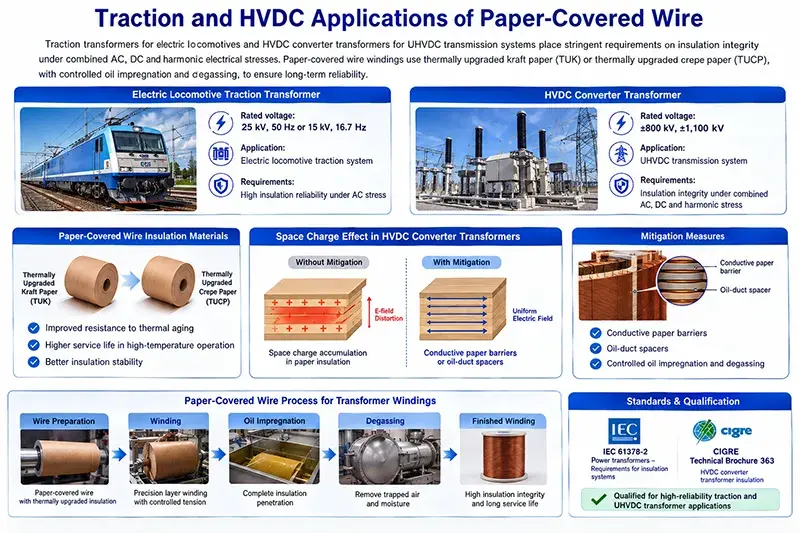
Traction transformers for electric locomotives (rated at 25 kV, 50 Hz or 15 kV, 16.7 Hz) and HVDC converter transformers for ultra-high-voltage direct-current (UHVDC) transmission systems (rated ±800 kV, ±1,100 kV) impose stringent requirements on insulation integrity under combined AC, DC, and harmonic electrical stresses. Paper-covered wire windings in these applications employ thermally upgraded kraft paper (TUK) or thermally upgraded crepe paper (TUCP) to enhance resistance to thermal aging, coupled with precisely controlled oil impregnation and degassing processes. The DC component present in valve windings of HVDC converter transformers induces space charge accumulation within the paper insulation, potentially distorting the electric field distribution; modern designs mitigate this effect using conductive paper barriers or oil-duct spacers. HVDC converter transformer insulation systems are qualified per IEC 61378-2 and CIGRE Technical Brochure 363.
Application Family II: Industrial, Furnace, and Rectifier Transformers
Electric Arc Furnace (EAF) Transformers
EAF transformers for steelmaking are rated from 20 to 200 MVA, with secondary currents reaching up to 80 kA. Their insulation systems must withstand severe short-circuit mechanical stresses, thermal cycling induced by intermittent loading, and harmonic distortion generated by the furnace arc. Low-voltage (LV) windings employ paper-covered wire—typically copper conductors of 2.0–3.5 mm diameter—wrapped with multiple layers of crepe paper to provide mechanical cushioning against short-circuit forces. The LV winding is generally arranged concentrically with the high-voltage (HV) winding; the use of paper-covered wire enables tight, layer-by-layer winding, which is essential to achieve the required impedance voltage (commonly 5–12% for EAF applications). Water-cooled short-circuit busbars and current-carrying leads connect to the LV winding terminals via paper-insulated transition zones, where paper-covered wire is augmented with additional crepe paper or Diamond Dotted Paper (DDP) layers.
Rectifier Transformers for Electrochemical Applications
Rectifier transformers supplying electrolytic cells for aluminum, copper, zinc, and chlorine production operate at secondary voltages of 50–800 V and secondary currents of 5–80 kA. Their LV windings commonly utilize paper-covered wire—frequently in the form of rectangular paper-wrapped copper strip or continuous paper-wrapped cable—to accommodate high current density and ensure reliable oil-immersed operation. The DC component imposed on the LV winding insulation by rectifier circuits (thyristor- or diode-based) is well tolerated by paper–oil insulation systems, owing to their inherently high DC dielectric strength (approximately 5–10 times their AC dielectric strength). Harmonic currents (predominantly 5th, 7th, 11th, and 13th order) introduce additional eddy current losses; these are mitigated through conductor transposition of paper-covered wire or by employing Copper-in-Tube Cable (CTC).
Induction Heating and Welding Transformers
Induction heating transformers operate across a frequency range of 1 kHz to 500 kHz. Medium-frequency units (1–10 kHz) typically use paper-covered wire for the primary (grid-side) winding, while the secondary (resonant tank) winding employs Litz wire or hollow copper tubing. Paper-covered wire’s suitability for frequencies up to approximately 5 kHz allows cost-effective primary winding construction. Resistance welding transformers (for spot, projection, and seam welding) operate at line frequency (50/60 Hz), delivering very high secondary currents (10–50 kA); their heavy-duty primary windings rely on paper-covered wire. The thermal cycling associated with intermittent welding operation (duty cycle 10–50%) necessitates paper-covered wire insulated with thermally upgraded kraft paper (TUK) to ensure extended service life under repeated thermal stress.
Application Family III: Specialty and Renewable Energy Transformers
Wind Turbine Step-Up Transformers
Wind turbine step-up transformers (typically 1–10 MVA), installed either inside turbine nacelles or in adjacent pad-mounted enclosures, require insulation systems capable of withstanding mechanical vibration, thermal cycling induced by variable wind loading, and stringent space constraints. Paper-covered wire windings provide effective vibration damping and reliable oil-immersed operation under these conditions—the paper layer absorbs mechanical energy generated by magnetostriction-driven core vibrations. These transformers operate predominantly at partial load (average 30–60% of rated capacity), with intermittent full-load peaks; thus, their insulation systems must be rated for cyclic thermal stress. Ester-based dielectric fluids—either synthetic or natural—are increasingly adopted in wind turbine transformers due to their environmental safety profile, and paper-covered wire is fully compatible with such fluids.
Solar PV and Energy Storage Step-Up Transformers
PV inverter transformers and battery energy storage system (BESS) step-up transformers (typically 1–20 MVA) operate at moderate average load factors but experience pronounced daily and seasonal load fluctuations. In these applications, paper-covered wire windings benefit from the paper layer’s stable dielectric performance across wide temperature ranges and its proven reliability in oil-immersed service. Outdoor installation with weatherproof enclosures necessitates that paper-covered wire windings be fully sealed within oil-filled tanks, minimizing air ingress. Natural ester fluids (e.g., FR3, Envirotemp FR3) are widely used to meet fire safety requirements (K-class fluid, flash point >300 °C) and environmental compatibility targets; field experience over multiple years confirms that paper-covered wire exhibits comparable aging behavior in natural esters relative to mineral oil.
Traction Transformers for High-Speed Rail
High-speed rail traction transformers—rated at 25 kV, 50 Hz (European systems) or 25 kV, 60 Hz (Asian systems)—are mounted onboard within confined electrical equipment compartments, imposing extreme limitations on weight and volume while demanding exceptionally high reliability. Paper-covered wire windings support compact, lightweight transformer designs without compromising the dielectric integrity required for 25 kV insulation class. These units endure continuous mechanical vibration from train motion and significant thermal cycling due to highly variable load profiles; the inherent mechanical damping properties of paper-covered wire contribute directly to extended service life under such demanding conditions. Compliance with fire safety requirements per EN 45545-2 HL3 is achieved through the use of high-flash-point ester or synthetic fluids, with paper-covered wire demonstrating full compatibility. Key applicable standards include IEC 60310 (traction transformers), IEC 60851 (tests on winding wires), and IEC 60076 (general requirements for power transformers).
Quality Inspection and Certification
Material-Level Testing
Paper-covered wire manufacturing requires comprehensive quality control of incoming paper materials and finished wire products. Paper-level tests include: (i) Thickness, per IEC 60554-2 (measured with micrometer; tolerance ±10%); (ii) Tensile strength, per ASTM D202 (machine direction ≥4.5 kN/m, cross direction ≥2.0 kN/m for standard kraft paper); (iii) Moisture content, per ASTM D644 (≤8% as supplied; ≤0.5% after vacuum drying); (iv) Ash content, per ASTM D586 (≤1%); (v) Conductivity of water extract, per IEC 60554-2 (≤4 mS/m); (vi) pH, per ASTM D4940 (6.5–8.5); and (vii) Dielectric strength, per ASTM D149 (≥8 kV/mm in air; ≥30 kV/mm after oil impregnation). Conductor testing follows the IEC 60317 series and ASTM B49/B3 standards for round copper and aluminum conductors.
Wire-Level Testing
Finished paper-covered wire undergoes electrical and mechanical testing per IEC 60851, ASTM B286, and GB/T 7672: (i) Continuity test to confirm absence of conductor breakage; (ii) Dielectric breakdown voltage test using 50 Hz or 60 Hz AC voltage applied between conductor and outer electrode (minimum 2.5 kV for 2-layer wrapping, increasing with number of layers); (iii) Insulation resistance test per IEC 60851-5 (typically >1,000 MΩ·km at 500 V DC); (iv) Paper overlap verification (visual inspection; typical requirement: 30–60% overlap); (v) Paper adhesion test (peel test; ≥0.5 N/cm); (vi) Dimensional accuracy (diameter tolerance ±0.03 mm for wires up to 2.5 mm in diameter); (vii) Flexibility/bend test (helical winding on mandrel with diameter 5–10× wire diameter, without paper cracking). Aging tests on finished wire include 7-day thermal exposure at 150 °C, followed by dielectric and mechanical retesting.
System-Level Testing in Transformer Manufacturing
Paper-covered wire windings undergo additional testing after coil winding but prior to transformer assembly: (i) Impulse voltage test per IEC 60076-3, applying a 1.2/50 μs standard lightning impulse wave to verify inter-turn and inter-winding insulation integrity; (ii) Applied voltage test (power-frequency withstand test) per IEC 60076-3; (iii) Partial discharge (PD) measurement per IEC 60270 (typically <10 pC at 1.5× rated voltage for qualified windings); (iv) tanδ measurement per IEC 60250 (typically 0.002–0.005 at 50 Hz for oil-impregnated paper-covered wire windings); (v) DC insulation resistance per IEEE C57.12.90 (typically >1,000 MΩ at 5 kV); (vi) Thermal cycling test simulating operational transformer load cycles (typically 5–10 cycles before final assembly). These tests ensure that paper-covered wire windings satisfy the stringent reliability requirements of modern transformer systems.
Conclusion
Paper-covered wire remains a fundamental winding material in modern transformer systems, exerting influence across dielectric, thermal, mechanical, electrical efficiency, reliability, and service life dimensions. Its unique combination—oil-impregnated paper insulation, excellent compatibility with conductors, mature manufacturing processes, and cost-effectiveness—renders paper-covered wire irreplaceable for oil-immersed power and distribution transformers, traction transformers, furnace transformers, and rectifier transformers. A comprehensive understanding of the multi-dimensional impact of paper-covered wire on overall transformer system performance enables optimized material selection, precise control of manufacturing processes, and effective operational maintenance strategies. As ultra-high-voltage (UHV) transmission, renewable energy integration, and high-power industrial applications continue to expand, paper-covered wire will retain its critical role in ensuring transformer reliability and efficiency for decades to come.