


1 Introduction
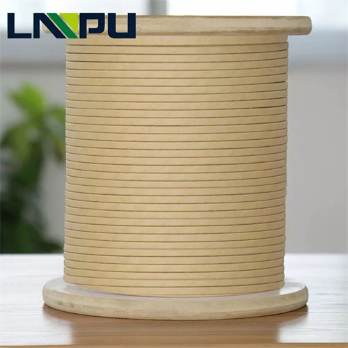
Transformer coil is the core electromagnetic component of high voltage electrical equipment such as oil-immersed power transformer, oil-immersed rectifier transformer, mining transformer, series reactor, high voltage instrument transformer, high voltage bushing. Its manufacturing quality directly determines the electrical performance, mechanical strength, insulation reliability, service life, and operational safety of the transformer. Paper covered wire is an insulated winding wire that uses insulation paper tape such as cable paper, telephone paper, high voltage cable paper, inter-turn insulation paper wrapped around the surface of copper conductor or aluminum conductor, and is the key raw material for oil-immersed transformer coil manufacturing.
The application of paper covered wire in transformer coil manufacturing is a key technical issue faced by winding engineers, transformer manufacturing process engineers, and electrical designers. Based on IEC 60554, IEC 60296, IEC 60076, GB/T 7969, GB/T 10580, JB/T 8740 and other international and domestic standards, this article systematically describes the application technology and engineering practice of paper covered wire in transformer coil manufacturing from eight dimensions including transformer coil and paper covered wire overview, paper covered wire coil pre-treatment, cylindrical coil, disc coil, helical and continuous coil, quality control, application cases, and summary.
2 Transformer Coil and Paper Covered Wire Overview
2.1 Transformer Coil Classification
Transformer coil classification by voltage class: low voltage coil, medium voltage coil, high voltage coil, UHV coil. Transformer coil classification by current capacity: small current coil, medium current coil, high current coil, ultra high current coil. Transformer coil classification by structure type: cylindrical coil, disc coil, helical coil, continuous coil, interleave coil, inner shield coil.
2.2 Cylindrical Coil
Cylindrical coil is a concentric cylindrical coil that uses round conductor or flat conductor spirally wound on coil former or temporary support. Cylindrical coil has simple structure, convenient winding, suitable for 35 kV and below small medium transformer low voltage coil, voltage transformer coil, small capacity transformer high voltage coil. Cylindrical coil layer number 1 to 10 layers, each layer turn number 10 to 200 turns, conductor diameter 0.50 to 3.00 mm. Cylindrical coil insulation adopts inter-layer insulation paper + end insulation paper + spacer + end ring.
2.3 Disc Coil
Disc coil is a coil that uses flat conductor wound into disc shaped segments, multiple segments connected in series along axial direction. Disc coil is suitable for 35 kV and above large medium transformer high voltage coil, 35 kV to 110 kV medium transformer medium voltage coil, high current transformer low voltage coil. Disc coil segment number 10 to 200 discs, each disc turn number 5 to 50 turns, conductor width 2.00 to 16.00 mm, thickness 0.80 to 5.60 mm. Disc coil insulation adopts inter-turn insulation + inter-disc insulation + inter-segment insulation + electrostatic shield insulation.
2.4 Helical and Continuous Coil
Helical coil is a multi-layer helical coil that uses flat conductor spirally wound on coil former. Helical coil is suitable for high current low voltage coil, current above 1000 A, conductor width 4.00 to 16.00 mm, thickness 1.50 to 5.60 mm, turn number 5 to 50 turns, layer number 1 to 6 layers.
Continuous coil is a coil that uses flat conductor on special winding machine to continuously wind multiple disc segments, no joints between disc segments, continuously connected in series. Continuous coil is suitable for 35 kV to 500 kV large medium transformer high voltage coil, disc segment number 20 to 300 discs, each disc turn number 1 to 20 turns, conductor width 2.00 to 12.00 mm, thickness 0.80 to 4.00 mm.
2.5 Paper Covered Wire Application in Coil
The application of paper covered wire in transformer coil mainly includes six major categories. Cylindrical coil application: low voltage cylindrical coil adopts DLZ cable paper wrapped round copper wire, inter-turn insulation adopts DH telephone paper, inter-layer insulation adopts DMD composite paper. Disc coil application: high voltage disc coil adopts DLZ / GDL high voltage cable paper wrapped flat copper wire, inter-turn insulation adopts DH telephone paper, inter-disc insulation adopts insulation pressboard + spacer. Helical coil application: low voltage helical coil adopts DLZ cable paper wrapped flat copper wire, inter-turn insulation adopts DH telephone paper, inter-layer insulation adopts insulation pressboard + spacer. Continuous coil application: high voltage continuous coil adopts DLZ / GDL high voltage cable paper wrapped flat copper wire, inter-turn insulation adopts DH telephone paper, inter-disc insulation adopts insulation pressboard + oil duct spacer. Interleave coil application: UHV interleave coil adopts GDL high voltage cable paper wrapped flat copper wire, inter-turn insulation adopts GDL high voltage cable paper, inter-disc insulation adopts insulation pressboard + oil duct + electrostatic shield. Continuously transposed conductor CTC coil application: large power transformer low voltage coil adopts continuously transposed conductor, enameled flat wire + paper tape wrapping, 5 to 80 enameled flat wires transposition.
3 Paper Covered Wire Coil Pre-treatment
3.1 Paper Covered Wire Incoming Inspection
Paper covered wire incoming inspection items: conductor specification, conductor surface, insulation paper type, insulation paper thickness, insulation paper width, insulation paper layer number, insulation paper overlap rate, insulation paper appearance, insulation paper moisture content, coil breakdown voltage, coil insulation resistance, coil dielectric loss.
Conductor specification inspection: round conductor diameter tolerance plus minus 0.005 to plus minus 0.030 mm, flat conductor width tolerance plus minus 0.02 to plus minus 0.05 mm, flat conductor thickness tolerance plus minus 0.01 to plus minus 0.04 mm. Conductor surface should be clean, free of oxide layer, free of oil, free of moisture, roughness Ra 0.8 to 1.6 micrometers. Insulation paper inspection: DLZ / GDL cable paper thickness tolerance plus minus 0.005 mm, width tolerance plus minus 0.1 mm, moisture content below 8%, ash content below 1.0%, pH value 6.5 to 8.0. Insulation paper should be flat, free of crease, free of damage, free of stain.
3.2 Paper Covered Wire Pre-treatment
Paper covered wire pre-treatment process: paper covered wire storage temperature 5 to 35 degrees Celsius, relative humidity 30% to 70%, storage period within 1 year. Before use, paper covered wire should be placed in coil workshop environment temperature 20 to 30 degrees Celsius, relative humidity 40% to 60% for 24 to 48 hours, to balance the paper covered wire temperature and humidity with the workshop, to avoid moisture absorption or water loss during winding. Before use, paper covered wire surface should be cleaned, use clean lint-free cloth or soft brush to remove surface dust, paper scraps, impurities. Chemical cleaners should not be used, to avoid damage to insulation paper surface.
3.3 Winding Equipment and Former Inspection
Winding machine precision requirement: wire arrangement precision plus minus 0.1 mm, turn count precision plus minus 0.1 turn, tension control precision plus minus 0.1 Newton, speed control precision plus minus 1 rpm, winding machine should be calibrated regularly, calibration period not exceeding 12 months.
Coil former preparation: cylindrical coil adopts insulation pressboard + end ring former, helical coil adopts insulation pressboard + end ring + spacer former, continuous coil adopts insulation paper tube + end ring + spacer + electrostatic shield former, disc coil adopts insulation paper tube + end ring + spacer + inter-segment pad former. Coil support inspection: insulation pressboard thickness tolerance plus minus 0.05 mm, width tolerance plus minus 0.1 mm, moisture content below 6%, end ring should be flat, no warping, inner outer diameter tolerance plus minus 0.2 mm, spacer should be straight, no bending, width tolerance plus minus 0.1 mm.
3.4 Winding Environment Requirement
Winding environment temperature: cylindrical coil 18 to 28 degrees Celsius, disc coil 20 to 30 degrees Celsius, helical coil 20 to 30 degrees Celsius, continuous coil 22 to 28 degrees Celsius. Winding environment relative humidity 40% to 60%, avoid high humidity or dry environment. Winding environment should be clean, air dust content below 0.5 mg per cubic meter, avoid dust contamination of insulation paper.
4 Cylindrical Coil
4.1 Cylindrical Coil Winding Process
Cylindrical coil winding steps: prepare coil former and end ring, end ring bonded on insulation paper tube, form coil support. Coil start lead fabrication, lead adopts copper foil or copper stranded wire, wrapped with insulation paper for insulation. Place inter-layer insulation paper, inter-layer insulation paper should be flat, overlap 5 to 10 mm. Coil winding, paper covered wire under tension control spirally wound, turn-to-turn close arrangement, each layer turn number conforms to drawing requirement. Place inter-layer insulation paper, wind next layer, repeat until all layers completed. Coil end lead fabrication. Coil end insulation wrapping, use insulation paper tape to wrap coil end, strengthen end insulation. Coil binding, use white cloth tape or polyester tape to bind coil, fix shape.
4.2 Cylindrical Coil Winding Parameter and Insulation Structure
Cylindrical coil winding parameter: paper covered wire tension 5 to 15 Newton, winding speed 5 to 30 rpm, turn-to-turn distance 0 to 0.5 mm, inter-layer distance 0.5 to 2.0 mm. Cylindrical coil layer number 1 to 10 layers, each layer turn number 10 to 200 turns, coil height 50 to 500 mm, coil inner diameter 30 to 200 mm.
Cylindrical coil insulation structure: inter-turn insulation adopts paper covered wire insulation paper, typical 0.05 to 0.13 mm, breakdown voltage 300 to 1600 V. Inter-layer insulation adopts insulation pressboard or DMD composite paper, typical 0.2 to 1.0 mm, breakdown voltage 5000 to 20000 V. End insulation adopts insulation pressboard or insulation paper tape wrapping, typical 1.0 to 3.0 mm, breakdown voltage 10000 to 30000 V. Bottom insulation adopts insulation paper tube, typical 2.0 to 6.0 mm, breakdown voltage 20000 to 50000 V.
4.3 Cylindrical Coil Quality Control
Cylindrical coil quality control items: turn number check, coil height check, coil outer diameter check, coil inner diameter check, inter-layer insulation check, end insulation check, lead position check, lead polarity check, coil DC resistance check, coil insulation resistance check, coil inter-turn insulation check. Turn number deviation not exceeding plus minus 0.5 turn, coil height deviation plus minus 2 mm, coil outer diameter deviation plus minus 1 mm, coil inner diameter deviation plus minus 1 mm, coil DC resistance deviation plus minus 2%, coil insulation resistance not less than 1000 MΩ.
5 Disc Coil
5.1 Disc Coil Winding Process
Disc coil winding steps: prepare coil former and spacer, spacer evenly distributed on coil circumference. Wind first disc, paper covered wire on special winding machine winds disc shaped segment, turn number conforms to drawing requirement, after each disc winding completed use white cloth tape for temporary binding. Place inter-disc insulation, inter-disc insulation adopts insulation pressboard + oil duct spacer. Wind second disc, and so on, wind all disc numbers. Inter-disc connection, inter-disc connection adopts welding or brazing, connection area wrapped with insulation paper. Coil end insulation wrapping. Coil arrangement and binding.
5.2 Disc Coil Winding Parameter and Insulation Structure
Disc coil winding parameter: paper covered wire tension 10 to 30 Newton, winding speed 3 to 15 rpm, each disc turn number 5 to 50 turns, disc number 10 to 200 discs, each disc radial dimension 20 to 200 mm, each disc axial dimension 10 to 80 mm, inter-disc oil duct width 4 to 12 mm, spacer width 10 to 30 mm, spacer thickness 1.0 to 3.0 mm.
Disc coil insulation structure: inter-turn insulation adopts paper covered wire insulation paper, typical 0.05 to 0.13 mm, breakdown voltage 300 to 1600 V. Inter-disc insulation adopts insulation pressboard + oil duct spacer, typical 0.5 to 2.0 mm insulation pressboard, breakdown voltage 5000 to 30000 V. Inter-segment insulation adopts insulation pressboard + inter-segment pad, typical 1.0 to 4.0 mm, breakdown voltage 10000 to 50000 V. Electrostatic shield insulation adopts insulation pressboard + metal foil shield, typical 0.5 to 1.5 mm, breakdown voltage 10000 to 30000 V. End insulation adopts insulation pressboard + angle ring, typical 2.0 to 8.0 mm, breakdown voltage 30000 to 80000 V.
5.3 Disc Coil Quality Control
Disc coil quality control items: each disc turn number check, disc number check, each disc radial dimension check, each disc axial dimension check, inter-disc connection check, inter-disc insulation check, spacer position check, electrostatic shield check, coil DC resistance check, coil insulation resistance check, coil inter-turn insulation check, coil inter-disc insulation check. Each disc turn number deviation plus minus 0.2 turn, disc number deviation plus minus 1 disc, each disc radial dimension deviation plus minus 1 mm, each disc axial dimension deviation plus minus 0.5 mm, inter-disc connection resistance deviation plus minus 3%, coil DC resistance deviation plus minus 2%, coil insulation resistance not less than 1000 MΩ.
6 Helical and Continuous Coil
6.1 Helical Coil
Helical coil winding steps: prepare coil former and end ring, end ring made of insulation pressboard. Coil start lead fabrication, lead adopts copper foil. Wind first turn, paper covered wire on special winding machine spirally wound, turn number conforms to drawing requirement. Place inter-layer insulation, inter-layer insulation adopts insulation pressboard + spacer. Wind second turn, and so on. Coil end lead fabrication. Coil end insulation wrapping and binding.
Helical coil winding parameter: paper covered wire tension 15 to 50 Newton, winding speed 2 to 10 rpm, turn number 5 to 50 turns, layer number 1 to 6 layers, each layer 1 to 10 turns, coil radial dimension 20 to 200 mm, coil axial dimension 100 to 800 mm. Helical coil insulation structure: inter-turn insulation typical 0.08 to 0.13 mm, breakdown voltage 600 to 1600 V. Inter-layer insulation typical 1.0 to 3.0 mm, breakdown voltage 10000 to 40000 V. End insulation typical 3.0 to 10.0 mm, breakdown voltage 30000 to 80000 V. Bottom insulation typical 4.0 to 12.0 mm, breakdown voltage 30000 to 80000 V.
6.2 Continuous Coil
Continuous coil winding steps: prepare coil former and electrostatic shield, electrostatic shield adopts metal foil + insulation paper. Coil start lead fabrication. Wind first disc, paper covered wire on special winding machine winds disc shaped segment. Reverse wind second disc, winding machine automatic direction change, wind reverse disc. Inter-disc connection realized by winding machine automatic transposition. Wind all disc numbers. Coil end lead fabrication. Coil end insulation wrapping and binding.
Continuous coil winding parameter: paper covered wire tension 10 to 40 Newton, winding speed 2 to 8 rpm, each disc turn number 1 to 20 turns, disc number 20 to 300 discs, each disc radial dimension 30 to 250 mm, each disc axial dimension 8 to 30 mm, inter-disc oil duct width 4 to 8 mm, electrostatic shield number 1 to 6 layers. Continuous coil insulation structure: inter-turn insulation typical 0.08 to 0.13 mm, breakdown voltage 600 to 1600 V. Inter-disc insulation adopts insulation pressboard + oil duct spacer, typical 0.5 to 1.5 mm insulation pressboard + 4 to 8 mm oil duct, breakdown voltage 10000 to 30000 V. Electrostatic shield insulation adopts metal foil + insulation paper, typical 0.05 mm copper foil + 0.5 to 1.0 mm insulation paper, breakdown voltage 10000 to 20000 V. End insulation adopts insulation pressboard + angle ring + electrostatic shield, typical 3.0 to 12.0 mm, breakdown voltage 30000 to 100000 V.
6.3 Helical and Continuous Coil Quality Control
Helical and continuous coil quality control items: turn number check, disc number check, dimension check, connection check, insulation check, DC resistance check, insulation resistance check, inter-turn insulation check, induced voltage withstand check, applied power frequency voltage withstand check, impulse voltage check, partial discharge check. Turn number deviation plus minus 0.2 turn, disc number deviation plus minus 1 disc, radial dimension deviation plus minus 1 mm, axial dimension deviation plus minus 0.5 mm, connection resistance deviation plus minus 3%, DC resistance deviation plus minus 2%, insulation resistance not less than 1000 MΩ.
6.4 Vacuum Pressure Impregnation Key Points
Vacuum pressure impregnation is the key insulation treatment process of transformer coil. Pre-drying temperature 100 to 120 degrees Celsius, pre-drying time 24 to 72 hours, pre-drying vacuum 50 to 100 Pa, pre-drying endpoint is coil moisture content below 0.5%. Vacuum pressure impregnation parameter: vacuum below 50 Pa, hold for 1 to 4 hours, pressure 0.2 to 0.5 MPa, hold for 4 to 12 hours, impregnant temperature 50 to 70 degrees Celsius, impregnation time 8 to 24 hours. Common impregnant: 25 transformer oil, kinematic viscosity 13 mm² per s, namely at 50 degrees Celsius, flash point 140 degrees Celsius, breakdown voltage not less than 35 kV, is the standard oil for power transformer. 45 transformer oil, is the standard oil for high voltage transformer, used for 110 kV and above high voltage equipment. After impregnation inspection: coil insulation resistance not less than 1000 MΩ, coil dielectric loss tangent not higher than 0.005, namely at 90 degrees Celsius. Coil assembly steps: low voltage coil set on iron core column, insulation tube placed between coil and iron core, high voltage coil set outside low voltage coil, insulation tube and oil duct spacer placed between high and low voltage coil, pressure plate placed on coil top, use pressure screw to compress coil. Coil axial compression force: 35 kV coil 0.1 to 0.2 MPa, 110 kV coil 0.2 to 0.3 MPa, 220 kV coil 0.3 to 0.4 MPa, 500 kV coil 0.4 to 0.5 MPa. Lead assembly: lead adopts copper foil or copper stranded wire, lead insulation adopts crepe paper + insulation varnish or heat shrink tube, lead and coil connection adopts cold pressure welding or brazing.
7 Quality Control
7.1 Coil Basic Test
Coil test items: coil DC resistance measurement, coil insulation resistance measurement, coil dielectric loss measurement, coil inter-turn insulation test, coil induced voltage withstand test, coil applied power frequency voltage withstand test, coil impulse voltage test, coil partial discharge test. Coil DC resistance deviation plus minus 2%, inter-phase DC resistance deviation plus minus 1%, measurement equipment is DC resistance bridge or micro-ohmmeter, measurement precision plus minus 0.5%. Coil insulation resistance not less than 1000 MΩ, absorption ratio not less than 1.3, polarization index not less than 1.5, measurement voltage 500 V to 5000 V. Coil dielectric loss tangent not higher than 0.005, namely at 90 degrees Celsius, test voltage 1000 V to 10000 V, frequency 50 Hz.
7.2 Coil Insulation Test
Coil inter-turn insulation test: adopt impulse voltage test, test voltage 1.5 to 3 times rated voltage, impulse waveform 1.2/50 μs, impulse times at least 3, there should be no discharge, no breakdown, no flashover during test. Coil induced voltage withstand test: test voltage 1.5 to 2 times rated voltage, frequency 100 to 400 Hz, test time 60 s, there should be no discharge, no breakdown, no flashover during test.
Coil applied power frequency voltage withstand test: test voltage determined by voltage class, typical 35 kV coil 85 kV, 110 kV coil 200 kV, 220 kV coil 395 kV, 500 kV coil 680 kV, test time 60 s, there should be no discharge, no breakdown, no flashover during test. Coil impulse voltage test: typical 110 kV coil 480 kV, 220 kV coil 945 kV, 500 kV coil 1550 kV, waveform 1.2/50 μs, test times positive and negative polarity each 3 times.
7.3 Partial Discharge and Temperature Rise Short Circuit Test
Coil partial discharge test: test voltage 1.1 to 1.5 times rated voltage, test time 30 to 60 minutes, discharge amount below specified value, typical 110 kV coil discharge amount below 100 pC, 220 kV coil discharge amount below 50 pC, 500 kV coil discharge amount below 30 pC.
Coil temperature rise test: measure coil temperature rise under rated load, oil-immersed transformer coil temperature rise not exceeding 65 K, namely oil natural circulation, 80 K, namely oil forced circulation, special design 60 K. Coil short circuit test: short circuit current 25 to 49 times rated current, duration 0.5 to 2 s, test times 3, after test coil should be no deformation, no damage, coil DC resistance deviation not exceeding plus minus 2%.
8 Application Case and Summary
8.1 Application Case
Application case one: 110 kV 50 MVA oil-immersed power transformer high voltage coil, adopts GDL-0.13 high voltage cable paper wrapped flat copper wire, conductor specification 10 by 3.15 mm, each disc turn number 8 to 15 turns, disc number 80 to 120 discs, continuous coil, inter-disc oil duct 8 mm, electrostatic shield 3 layers, vacuum pressure impregnation 45 transformer oil, operating voltage 110 kV, coil dielectric loss tangent 0.003, insulation class A, service life over 30 years.
Application case two: 220 kV 180 MVA oil-immersed power transformer high voltage coil, adopts GDL-0.13 / GDL-0.17 high voltage cable paper wrapped flat copper wire, conductor specification 8 by 3.15 to 12 by 4 mm, each disc turn number 6 to 12 turns, disc number 150 to 200 discs, continuous coil, inter-disc oil duct 10 mm, electrostatic shield 4 layers, vacuum pressure impregnation 45 transformer oil, operating voltage 220 kV, coil dielectric loss tangent 0.003, insulation class A, service life over 30 years.
Application case three: 500 kV 1000 MVA oil-immersed power transformer high voltage coil, adopts GDL-0.17 high voltage cable paper wrapped flat copper wire, conductor specification 8 by 3.55 to 14 by 4.5 mm, each disc turn number 3 to 8 turns, disc number 250 to 350 discs, continuous coil, inter-disc oil duct 12 mm, electrostatic shield 6 layers, vacuum pressure impregnation 45 transformer oil, operating voltage 500 kV, coil dielectric loss tangent 0.0025, insulation class A, service life over 30 years.
Application case four: 35 kV 5000 kVA oil-immersed rectifier transformer low voltage coil, adopts DLZ-0.13 cable paper wrapped flat copper wire, conductor specification 12 by 4 mm, turn number 15 to 25 turns, layer number 3 to 4 layers, helical coil, inter-layer insulation 1.5 mm insulation pressboard, vacuum pressure impregnation 25 transformer oil, operating voltage 35 kV, current 5000 A, insulation class A.
Application case five: 110 kV 6300 kVA mining transformer high voltage coil, adopts DLZ-0.13 cable paper wrapped flat copper wire, conductor specification 6 by 2 to 10 by 3.15 mm, disc number 40 to 80 discs, disc coil, inter-disc oil duct 6 mm, vacuum pressure impregnation 25 transformer oil, operating voltage 110 kV, strict explosion proof requirement, insulation class A.
Application case six: 10 kV 100 kvar series reactor coil, adopts DLZ-0.13 cable paper wrapped aluminum wire, conductor specification 8 by 3.15 to 12 by 4 mm, disc number 30 to 60 discs, disc coil, inter-disc oil duct 6 mm, vacuum pressure impregnation 25 transformer oil, operating voltage 10 kV, high harmonic content, insulation class A.
8.2 Design Selection Recommendation
Design selection recommendation one: 35 kV and below small medium transformer low voltage coil, recommend cylindrical coil + DLZ-0.05 / DLZ-0.08 cable paper wrapped round copper wire, 25 transformer oil impregnation. Design selection recommendation two: 35 kV to 110 kV medium transformer high voltage coil, recommend continuous coil + DLZ-0.13 / GDL-0.13 high voltage cable paper wrapped flat copper wire, electrostatic shield 2 to 3 layers, 45 transformer oil impregnation. Design selection recommendation three: 110 kV to 220 kV medium large transformer high voltage coil, recommend continuous coil + GDL-0.13 / GDL-0.17 high voltage cable paper wrapped flat copper wire, electrostatic shield 3 to 5 layers, 45 transformer oil impregnation. Design selection recommendation four: 220 kV to 500 kV large power transformer high voltage coil, recommend continuous coil + GDL-0.17 high voltage cable paper wrapped flat copper wire, electrostatic shield 4 to 6 layers, 45 transformer oil impregnation. Design selection recommendation five: high current rectifier transformer low voltage coil, recommend helical coil + DLZ-0.13 cable paper wrapped flat copper wire, 25 transformer oil impregnation. Design selection recommendation six: mining explosion proof transformer coil, recommend disc coil + DLZ-0.13 cable paper wrapped flat copper wire, 25 transformer oil impregnation, strict explosion proof requirement.
8.3 Summary
The application of paper covered wire in transformer coil manufacturing covers six major coil structures including cylindrical coil, disc coil, helical coil, continuous coil, interleave coil, continuously transposed conductor coil, and is the key process for the manufacturing of high voltage electrical equipment such as oil-immersed power transformer, rectifier transformer, mining transformer, series reactor, high voltage instrument transformer, high voltage bushing.
The coil manufacturing process covers 7 key process links including paper covered wire incoming inspection, paper covered wire pre-treatment, winding equipment inspection, coil former preparation, coil winding, coil assembly. The coil quality control covers 10 test items including coil DC resistance, insulation resistance, dielectric loss, inter-turn insulation, induced voltage withstand, applied power frequency voltage withstand, impulse voltage, partial discharge, temperature rise, short circuit.
The application cases cover 35 kV to 500 kV oil-immersed power transformer, 35 kV rectifier transformer, 110 kV mining transformer, 10 kV series reactor and other high voltage electrical equipment. The design selection should be based on six major principles: coil type, conductor specification, insulation class, electrical performance, mechanical strength, operating voltage.
With the continuous evolution of key raw materials and manufacturing equipment such as high performance cellulose paper, high dielectric strength insulation paper, high strength insulation pressboard, continuously transposed conductor, intelligent winding machine, vacuum pressure impregnation equipment, high precision coil test equipment, as well as the continuous development of UHV power transformer, UHV power transformer, new energy transformer, rail transit transformer, smart grid transformer and other strategic emerging industries, the application technology of paper covered wire in transformer coil manufacturing will be further improved and expanded, providing a solid foundation for transformer manufacturing and power system development.
Reference standards: IEC 60554 total 6 parts / IEC 60243 / IEC 60296 / IEC 60076-1 to 60076-11 / ASTM D 149 / ASTM D 2413 / ASTM D 3487 / GB/T 3953 / GB/T 3955 / GB/T 7969 / GB/T 7970 / GB/T 10580 / GB 2536 / JB/T 8740 / JB/T 50132 / DL/T 580 / GB/T 1094.
Contact Information: E-mail office@cnlpzz.com, WhatsApp 0086-19337889070, Zhengzhou LP Industry Co., Ltd.
- Email: office@cnlpzz.com
- WhatsApp: 0086-19337889070
- Company: Zhengzhou LP Industry Co., Ltd.