
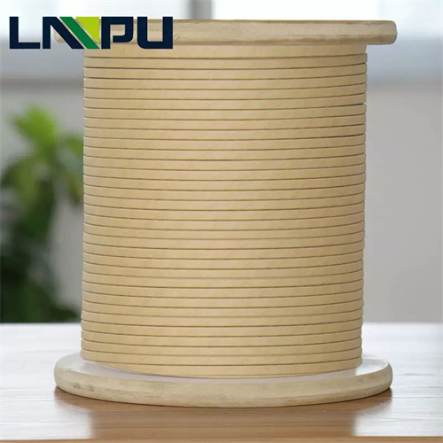
Paper-covered wire is the core insulated conductor for windings in oil-immersed transformers. Its structure consists of a conductor (copper or aluminum, round or flat wire) wrapped with multiple layers of insulating paper—such as cable paper, crepe paper, Dennison paper, or aromatic polyamide paper (Nomex)—and impregnated with insulating varnish. Power plant transformers—including main transformers, station service transformers, excitation transformers, and start-up/standby transformers—operate under demanding conditions: high voltage ratings (10.5 kV, 35 kV, 110 kV, 220 kV, 500 kV), large capacities (tens to over one thousand MVA), long service life (30–40 years), and harsh operational environments (oil temperature 95–105°C, short-circuit stress, overvoltage events). These requirements impose systematic technical demands on paper-covered wire regarding material selection, insulation performance, transposition capability, and mechanical properties.
This document addresses material selection, technical specifications, application scenarios, manufacturing processes, and failure modes of paper-covered wire for power plant transformers—providing technical reference for design, operation & maintenance, and procurement engineers.
I. Functional Role of Paper-Covered Wire in Power Plant Transformers
Paper-covered wire serves the following critical functions in power plant transformers:
1. Electrical Insulation Function
In oil-immersed transformers, paper-covered wire operates within a “turn-to-turn insulation + oil duct insulation” configuration. The insulating paper and transformer oil constitute a composite cellulose-oil insulation system, providing turn-to-turn, phase-to-phase, and ground insulation. The dielectric strength of insulating paper (typically 1.5–3 kV per layer, thickness 0.05–0.13 mm) synergizes with the dielectric properties of mineral oil to determine the winding’s voltage withstand rating.
2. Current Carrying and Current Collecting Function
The copper (or aluminum) conductor carries the operating current. In large power plant main transformers, low-voltage winding currents often reach several kiloamperes—for example:
- 110 kV / 50 MVA main transformer: LV-side current ≈ 260 A;
- 220 kV / 240 MVA main transformer: 35 kV-side current ≈ 3.9 kA.
This necessitates large conductor cross-sectional area, rational current density, and controllable temperature rise.
3. Mechanical Support and Short-Circuit Resistance Function
During system short circuits, main transformers experience enormous electromagnetic forces (proportional to the square of fault current). Paper-covered flat wire, after hot-press forming, forms a robust winding structure capable of withstanding axial and radial short-circuit forces—per GB 1094.5 and IEC 60076-5 short-circuit withstand requirements.
4. Heat Dissipation and Oil Duct Flow Function
Oil ducts (Oil Ducts) are maintained between paper layers of the wire, enabling transformer oil to remove heat from windings via convection. Oil duct width (typically 2–6 mm) is determined by insulating paper width and winding arrangement, directly influencing temperature rise—governed by GB 1094.2 and IEC 60076-2 temperature rise limits.
II. Key Performance Indicators of Paper-Covered Wire for Power Plant Transformers
2.1 Conductor Material and Geometry
Common conductors used in power plant transformers include:
- Electrical Round Copper Wire** (TR round wire, diameters Φ 1.0–Φ 6.0 mm);
- Electrical Flat Copper Wire** (TBR flat wire, thickness a = 0.80–5.60 mm, width b = 3.00–16.00 mm), compliant with GB/T 5584.2 and IEC 60317-0-2;
- Aluminum conductors (LR round wire / LBR flat wire), applied in large transformers to reduce cost and weight, compliant with GB/T 5584.3.
Conductor requirements:
- Purity ≥ 99.9% (copper) or ≥ 99.5% (aluminum), conforming to GB/T 3953 and ASTM B49;
- Resistivity ≤ 0.01724 Ω·mm²/m (at 20°C for copper);
- Surface must be smooth, free of burrs, oxide scale, pits, or other defects.
Surface treatment of the conductor significantly affects paper adhesion quality and insulation strength—copper conductors are commonly subjected to “roughening” or “passivation” treatments to enhance enamel coating bonding.
2.2 Insulating Paper Types and Thermal Classes
Common insulating paper types and their corresponding thermal classes used in power plant transformers (per ANSI/NEMA MW 1000-2018, GB/T 7672, and IEC 60317-0-2) are listed below:
| Paper Type | Thermal Class | Thickness Range | Key Characteristics | Typical Application |
|---|---|---|---|---|
| Cable Paper (DLZ) | 105°C (Class A) | 0.05–0.13 mm | Cellulose-based, low-cost | Small- to medium-size oil-immersed transformers, LV windings |
| High-Voltage Cable Paper (GDLZ) | 105°C (Class A) | 0.05–0.13 mm | High-density, high dielectric strength | Windings rated ≥ 110 kV |
| Dennison Paper | 105°C (Class A) | 0.05–0.10 mm | High mechanical strength, low dielectric loss | Transposed conductors for ≥ 220 kV systems |
| Crepe Paper | 105°C (Class A) | 0.05–0.20 mm (after stretching) | High elasticity, cushioning effect | Lead wires, end-winding insulation |
| Aromatic Polyamide Paper (Nomex 410/414) | 220°C (Class C) | 0.05–0.76 mm | Exceptional high-temperature resistance, mechanical strength, flame retardancy | Class H dry-type transformers, high-temperature oil-immersed transformers |
Key Performance Indicators of Insulating Paper:
- Electrical strength ≥ 8 kV/mm (in air)
- Tensile strength (MD ≥ 5 kN/m)
- Elongation (MD ≥ 8%)
- Moisture content ≤ 8% (as-manufactured)
- Ash content ≤ 1%
- pH value: 6.0–8.0 (neutral)
- Dielectric constant (oil-impregnated state): ~3.5–4.0
- Dielectric loss factor (tan δ) ≤ 0.005 (at 100 °C, 1 kHz)
2.3 Wrapping and Lapping Requirements
Wrapping method for paper-covered wire: Paper tape is helically wrapped with 30–60% overlap; total layers range from 2 to 10 (determined by voltage class). For high-voltage windings of 500 kV power plant main transformers, single paper-covered flat wire insulation thickness may reach 2.0–4.0 mm (total paper tape thickness), equivalent to 16–32 layers of 0.075 mm-thick paper.
Wrapping quality requirements:
- Uniform paper tape tension (to prevent loose or tight wrapping);
- Lapping positions must be staggered (no multi-layer lapping at the same axial location);
- No conductive contaminants, fiber burrs, or air gaps permitted between paper layers;
- Paper tape joints must be flush and free of wrinkles;
- Post-wrapping wire diameter uniformity: ±0.05 mm.
2.4 Impregnation and Drying
After winding, paper-covered wire must undergo vacuum pressure impregnation (VPI) or atmospheric-pressure varnish impregnation:
- Varnish viscosity (25 °C): 300–500 mPa·s;
- Impregnation time: 30–60 min;
- Vacuum level: ≤ 100 Pa;
- Impregnation pressure: 0.2–0.6 MPa;
- Curing temperature: 130–160 °C (Class B) or 150–180 °C (Class F/H).
Post-impregnation, paper-covered wire exhibits significantly improved insulation resistance, dielectric strength, moisture resistance, and mechanical strength. Impregnation quality shall comply with GB/T 11026 and IEC 60851-5.
III. Paper-Covered Wire Selection for Typical Power Plant Transformer Applications
3.1 Main Transformers ≥ 220 kV (High-Voltage Windings)
Operating conditions:
- Operating voltage: 220 kV;
- Capacity: 240–1000 MVA;
- Continuous operation;
- Oil temperature: 95–105 °C;
- Design service life: 30–40 years;
- Short-circuit current withstand: 25–63 kA.
Recommended specifications:
- Conductor: TBR flat copper wire (thickness: 1.60–3.55 mm; width: 6.00–12.50 mm);
- Insulation: 6–8 layers of high-density cable paper (single-layer thickness: 0.075 mm; total thickness ≥ 0.6 mm);
- Paper tape lap rate: 50%;
- Compliance: GB/T 5584.2, GB/T 7672, IEC 60317-0-2.
3.2 110 kV Main Transformers (HV/LV Windings)
Operating conditions:
- Operating voltage: 110 kV;
- Capacity: 31.5–120 MVA;
- Continuous operation with frequent load variations.
Recommended specifications:
- Conductor: TBR flat copper wire (thickness: 1.12–2.50 mm; width: 5.00–10.00 mm);
- Insulation:
- 4–6 layers of high-density cable paper (total thickness ≥ 0.45 mm), or
- 3–5 layers of Dennison paper (total thickness ≥ 0.40 mm);
- Compliance: GB 1094.3, IEC 60076-3.
3.3 Plant Service Transformers & Excitation Transformers (10–35 kV)
Operating conditions:
- Operating voltage: 10.5 kV / 35 kV;
- Capacity: 0.5–10 MVA;
- Elevated operating temperature; vibration-prone environment.
Recommended specifications:
- Conductor: TBR flat copper wire or enameled flat copper wire (paper-covered + enameled composite insulation);
- Insulation: 2–4 layers of cable paper (total thickness ≥ 0.20 mm);
- Compliance: GB 1094.4, IEC 60076-4.
3.4 Starting/Standby Transformers & Auxiliary Transformers
Operating conditions:
- Frequent start-stop cycles; alternating light/heavy loads; outdoor installation.
Recommended specifications:
- Conductor: copper round wire (Φ 1.50–Φ 3.15 mm) or flat copper wire;
- Insulation: 2–3 layers of cable paper, impregnated with epoxy ester or modified epoxy resin;
- Compliance: DL/T 5218, IEEE C57.12.00.
3.5 Class H Dry-Type Power Plant Transformers (High-Temperature Applications)
Operating conditions:
- Operating voltage: 6–35 kV;
- Capacity: 0.8–20 MVA;
- Thermal class H (180 °C); oil-free; high fire-resistance requirement.
Recommended specifications:
- Conductor: enameled flat copper wire with Nomex® paper-covered composite insulation;
- Insulation: 3–5 layers of Nomex® 410 paper (total thickness ≥ 0.30 mm);
- Compliance: GB 1094.11, IEC 60076-11.
IV. Key Manufacturing Process Points for Paper-Covered Wire Used in Power Plant Transformers
4.1 Wrapping Process
Critical process parameters for paper-covered wire:
- Paper tape wrapping speed: 100–400 rpm (dependent on wire size and layer count);
- Paper tape tension: 1.5–5.0 N (adjusted per paper thickness and wire dimensions);
- Paper tape width:
- For round wire: × (0.7–0.9) of wire circumference;
- For flat wire: × (0.5–0.7) of wire width;
- Paper tape joints: “butt lap” or “skew lap” (lap length: 5–15 mm); joint adhesive must be oil-resistant and heat-resistant.
Wrapping equipment requirements:
- Constant-tension control;
- Closed-loop tension feedback;
- Automatic stop-on-break function;
- Automatic wrap-angle adjustment;
- In-line wire diameter measurement.
Wrapping workshop environmental conditions:
- Temperature: 20–28 °C;
- Relative humidity: 40–65%;
- Air cleanliness: ≤ Class 100,000 (to prevent fiber dust contamination).
4.2 Transposed Cable (CTC) Manufacturing
Power plant main transformer low-voltage windings—especially in high-current applications—widely adopt Continuously Transposed Conductors (CTC). CTC consists of multiple enameled flat wires (or paper-wrapped flat wires), typically 5–37 strands, arranged with continuous transposition at a defined pitch and integrally wrapped with insulating paper. Transposition pitch: 40–100 mm; CTC height: 5–25 mm; width: 4–16 mm.
CTC manufacturing requirements:
- Each individual strand must have intact enamel coating;
- Uniform and accurate transposition—no misalignment;
- Outer paper wrapping layer must be mechanically robust;
- Impregnation must be thorough and homogeneous.
CTC manufacturing shall comply with GB/T 11018.1 and IEC 60317-0-4.
4.3 Winding and Assembly
Paper-wrapped wire winding is performed on winding machines:
- Winding mandrel (bobbin) surface roughness: Ra ≤ 1.6 μm;
- Winding tension: 30–80 N (determined by wire cross-section);
- Winding speed: 5–30 rpm (slower for large power transformers);
- End chamfer radius: R ≥ 5 mm (to prevent insulation damage);
- Inter-layer insulation (corrugated paperboard, oil duct spacers) installed per design specifications.
After winding assembly, the unit proceeds to the final assembly process, including:
- Core-and-coil assembly;
- Lead welding;
- Installation of insulation components;
- Vacuum drying (residual pressure ≤ 50 Pa, temperature 105–130°C, duration 48–96 h);
- Vacuum oil filling (oil temperature 60–80°C, residual pressure ≤ 50 Pa);
- Standing period (≥ 72 h), followed by electrical testing.
V. Typical Failure Modes and Mechanism Analysis
5.1 Insulation Aging and End-of-Life
Failure phenomenon: After 20–30 years of operation, transformer winding insulation resistance declines, dielectric loss increases, and furfural content in oil rises. Failure mechanism: Cellulose-based paper undergoes hydrolytic and thermal degradation under combined oil–heat–electric stress; degree of polymerization (DP) drops from initial 1000–1200 to below 200, resulting in loss of mechanical strength and reduced dielectric strength. Improvement measures: Use thermally stabilized paper (e.g., incorporating melamine cyanurate or other thermal stabilizers); control top-oil temperature (≤ 95°C); conduct regular dissolved gas analysis (DGA) and furfural testing; perform life assessment on aging units to determine extension or replacement.
5.2 Partial Discharge and Turn-to-Turn Breakdown
Failure phenomenon: Acetylene (C₂H₂) detected in DGA, online partial discharge (PD) monitoring alarms, or dielectric breakdown during routine tests. Failure mechanism: Air bubbles, contaminants, burrs, or poor paper lap joints create localized electric field enhancement; sustained PD evolves into tree-like discharges, ultimately causing insulation failure. Improvement measures: Strict quality control of paper wrapping (bubble-free, contaminant-free); ensure complete vacuum impregnation (dissolved air content ≤ 0.1%); select high-dielectric-strength, low-loss insulation paper; implement periodic PD monitoring.
5.3 Short-Circuit Deformation and Insulation Damage
Failure phenomenon: Winding deformation, paper insulation tearing, and turn-to-turn short circuits following system short-circuit events. Failure mechanism: Electromagnetic forces during short-circuit exceed mechanical strength limits of windings, causing disc tilting, twisting, or bulging; rigid paper insulation fractures at deformation points. Improvement measures: Use high-strength insulation paper (e.g., Denis Paper, Nomex® paper); optimize winding clamping process (constant-pressure drying, clamping plate pressure 0.3–0.5 MPa); verify short-circuit withstand capability per GB 1094.5 and IEC 60076-5; install current-limiting reactors for critical main transformers.
5.4 Moisture Ingress and Water Content in Oil
Failure phenomenon: Increased moisture in oil (> 30 mg/L), paper moisture content > 3%, and reduced dielectric strength. Failure mechanism: Poor sealing, failed breather, or high-humidity operating environment allows moisture ingress; water accelerates cellulose hydrolysis and drastically reduces dielectric strength (oil–paper composite insulation strength exhibits strong inverse correlation with moisture content). Improvement measures: Install online moisture-in-oil monitoring systems; replace breather silica gel regularly; perform on-site vacuum drying or factory re-drying for severely wetted units.
5.5 Oil Flow Electrification
Failure phenomenon: Electrostatic discharge due to oil flow observed in large forced-oil-circulation transformers; abnormal H₂ and C₂H₂ in DGA. Failure mechanism: High-velocity oil flow across paper insulation surfaces induces charge separation at the oil–paper interface, leading to electrostatic accumulation; eventual discharge breaches paper insulation. Improvement measures: Limit oil flow velocity to ≤ 0.5 m/s; use antistatic oil (with antistatic additives); select low-velocity oil pumps; monitor oil flow electrification trend periodically.
VI. Technical Evaluation Criteria for Paper-Wrapped Wire Suppliers
Power plant transformer manufacturers are advised to conduct systematic technical evaluation of paper-wrapped wire suppliers across the following dimensions:
- Material traceability system**: Does the supplier provide Mill Test Certificates (MTC) for both copper conductor and insulation paper? Is a full batch-level traceability chain established?
- Conductor–paper compatibility validation**: Post-wrapping oil immersion tests (dielectric strength, dielectric loss, moisture content); accelerated aging tests (135°C, 30 days) evaluating DP retention and tensile strength.
- International certification completeness**: ISO 9001, ISO 14001, and ISO 45001 management system certifications; UL certification, RoHS compliance, REACH compliance for products.
- Transformer industry-specific certifications**: Demonstrated familiarity with GB 1094, GB/T 5584, GB/T 7672, GB/T 11018, IEC 60076, IEC 60317, and ANSI/NEMA MW 1000 standards.
- R&D and customization capability**: Ability to support custom H-class thermal class paper-wrapped wire, CTC, and specialty insulation papers; R&D response lead time.
- Supply chain stability**: Dual-source assurance for conductor (copper/aluminum) and insulation paper; minimum order quantity (MOQ); delivery lead time; inventory strategy.
VII. Technical Specifications Overview (LP Industrial)
Zhengzhou LP Industry Co., Ltd. specializes in R&D and manufacturing of magnet wire and metal foil materials. Its products are exported to more than 50 countries and regions, backed by 30 years of industry experience.
For power plant transformer applications, LP Industry offers paper-wrapped magnet wire with the following technical specifications:
- Conductor materials**: TU1 oxygen-free copper / T2 electrolytic tough pitch (ETP) copper / 1060 pure aluminum (compliant with GB/T 3953 and ASTM B49);
- Conductor shapes**:
- Round wire: Φ 1.0–6.0 mm;
- Flat wire: thickness 0.80–5.60 mm, width 3.00–16.00 mm (compliant with GB/T 5584 and IEC 60317-0-2);
- Insulation paper types**: cable paper (DLZ), high-density cable paper (GDLZ), Dennison paper, crepe paper, aromatic polyamide paper (Nomex 410/414);
- Paper tape thickness**: 0.05–0.20 mm;
- Insulation classes**: A (105°C) / E (120°C) / B (130°C) / F (155°C) / H (180°C) / C (220°C);
- Special processes**: paper-wrapped + enameled wire composite insulation, CTC (transposed conductor) with 5–37 strands;
- Compliance standards**: GB/T 7672, GB/T 11018, IEC 60317, ANSI/NEMA MW 1000, IEEE C57;
- Management system certifications**: ISO 9001, ISO 14001, ISO 45001 (audited by SGS);
- Product certifications**: UL certification, RoHS compliance, REACH compliance.
LP Industry supports custom development of special-specification paper-wrapped magnet wire for power plant transformers, including joint R&D. Typical R&D response cycle: 7–15 days.
Contact Information:
- Email: office@cnlpzz.com
- WhatsApp: +86-19337889070
VIII. Conclusion
The long-term reliable operation of power plant transformers—targeting a service life of 30–40 years—depends on the integrated design of the insulation system. As the core insulated conductor in oil-immersed transformer windings, paper-wrapped magnet wire requires synergistic optimization across multiple technical parameters: conductor purity, geometric precision, insulation paper selection, wrapping quality, and impregnation process. These factors collectively constitute the fundamental technical basis for ensuring transformer quality.
During material selection, a systematic evaluation must be conducted—considering voltage class, rated capacity, short-circuit withstand capability, expected service life, and operating environment—while verifying compatibility among conductor material, insulation paper type, transposition structure, and wrapping process.
Leveraging 30 years of expertise in magnet wire and metal foil manufacturing, LP Industry provides end-to-end technical support to power plant transformer manufacturers—from material selection and sample testing to mass production supply. Technical consultation and sample request are welcome.