
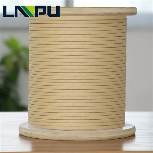
Paper Covered Wire is one of the most traditional and reliable forms of insulated conductor used in high-voltage power transformer windings. By spirally wrapping insulating paper tapes around the conductor surface and forming a stable insulation system after drying and oil impregnation, it is widely used in oil-immersed power transformers at 110kV and above voltage levels.
This article provides a complete engineering reference guide focusing on the technical characteristics, insulation systems, high-voltage application verification, and selection specifications of paper covered wire.
I. Definition and Technical Principle of Paper Covered Wire
1.1 Product Structure
Paper covered wire consists of two parts: a conductor and an insulating paper layer. The conductor is typically made of high-purity electrolytic copper or high-purity electrolytic aluminum, processed through wire drawing and annealing. The insulation layer uses cable paper, telephone paper, or high-density insulating paper, tightly wrapped around the conductor in a spiral overlapping pattern.
1.2 Insulating Paper Material Characteristics
Transformer insulating paper is typically manufactured from sulfate wood pulp (Kraft Paper), a mature material validated through long-term industrial use.
The core value of insulating paper lies in its high compatibility with transformer oil. In dry state, the breakdown voltage of paper covered wire is approximately 15-20kV/2mm. After oil impregnation, the paper fiber pores are filled with transformer oil, forming a paper-oil composite insulation system, with breakdown voltage increasing to 40-55kV/2mm and partial discharge reduced by over 90%.
This is the fundamental reason why paper covered wire is irreplaceable in oil-immersed transformers.
1.3 Wrapping Process
The insulation layer of paper covered wire uses a spiral wrapping process. The overlap rate is typically controlled at 30-50% to ensure no weak points in the insulation. Depending on the voltage level, the number of wrapping layers is typically 2-8. Paper tape thickness is available in multiple specifications: 0.075mm, 0.08mm, 0.12mm, 0.17mm, and 0.20mm.
II. Technical Standards and Model Classification
2.1 International Compliance
The production and testing of paper covered wire follow multiple international standards, including IEC 61072 (Specifications for Paper Covered Winding Wires), IEC 60076 (Power Transformers), NEMA MW 1000 (Magnet Wire Standard), and GB/T 7672 (Chinese National Standard for Paper Covered Wire).
2.2 Model Classification
Paper covered wire can be classified into various models based on conductor material and insulation configuration:
- Type Z (Paper Covered Round Copper Wire): Suitable for 10-35kV distribution transformers
- Type ZL (Paper Covered Round Aluminum Wire): Suitable for 10-35kV distribution transformers, with significant cost advantages
- Type ZZ (Double Paper Covered Wire): Uses double-layer cable paper insulation, suitable for 110-220kV large power transformers
- Type ZC (Composite Insulation Wire): Uses paper + film composite insulation, suitable for 220-500kV ultra-high voltage transformers
2.3 Specification Range
Round wire diameter covers 0.5–6.0mm, flat wire thickness 1.0–5.0mm, and width 3.0–30.0mm, meeting the full range of winding requirements from distribution transformers to ultra-high voltage transformers.
III. Core Performance Parameters
3.1 Performance Changes Before and After Oil Impregnation
The most significant performance characteristic of paper covered wire is the substantial improvement in electrical properties after oil impregnation. The breakdown voltage increases from 15-20kV/2mm in dry state to 40-55kV/2mm after oil impregnation, representing an improvement of 150-200%. Partial discharge decreases from 200-500pC in dry state to 10-50pC after oil impregnation, a reduction of over 90%.
3.2 Comparison with Other Insulated Conductors
In high-voltage applications, the core advantages of paper covered wire lie in oil impregnation compatibility and service life. Compared with enameled wire, paper covered wire is suitable for higher voltage levels (up to 500kV) and has a service life of 30-40 years in oil-immersed transformers. Compared with film-wrapped wire, paper covered wire has lower costs and superior performance in overload capacity and mechanical strength.
3.3 Insulating Paper Type Selection
Different voltage levels correspond to different insulating paper type selections. 10kV and below typically use telephone paper (thickness 0.04-0.05mm); 10-110kV uses cable paper (thickness 0.075-0.12mm); 110-220kV uses high-density insulating paper (thickness 0.075-0.17mm); 220-500kV requires modified paper or paper-film composite insulation.
IV. High Voltage Application Scenarios
4.1 Power Transformer Windings
This is the core application area for paper covered wire. From 10kV distribution transformers to 500kV ultra-high voltage transformers, paper covered wire is the preferred winding insulation solution. The higher the voltage level, the higher the application proportion of paper covered wire. In 220-500kV ultra-high voltage transformers, the application proportion of paper covered wire exceeds 95%.
4.2 Reactor Windings
In high-voltage shunt reactors and series reactors, paper covered wire is also the mainstream choice. Shunt reactors are used for reactive power compensation in ultra-high voltage transmission lines, with voltage levels up to 220-750kV. Series reactors are used to limit short-circuit current and filtering, with voltage levels typically between 35-220kV.
4.3 Instrument Transformer Windings
The high-voltage windings of current transformers (CT) and voltage transformers (PT) also widely use paper covered wire. After oil impregnation, the partial discharge performance of paper covered wire is excellent, meeting the high-precision measurement requirement of ≤5pC partial discharge at 220kV level.
4.4 Special Transformers
In special transformers such as rectifier transformers, electric furnace transformers, traction transformers, and mining transformers, paper covered wire is also a commonly used insulated conductor solution due to its strong overload capacity, high mechanical strength, and safety and reliability.
V. Copper Conductor vs. Aluminum Conductor: Selection in High Voltage Applications
The choice of conductor material is a key consideration in paper covered wire selection.
Copper conductors have a conductivity of 100% IACS, tensile strength of 200-300MPa, and a thermal expansion coefficient that better matches insulating paper, resulting in more stable winding processes. In 500kV ultra-high voltage transformers and 220kV large power transformers, copper conductors are the mainstream configuration.
Aluminum conductors have a conductivity of approximately 61% of copper, a density of only 30% of copper, and a material cost of approximately 1/5 to 1/3 of copper. In 35kV and below distribution transformers and 110kV medium transformers, aluminum conductors are the more cost-effective choice.
5.1 Copper Conductor vs. Aluminum Conductor Performance Comparison
| Comparison Parameter | Paper Covered Copper Wire | Paper Covered Aluminum Wire | Difference Analysis |
|---|---|---|---|
| Conductivity (IACS%) | 100% | 61% | Copper is better; aluminum requires increased cross-section compensation |
| Density (g/cm³) | 8.96 | 2.70 | Aluminum is approximately 70% lighter |
| Tensile Strength (MPa) | 200-300 | 80-120 | Copper is better; winding process is more stable |
| Thermal Expansion Coefficient (×10&supmin;&sup6;/°C) | 16.6 | 23.1 | Copper better matches insulating paper thermal expansion coefficient |
| Material Cost Ratio | 3-5 | 1 | Aluminum has significant cost advantage |
| Applicable Voltage Level | 10-500kV | 10-110kV | Copper has a wider application range |
5.2 Selection Recommendations
| Application Scenario | Recommended Conductor | Reason |
|---|---|---|
| 500kV Ultra-High Voltage Transformers | Copper | High mechanical strength and high reliability requirements |
| 220kV Large Power Transformers | Copper | Mainstream configuration, mature technology |
| 110kV Medium Transformers | Copper/Aluminum Both Acceptable | Select based on cost budget |
| 35kV and Below Distribution Transformers | Aluminum Preferred | Significant cost advantage, mature technology |
| Reactor Windings | Copper | High current density scenarios |
A pragmatic selection strategy is: ultra-high voltage and large transformers should prioritize copper conductors, while medium and low voltage distribution transformers should prioritize aluminum conductors. Many customers, based on the voltage level distribution of their product lines, purchase both copper and aluminum conductors simultaneously, ensuring the reliability of high-end products while effectively controlling overall costs.
VI. Manufacturing Process and Quality Control
6.1 Key Process Flow
The manufacturing of paper covered wire begins with conductor drawing, controlling diameter tolerance within ±0.01mm. Annealing is performed at 350-450°C to ensure elongation ≥ 30%. The paper tape wrapping process is the core of the entire manufacturing process, with overlap rate and tension uniformity directly determining product quality. Drying treatment uses a vacuum process to remove moisture from the paper layers, ensuring moisture content ≤ 0.5%. Final product testing includes breakdown voltage, dimensional, and visual inspection.
6.2 Factory Inspection
Each spool of paper covered wire undergoes full inspection of conductor resistivity, breakdown voltage, dimensions, and appearance before leaving the factory, with a COA report provided. Moisture content is sampled by batch.
6.3 Storage and Transportation
Paper covered wire has high requirements for storage conditions, requiring a temperature of 15-30°C and relative humidity ≤ 60%. Sealed packaging prevents paper layer moisture absorption. During transportation, avoid collision and compression. The shelf life is 12 months from the date of production.