


Paper Covered Wire Electrical Stability in Transformers
Introduction
Paper-covered magnet wire, one of the longest-established and most widely applied insulated conductor forms in power transformers, exhibits electrical stability during long-term transformer operation that directly determines the insulation reliability, operational economy, and service life of the transformer itself. In power transformers rated at 110 kV, 220 kV, 500 kV, and even 1000 kV, paper-covered wire—combined with transformer oil, insulating pressboard, insulating spacers, and insulating end rings—constitutes a complete oil-impregnated paper composite insulation system. The long-term electrical stability of this system is influenced not only by the dielectric properties, geometric structure, and manufacturing processes of the paper-covered wire itself, but also by multiple coupled factors including oil temperature, moisture content, electric field distribution, mechanical stress, oil chemistry, and operational history. This paper focuses specifically on “electrical stability of paper-covered wire for transformers,” systematically addressing the topic from multiple dimensions: the engineering definition of electrical stability; influencing factors; aging mechanisms; test and evaluation methodologies; key technologies; performance variations across different transformer types; and representative failure cases—aiming to provide design engineers, winding manufacturing engineers, insulation technology researchers, and power system operation & maintenance engineers with an engineering-practicable technical framework.
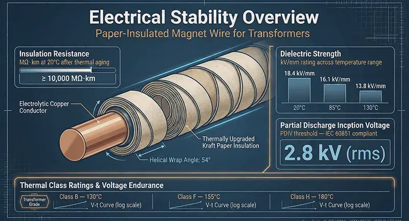
Electrical Stability Overview of Paper-Insulated Magnet Wire for Transformers
Definition and Engineering Implications of Electrical Stability
Electrical stability refers to the ability of an insulating medium to maintain its dielectric properties without irreversible degradation over extended periods under the combined effects of specified operating voltage, thermal stress, mechanical stress, and chemical environment. For paper-covered magnet wire used in transformers, electrical stability encompasses four core dimensions. The first dimension is dielectric strength stability—the ability of breakdown voltage to retain a prescribed safety margin during long-term operation; for new windings, power-frequency breakdown voltage is typically required to be no less than several times the rated voltage. The second dimension is dielectric loss stability—the ability of the dielectric loss factor (tanδ) to remain at a low value and increase only gradually during long-term operation; for new windings, tanδ is generally required to be below 0.005. The third dimension is partial discharge (PD) characteristic stability—the ability to avoid sustained partial discharge under operating voltage; partial discharge inception voltage (PDIV) is typically required to be no less than 1.5 times the operating voltage. The fourth dimension is insulation resistance stability—the ability of volume resistivity and surface resistivity to remain at high values during long-term operation. These four dimensions collectively constitute the evaluation framework for the electrical stability of paper-covered magnet wire.
Operating Environment of Paper-Covered Magnet Wire for Transformers
Paper-covered magnet wire for transformers simultaneously endures electric fields, thermal fields, mechanical stresses, and chemical environments during operation. With respect to electric fields, it is subjected continuously to power-frequency operating voltage superimposed with lightning impulse overvoltage, switching impulse overvoltage, and short-duration over voltages. Regarding thermal fields, oil temperature under normal operation ranges from 85°C to 105°C, while hot-spot temperature may reach 110°C to 120°C; under short-term overload conditions, hot-spot temperature may even exceed 130°C. Concerning mechanical stresses, electromagnetic vibration during operation, short-circuit mechanical shock, thermal expansion/contraction, and transportation vibration collectively impose cumulative mechanical loading. With regard to chemical environment, transformer oil progressively ages during long-term operation, generating aging by-products such as water, acids, and furfural; cellulose paper undergoes degradation reactions at elevated temperatures, releasing water and acidic substances. This quadruple-coupled electro-thermal-mechanical-chemical operating environment imposes stringent requirements on the electrical stability of paper-covered magnet wire.
Relationship Between Electrical Stability and Reliability
Electrical stability constitutes one of the fundamental pillars of transformer reliability. Statistical data indicate that insulation-related failures account for over 70% of power transformer failure cases, with a substantial proportion directly attributable to degradation of the paper–oil insulation system’s electrical stability. Gradual deterioration of electrical stability often manifests initially as measurable parameter changes—e.g., increased tanδ, decreased PDIV, and elevated moisture content; if not promptly identified and mitigated, such degradation may further progress to sustained partial discharge, insulation breakdown, or even catastrophic short-circuit faults. Therefore, electrical stability serves not only as a critical acceptance criterion for new windings but also as a core parameter for condition-based maintenance and lifetime prediction of power transformers.
Critical Factors Affecting Electrical Stability
Long-Term Retention of Dielectric Strength
Long-term retention of dielectric strength represents the most fundamental requirement for electrical stability of paper-covered magnet wire. Dielectric strength is jointly determined by the intrinsic dielectric properties of the paper substrate, number of paper layers, quality of paper–oil compatibility, and uniformity of electric field distribution. During long-term operation, degradation of dielectric strength primarily arises from three mechanisms. First, thermal aging of the paper substrate leads to fiber structure loosening and reduction in degree of polymerization (DP), thereby decreasing dielectric strength; for cable paper operated at 105°C for twenty years, DP may decline from an initial value above 1000 to below 200, resulting in a dielectric strength reduction of 30% to 50%. Second, incomplete impregnation between paper layers creates localized voids that initiate partial discharge under high electric fields, progressively eroding paper layers and reducing dielectric strength. Third, increased moisture content at the oil–paper interface significantly lowers dielectric strength; for every 0.5% increase in moisture content, dielectric strength may decrease by approximately 10% to 15%.
Evolution of Dielectric Loss Factor
Dielectric loss factor tanδ is one of the most sensitive parameters for evaluating electrical stability of the paper–oil insulation system. For new windings, tanδ is typically required to remain below 0.005, exhibiting a smooth monotonic curve versus temperature and voltage. Over long-term operation, tanδ displays a characteristic three-stage evolution profile. Stage I is the stabilization period, during which tanδ remains stable or slightly decreases in early service—reflecting complete impregnation of the oil–paper interface and completion of polarization processes. Stage II is the gradual increase period, wherein tanδ rises progressively with oil–paper aging; its rate of increase correlates closely with temperature, moisture content, and oxygen concentration. Stage III is the accelerated increase period, characterized by a distinct inflection point and rapid rise in tanδ during late-life operation, signaling irreversible insulation deterioration. The rate of tanδ increase follows the Arrhenius relationship: for every 8°C to 10°C rise in temperature, the tanδ increase rate approximately doubles.
Stability of Partial Discharge Inception Voltage
Partial discharge inception voltage (PDIV) and partial discharge extinction voltage (PDEV) constitute another critical parameter set reflecting the electrical stability of paper-covered magnet wire. For new windings, PDIV is typically required to exceed 1.5 times the operating voltage, while PDEV is generally slightly lower than PDIV; the difference between them reflects the “hysteresis effect” of discharge. During long-term operation, PDIV decline is driven primarily by three factors: (i) expansion or formation of new internal voids within the insulation, lowering the threshold for void discharge; (ii) aggravated electric field distortion at the conductor–insulation interface, elevating local electric field strength; and (iii) surface moisture absorption or contamination of paper layers, reducing surface discharge inception voltage. A rapid decline in PDIV often indicates the presence of non-negligible internal defects and serves as a key early-warning signal for life prediction.
Evolution of Insulation Resistance and Volume Resistivity
Insulation resistance serves as a comprehensive indicator of overall insulation performance of paper-covered winding wire, whereas volume resistivity represents an intrinsic material property reflecting inherent insulating capability. For new windings, insulation resistance is typically required to reach hundreds to thousands of megaohms. Over long-term operation, insulation resistance exhibits a characteristic exponential decay behavior, with decay rate significantly influenced by temperature, moisture content, and electric field strength. For every 10°C rise in oil temperature, insulation resistance approximately halves; for every 0.5% increase in moisture content, insulation resistance declines by approximately 30% to 50%. A steady, predictable decay in insulation resistance generally corresponds to normal aging; however, an unexpected rapid decline often signals either localized breakdown or severe moisture ingress within the insulation.
Aging Mechanisms and Electrical Stability Degradation
Thermal Aging Mechanism
Thermal aging is the dominant degradation mechanism for cellulose paper insulation. Cellulose is a natural high-molecular polymer composed of glucose units linked by β-1,4-glycosidic bonds; its degradation follows a chain scission mechanism. Within the temperature range of 100°C to 130°C, hydrolysis of glycosidic bonds in the cellulose molecular chain occurs, causing the degree of polymerization (DP) to gradually decline from an initial value exceeding 1000. The direct consequence of DP reduction is decreased mechanical strength and structural loosening of the cellulose fibers, leading to deterioration of electrical stability—including reduced dielectric strength, increased tanδ, and elevated moisture content. Classical lifetime estimation for thermal aging follows the Montsinger rule: for every 8°C to 10°C increase in temperature, insulation lifetime is approximately halved.
Electrical Aging Mechanism
Electrical aging results from prolonged partial discharge (PD) activity. In insulation structures containing voids, the breakdown field strength of the void is lower than that of the surrounding insulating medium; thus, PD initiates first within the void under operating voltage. High-energy electrons, ions, ultraviolet radiation, and reactive chemical species generated by PD cause continuous physical and chemical erosion of the paper-based material, progressively forming PD channels, tree-like discharge traces, or carbonized paths within the paper layers—ultimately resulting in irreversible reduction of dielectric strength. The electrical aging rate correlates closely with PD magnitude, PD repetition frequency, and PD duration. Higher electric field strength leads to exponential acceleration of the electrical aging rate.
Chemical Aging Mechanism
Chemical aging primarily refers to interfacial chemical reactions occurring at the oil–paper interface. Transformer oil, under long-term thermal and oxidative stress, generates aging by-products including organic acids, water, alcohols, aldehydes, and ketones; concurrently, cellulose paper releases water, furfural, and various organic acids during its degradation process. These aging by-products collectively establish an acidic environment at the oil–paper interface, further catalyzing cellulose degradation and establishing a typical autocatalytic aging cycle. Furfural concentration in oil serves as a key indicator of cellulose degradation extent; furfural levels exceeding 1 mg/L to 2 mg/L typically signal entry into an accelerated aging phase.
Mechanical Aging Mechanism
Mechanical aging arises primarily from short-circuit electromagnetic forces, vibration, and cumulative thermal expansion/contraction effects. The enormous electromagnetic forces generated by short-circuit currents can instantaneously inflict mechanical damage on winding insulation—causing paper layer misalignment, deformation of paper-covered conductors, or insulation breach. Prolonged electromagnetic vibration induces loosening of spacers and pressboards within the insulation structure, compromising overall insulation compactness. Thermal expansion/contraction induces alternating shear stresses at the interface between insulation layers and conductors; over time, this may generate microcracks or interfacial delamination. Although less severe than thermal or electrical aging, mechanical aging often acts as the triggering factor for sudden insulation failure.
Multi-Factor Synergistic Aging
In actual transformer operation, thermal, electrical, mechanical, and chemical aging mechanisms do not occur independently but instead interact to form a highly coupled synergistic aging process. Elevated temperature accelerates electrical aging, as higher temperatures lower the PD inception voltage; regions of electric field concentration frequently coincide with regions of thermal field concentration; mechanically damaged sites tend to absorb moisture, inducing localized dampness; and chemical aging by-products alter local electric field distribution. Synergistic aging causes insulation lifetime to fall significantly below the simple arithmetic sum of lifetimes predicted under individual aging factors alone. Therefore, multi-factor accelerated aging models must be employed for accurate insulation lifetime prediction.
Electrical Stability Testing Methods and Evaluation System
Dielectric Breakdown Testing
Dielectric breakdown testing is the most direct method for evaluating the dielectric strength of paper-covered magnet wire. Commonly referenced standards include IEC 60851, ASTM D149, and GB/T 4074. Testing is typically performed using a stepwise voltage ramp: the initial voltage is set at 50% of the rated breakdown voltage, then increased uniformly at a rate of 500 V/s to 1000 V/s until breakdown occurs. For new paper-covered wire, the breakdown voltage is generally required to reach the 8 kV to 12 kV range; power-frequency breakdown voltage correlates closely with the number of paper layers, base paper material, and impregnation quality. Weibull distribution analysis of multiple breakdown data yields characteristic breakdown voltage and dispersion parameters—key statistical metrics for assessing insulation reliability.
Dielectric Loss and Temperature/Voltage Characteristics
Dielectric loss testing is a core method for evaluating the electrical stability of paper-covered magnet wire. Tests are typically conducted at power frequency, measuring the variation of tanδ versus applied voltage (0.2 U_N, 0.4 U_N, 0.6 U_N, 0.8 U_N, 1.0 U_N) and temperature (30°C, 60°C, 90°C, 120°C). A well-performing paper-oil insulation system exhibits low, smooth, and monotonically increasing tanδ–V and tanδ–T curves. “Knee points” or “humps” on these curves often indicate internal defects such as voids, excessive moisture content, or partial discharge activity.
Partial Discharge Inception Voltage Testing
Partial discharge (PD) testing is a critical method for evaluating the discharge stability of paper-covered magnet wire. Testing follows IEC 61262: voltage is ramped up incrementally under specified sensitivity until stable PD signals appear, recording the Partial Discharge Inception Voltage (PDIV); voltage is then ramped down incrementally until PD extinguishes, recording the Partial Discharge Extinction Voltage (PDEV). High-quality paper-oil insulation systems exhibit PDIV > 1.5 U_N and a small difference between PDEV and PDIV. Phase-Resolved Partial Discharge (PRPD) patterns serve to identify discharge types—including internal discharge, surface discharge, and corona discharge—and constitute an essential tool for failure diagnostics.
Accelerated Aging Tests and Lifetime Prediction
Accelerated aging tests employ elevated stress factors—such as temperature, voltage, or frequency—to obtain long-term insulation aging data within shortened test durations. Classical accelerated aging models include the Arrhenius model, Inverse Power model, and Simoni model. Lifetime predictions extrapolated from accelerated aging data require validation and correction using field operational data. IEEE 638 provides specific methodologies for transformer insulation aging assessment.
Dissolved Gas Analysis
Dissolved Gas Analysis (DGA) is a mature technique for evaluating transformer insulation condition. By quantifying concentrations and ratios of dissolved gases—including H₂, CH₄, C₂H₆, C₂H₄, C₂H₂, CO, and CO₂—in insulating oil, and applying diagnostic criteria such as the Duval triangle and Roger ratios, DGA enables identification of internal insulation faults including partial discharge, thermal overheating, and arcing. Correlative analysis between DGA data and electrical stability parameters represents a key research direction in transformer condition assessment.
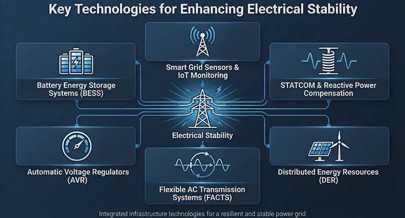
Key Technologies for Enhancing Electrical Stability
Paper-Based Material Optimization
The intrinsic properties of paper-based materials constitute the foundation of electrical stability. Thermally upgraded kraft paper—achieved through the addition of amine-based stabilizers or chemical modification—can elevate the long-term operating temperature from 105°C to above 130°C, significantly retarding the thermal aging rate. Aramid paper supports long-term operation up to 220°C and is primarily employed in specialized high-temperature transformers. Nano-modified cellulose paper, incorporating fillers such as nano-SiO₂, nano-Al₂O₃, or nano-TiO₂, markedly enhances dielectric strength and mechanical strength. The composite structure of polyimide film and aramid paper combines the high dielectric strength of film with the flexibility of paper, representing a critical material choice for premium oil-immersed windings.
Impregnation Process Optimization
Vacuum Pressure Impregnation (VPI) is a key process for enhancing the electrical stability of the paper–oil insulation system. Critical process parameters ensuring thorough void filling within the insulation include high vacuum level (typically below 100 Pa), elevated oil temperature (80°C to 100°C), high pressure (0.5 MPa to 1.0 MPa), and appropriate impregnation duration. Post-impregnation drying and degassing treatments are equally vital for long-term stability; oil moisture content must be controlled below 20 ppm.
Oil–Paper Synergistic Control
Transformer oil quality exerts a decisive influence on the electrical stability of the paper–oil insulation system. Oil purification technologies—including vacuum filtration, adsorbent filtration, and molecular sieve dehydration—effectively reduce moisture content, gas content, and acidic substances in the oil. Balanced moisture control between oil and paper is essential for long-term stable operation; paper moisture content must be maintained below 0.5%. Antioxidant additives effectively retard oil aging and suppress generation of acidic by-products.
Multi-Layer Paper Insulation Structure Optimization
Design of multi-layer paper insulation structures significantly impacts electrical stability. Rational configuration of the number of paper layers, individual paper thickness, oil duct width, and insulation end-ring geometry enables uniform electric field distribution and suppresses partial discharge triggered by electric field concentration. Finite element electric field simulation has become an indispensable tool in insulation structure design.
Novel Monitoring Technologies
Online monitoring technologies enable real-time assessment of electrical stability. Online partial discharge (PD) monitoring permits real-time capture of PD signals and identification of PD types; online dielectric loss monitoring continuously tracks tanδ trends; online Dissolved Gas Analysis (DGA) provides real-time detection of dissolved gas concentration changes in oil. Integrated with big data and artificial intelligence algorithms, multi-parameter fusion–based insulation condition assessment and lifetime prediction models have emerged as a prominent research focus.
Electrical Stability Characteristics Across Transformer Types
Distribution Transformers
Distribution transformers are typically rated from 10 kV to 35 kV, with capacities ranging from several hundred kVA to several MVA. Windings commonly adopt cylindrical or foil-type configurations. Operating environments for distribution transformers are relatively mild, characterized by limited temperature fluctuations and low mechanical stress; thus, their electrical stability is predominantly governed by thermal aging. The typical design life is 25–30 years, while in actual service, the electrical stability of most distribution transformers enters a pronounced degradation phase between 20 and 25 years.
Power Transformers
Power transformers are typically rated from 110 kV to 500 kV, with capacities ranging from several tens of MVA to several hundreds of MVA. Windings commonly adopt disc-type, continuous-type, or helical configurations. Power transformers endure high electric, thermal, and mechanical stresses acting synergistically; consequently, their electrical stability is dominated by multi-factor synergistic aging. The typical design life is 30–40 years, though actual service life is significantly influenced by operating conditions.
Large-Scale Power Transformers
Large-scale power transformers refer to ultra-high-voltage (UHV) transformers rated from 500 kV to 1000 kV. Their insulation structures are highly complex, featuring numerous paper layers, high electric field strength, and stringent mechanical requirements. The electrical stability of UHV transformers imposes extremely high demands on insulation materials, manufacturing processes, and operation & maintenance practices. The typical design life is 40–50 years.
Special-Purpose Transformers
Special-purpose transformers include electric furnace transformers, rectifier transformers, and traction transformers, each operating under distinctive environmental conditions. Electric furnace transformers withstand frequent short-circuit impulses and current surges, with their electrical stability significantly affected by mechanical aging. Rectifier transformers endure harmonic voltages and harmonic currents, with their electrical stability significantly affected by electrical aging. Traction transformers experience severe load fluctuations and vibration, with their electrical stability dominated by multi-factor synergistic aging.
Correlation Between Typical Failure Cases and Electrical Stability
PD-Initiated Breakdown
After 18 years of operation, a 220 kV power transformer exhibited abnormal growth in oil DGA data; DGA revealed a marked increase in C₂H₂ content. Integrated with online partial discharge (PD) monitoring data, persistent PD was identified at the high-voltage winding ends. During outage inspection, distinct tree-like PD traces and localized carbonization of the insulation paper layers were observed at the winding ends. Analysis indicated that internal voids within the insulation expanded over long-term operation, resulting in a reduction of PDIV and eventual insulation breakdown. This case underscores the critical importance of continuous PDIV monitoring for preventing major insulation failures.
Dielectric Loss Increase Leading to Overheating
After 22 years of operation, an 110 kV power transformer exhibited a continuous rise in tanδ as detected by online monitoring, with an annual average growth rate of 8%—significantly exceeding normal aging levels. During outage inspection, moisture content in the oil reached 35 ppm, markedly elevated; moisture content in the paper reached 1.2%, far exceeding the standard requirement of 0.5%. Analysis indicated that aging of sealing components permitted moisture ingress into the transformer, triggering rapid tanδ escalation. This case highlights the pivotal role of coordinated moisture control in both oil and paper for electrical stability.
Moisture Overload–Induced Stability Degradation
A 35 kV distribution transformer experienced insulation breakdown after 12 years of operation. Post-failure testing revealed oil moisture content at 50 ppm and paper moisture content at 1.5%. The transformer operated in a humid environment, and the breather’s silica gel had not been replaced timely, permitting continuous moisture ingress. Analysis confirmed that moisture overload was the primary cause of the transformer’s abrupt decline in electrical stability and ultimate failure. This case emphasizes the critical necessity of regular breather maintenance for transformers operating in humid environments.
Cumulative Effect of Short-Circuit Impulses
A 500 kV power transformer sustained 12 near-zone short-circuit impulses over its 25-year service life, with the most recent short-circuit current reaching 12 times the rated current. Post-accident inspection revealed multiple locations of insulation paper layer misalignment and deformation of paper-covered conductors; in certain areas, delamination occurred between the paper layer and conductor. Analysis indicated that mechanical damage compromised the integrity of the insulation structure, exacerbating electric field distortion and ultimately causing insulation failure. This case illustrates the long-term impact of cumulative short-circuit impulse effects on electrical stability.
Conclusion
The electrical stability of paper-covered magnet wire for transformers is the core determinant of transformer insulation reliability, operational economy, and service life. The concept of electrical stability encompasses four key dimensions: dielectric strength, dielectric loss (tanδ), partial discharge (PD), and insulation resistance. Its degradation is jointly governed by thermal aging, electrical aging, chemical aging, mechanical aging, and multi-factor synergistic aging. The primary testing and evaluation framework for electrical stability comprises dielectric breakdown testing, dielectric loss (tanδ) testing, partial discharge (PD) testing, accelerated aging tests, and dissolved gas analysis (DGA) in insulating oil. Key technical pathways to enhance electrical stability include paper substrate material optimization, impregnation process optimization, oil-paper synergistic control, multilayer paper insulation structure optimization, and novel monitoring technologies. Electrical stability characteristics vary significantly among transformer types, necessitating application-specific design, operation, and maintenance strategies. With the continuous advancement of novel paper-based materials, automated manufacturing processes, and intelligent monitoring technologies, the electrical stability of paper-covered magnet wire for transformers will enter a new phase of enhancement, providing a more robust foundation for highly reliable power transformer operation.