
Paper Covered Wire Design Considerations for Engineers
Introduction
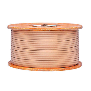
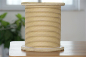
As a core winding material for power transformers and motors, the design and selection of paper covered wire directly affects the electrical performance, mechanical reliability, and service life of the equipment. For electrical engineers, mastering the core elements of paper covered wire design is crucial to ensuring high-quality manufacturing of transformers and motors.
This article, aimed at engineers engaged in transformer and motor design and manufacturing, systematically introduces the basic principles of paper covered wire design, technical parameter calculation methods, selection points, and common design problems, providing comprehensive technical reference for engineering practice.
Basic Principles of Paper Covered Wire Design
Design Objectives
Paper covered wire design needs to comprehensively consider the following core objectives:
- Meeting Electrical Performance Requirements: Ensuring that insulation strength, dielectric loss, and other indicators meet standard requirements is the primary design objective. Failure to meet electrical performance standards will directly lead to equipment failing factory testing or insulation failures after commissioning.
- Ensuring Reliability: The design should consider long-term operational stability, with sufficient design margins for all parameters to ensure safe operation within the expected lifespan. Reliability design is the foundation for ensuring a service life of twenty years or more.
- Economic Efficiency: Optimize material selection and process design to achieve reasonable cost control while meeting performance requirements. Over-design will lead to unnecessary cost increases, while under-design will bring quality risks.
- Process Feasibility: The design should facilitate manufacturing and quality control, avoiding overly complex process requirements. The design needs to match manufacturing capabilities to ensure consistency in mass production.
Design Basis
The design basis for paper-insulated conductors includes:
- Standards and Specifications: IEC 60250, GB/T 7674, NEMA MW 1000, and other domestic and international standards specify the basic parameters, test methods, and acceptance criteria for paper-insulated conductors.
- Equipment Technical Requirements: Equipment-specific parameters such as voltage level, rated capacity, operating environment, and insulation class are input conditions for the design.
- Insulation Coordination Principles: The system design of conductor insulation and oil-immersed insulation needs to be considered holistically. Paper-insulated conductors are not isolated components, but rather part of the entire insulation system.
Design Process
The typical design process for paper-insulated conductors is as follows:
- Determine the equipment’s technical parameters, including voltage level, rated capacity, insulation class, operating ambient temperature, altitude, etc.
- Determine the insulation thickness based on the voltage level, referring to standard recommendations and empirical data.
- Calculate the conductor cross-section and current density, calculating the required conductor cross-sectional area based on the rated current and allowable current density.
- Perform thermal performance verification, calculating the winding temperature rise to confirm that it does not exceed the allowable operating temperature.
- Perform mechanical performance verification, calculating the short-circuit electrodynamic force to confirm that the short-circuit withstand capability meets the requirements.
- Optimize the design through comparison with standard specifications and test data.
Technical Parameters and Calculations
Insulation Thickness Design
Insulation thickness is one of the most crucial parameters in paper-insulated conductor design, directly determining insulation performance. The design of insulation thickness needs to consider the following factors:
- Voltage Rating: The insulation thickness must meet the dielectric strength requirements of the corresponding voltage level. High voltage levels require thicker and more uniform insulation.
- Safety Margin: The design breakdown voltage should be no less than 3-5 times the rated voltage to ensure sufficient safety margin.
- Electric Field Distribution: The electric field concentration effect at the ends needs to be considered, and the end insulation design should be appropriately strengthened.
| Voltage Rating | Number of Paper Layers | Insulation Thickness |
|---|---|---|
| 6-10kV | 2-3 layers | 0.45-0.75mm |
| 35kV | 4-5 layers | 1.0-1.5mm |
| 66-110kV | 6-8 layers | 2.0-3.0mm |
| 220kV and above | 10 layers and above | 3.0mm and above |
Conductor Cross-Section Design
The design of the conductor cross-section is related to the load capacity and temperature rise of the transformer.
Where: I is the rated current (A); J is the current density (A/mm²); K is the window fill factor.
| Application | Current Density (A/mm²) | Notes |
|---|---|---|
| Oil-immersed transformer | 2-4 | Natural cooling: lower values; Forced oil circulation: higher values |
| Dry-type transformer | 1.5-3 | Consider heat dissipation conditions and duty cycle |
| Motors | 3-5 | Selected based on insulation class and duty cycle |
Insulation Resistance Calculation
Insulation resistance is an important parameter for measuring insulation performance. Insulation resistance is directly proportional to insulation thickness and the volume resistivity of the insulating material. During design, it is necessary to ensure that the insulation resistance meets the minimum requirements specified in the standard, typically not less than 100 MΩ. For high-voltage equipment, the insulation resistance requirements are even higher.
Insulation Class and Heat Resistance Design
Insulation Class Classification
The insulation class of paper-insulated conductors is classified according to heat resistance temperature. Different classes correspond to different material systems:
| Insulation Class | Maximum Operating Temperature | Typical Application |
|---|---|---|
| Class A | 105°C | Ordinary oil-immersed transformer |
| Class B | 130°C | Heat-resistant oil-immersed transformer |
| Class F | 155°C | High load or high temperature environment |
| Class H | 180°C | Extreme environment or special requirements |
Temperature Verification
During the design process, the winding temperature rise needs to be verified to ensure that it does not exceed the allowable operating temperature of the insulation class:
Where θ_ambient is the ambient temperature, and Δθ_winding is the winding temperature rise.
Key Points of Heat Resistance Design
- Selection of High-Grade Insulation Paper: F-grade and H-grade insulation paper are made of heat-resistant fiber materials and can operate stably at higher temperatures.
- Optimization of Heat Dissipation Structure: Setting up oil channels or air-cooling channels improves heat dissipation conditions and reduces operating temperature.
- Control of Load Rate: Avoiding long-term full-load operation can effectively extend insulation life. Controlling the load rate below 80% can significantly extend equipment lifespan.
Mechanical Performance Design
Short-Circuit Capability Design
The short-circuit electrodynamic force is the maximum mechanical stress borne by the winding, which must be fully considered in the design:
Where: I is the short-circuit current; L is the winding height; D is the winding diameter; k is a coefficient. The short-circuit electrodynamic force is proportional to the square of the short-circuit current, and in the most severe cases, it can reach thousands of times that of the rated load.
Design Considerations: Ensure sufficient mechanical strength support; arrange support bars reasonably; set up effective clamping devices to prevent winding loosening.
Vibration Resistance Design
For equipment operating in a vibrating environment, such as wind turbines, the impact of vibration loads should be fully considered:
- Use a dense wrapping structure to enhance overall integrity
- Increase end supports to improve overall stiffness
- Select material combinations with better vibration resistance
Bending Radius Control
The bending radius of the paper-insulated conductor affects the insulation integrity:
Process Control: Avoid creases or cracks at small radius positions. A special mold should be used during winding to ensure the bending radius.
Design Considerations for Special Applications
High-Altitude Applications
At altitudes exceeding 1000m, air insulation strength decreases, requiring an appropriate increase in insulation thickness or other compensatory measures:
High Humidity Environments
Humid environments affect insulation performance:
- Strengthen sealing design to prevent moisture intrusion
- Select moisture-resistant insulation structures
- Increase insulation margin to mitigate the adverse effects of humidity
Salt Spray Corrosion Environments
Salt spray corrosion needs to be a primary consideration for coastal or offshore applications:
- Strengthen insulation sealing
- Use corrosion-resistant materials
- Add protective coatings
Quality Control and Testing
Incoming Material Inspection
Paper-insulated wires undergo strict inspection upon arrival at the factory:
- Appearance Inspection: The paper layer should be uniform, without damage, delamination, or stains.
- Dimensional Measurement: Key dimensions such as conductor diameter, insulation thickness, and width must meet technical requirements.
- Electrical Performance: Resistivity testing confirms that conductivity meets requirements.
Winding Process Control
The process control of the winding process is crucial to the final product quality:
- Process Parameter Control: Parameters such as tension, speed, and winding angle must be precisely controlled.
- Process Inspection: Regularly sample insulation thickness and overlap rate to ensure process stability.
Finished Product Testing
Finished product testing is the final means of verifying the rationality of the design:
- Electrical Testing: Insulation resistance, withstand voltage, and partial discharge tests are mandatory tests before shipment.
- Performance Verification: Thermal aging test and mechanical strength test are used to verify whether the design meets the life requirements.
Common Design Problems and Solutions
Insufficient Insulation Thickness
Problem: Failure to pass the withstand voltage test, excessive partial discharge.
Cause: Insufficient design margin or deviation in raw material thickness.
Solutions: Increase insulation thickness or improve insulation class. A new electric field analysis may be necessary.
Excessive Temperature Rise
Problem: Operating temperature exceeds the design value.
Cause: Excessive current density, poor heat dissipation, overload.
Solutions: Increase conductor cross-section to reduce current density; improve heat dissipation conditions; control the load to not exceed the design value.
Excessive Partial Discharge
Problem: Partial discharge exceeds the standard limit.
Cause: Internal defects in insulation, bubbles, poor paper layer overlap.
Solutions: Improve the impregnation process to ensure vacuum levels; strengthen process inspection; select high-quality material suppliers.
Design Selection Quick Reference Table
Transformer Applications
| Application | Recommended Wire | Insulation Class |
|---|---|---|
| Power Distribution Transformer | Paper-Sheathed Round Wire | Class A/F |
| Power Transformer | Paper-Sheathed Flat/Round Wire | Class B/F |
| High Voltage Transformer | Paper-Sheathed Flat + Enameled Paper | Class F/H |
| Special Transformer | Designed per Requirements | Per Requirements |
Motor Applications
| Application | Recommended Wire | Insulation Class |
|---|---|---|
| Industrial Motors | Paper-Sheathed Round Wire | Class B/F |
| Crane Motors | Paper-Sheathed Round Wire | Class F |
| Wind Turbines | Paper-Sheathed Flat Wire | Class F/H |
| Traction Motors | Paper-Sheathed Flat Wire | Class H |
Conclusion
The design of paper-sheathed wire is a comprehensive technical task, requiring electrical engineers to fully understand material properties, master design calculation methods, and combine them with engineering practice experience. The design principles, calculation methods, and selection points introduced in this article can provide engineers with practical technical references. In actual design, these principles should be flexibly applied according to the specific equipment’s technical requirements and operating environment to ensure design quality.
Contact Information
Email: office@cnlpzz.com
WhatsApp: 0086-19337889070
This article was compiled by Zhengzhou LP Industry Co., Ltd., which has focused on the research and manufacturing of electrical magnet wire and special conductors for thirty years.