

Special Requirements of Paper Covered Wire in Substation Service
A substation is a node where power grid energy is aggregated and distributed. The main transformer, circuit breaker, disconnecting switch, current transformer, voltage transformer, grounding transformer, and station service transformer’s winding all rely on some form of insulated wire to complete energy conversion. The role of paper covered wire here is more complex than in conventional power distribution transformers.
A fact that is easily overlooked is that substation paper covered wire is not directly exposed to the air most of the time. The high-voltage winding of a 110 kV outdoor oil-immersed main transformer is completely submerged in the insulating oil tank. What is actually exposed to the outdoor environment are the external insulation structure, lead clamps, and part of the secondary winding. Therefore, the proposition of “using paper covered wire in the substation” actually spans three very different operating conditions—the enclosed high-temperature environment inside the tank, the condensation and pollution environment outside the tank, and the completely exposed environment in dry or composite equipment.
The requirements for insulation materials differ among these three operating conditions. The tank requires high compatibility with mineral oil, low dielectric loss, and stable thermal aging; the tank exterior requires moisture resistance, pollution resistance, and ultraviolet resistance; while dry-type equipment requires high thermal class and flame retardancy. This divergence in operating conditions dictates that paper covered wire in substations is never a matter of “one specification for everything,” but rather requires matching according to equipment type.
Another practical constraint, often written into technical solutions but rarely discussed, is the extremely short maintenance window of substations. Main transformer outages for maintenance often require dispatch schedule applications, with approval cycles taking weeks or even months. Under such constraints, the redundancy of winding insulation design directly determines the probability of unplanned outages. A windage invisible within the tank, once it causes an inter-turn short circuit, means months of downtime for factory repairs. This practical pressure has directly driven the widespread adoption of high-thermal-class paper-based materials and longer design lifespans in substation main transformers.
Where Paper Covered Wire Is Used in Substation Equipment
The main transformer winding uses the most paper covered wire in the substation. It is commonly used in the high-voltage winding of main transformers of 66 kV and above, and its application rate exceeds 95% in ultra-high voltage main transformers of 330 kV to 750 kV. These windings are mostly cylindrical, segmented, or disc-shaped, with conductors primarily rectangular flat wires, cross-sectional widths from 30 mm to 80 mm and thicknesses from 8 mm to 20 mm. The number of insulating paper layers, overlap ratio, and interlayer insulation structure must correspond to the winding voltage class.
Voltage regulation winding and on-load tap changer winding represent the second high-frequency application area. Tap changing involves frequent current switching and temperature cycling, making the thermal aging and arc resistance of the paper covered wire more critical than in static winding.
Current transformers and voltage transformers constitute the third application area. Outdoor dry-type current transformers, operating in voltage classes from 33 kV to 230 kV, typically employ a single-layer tightly wound winding system, with insulating paper as the direct insulation medium. This instrument transformer differs from traditional oil-immersed structures because it is entirely encapsulated in solid insulation. Here the paper covered wire serves mainly to provide high-density winding support and stable dielectric isolation, rather than fulfilling independent dielectric withstand capabilities. Paper covered wire winding is also used in voltage transformers of 35 kV and above.
Grounding transformers, arc suppression coils, and substation transformers are easily overlooked but real application scenarios. Arc suppression coils must operate under high voltage for extended periods with good tuning characteristics; their winding insulation covering scheme is directly related to paper covered wire technology. Although substation transformers have smaller capacities, they supply the substation’s own DC system, lighting, and maintenance, requiring extremely high reliability. Their design often directly follows the insulation technology approach of oil-immersed main transformers.
The internal electromagnetic operating mechanism of a switchgear, the trip coil, and the current transformer in certain circuit breaker models also utilize small-scale paper covered wires. These applications often have more stringent requirements for conductor outer diameter and bending performance than the main transformer winding.
Outdoor Substation Environment and Insulation Challenges
The destructive power of the substation outdoors comes mainly from four directions.
Condensation is the primary threat. Diurnal temperature variations, seasonal changes, and the cooling process after equipment shutdown all contribute to the formation of a condensation film on the paper covered wire surface and during inter-turns. The fiber paper is highly hygroscopic; once moisture penetrates the insulation layer, it directly leads to an increase in the dissipation factor, a decrease in the partial discharge initiation voltage, and accelerated insulation aging. In coastal or high-humidity areas, this problem can significantly shorten the actual maintenance cycle of equipment.
Pollution and salt spray pose a second challenge. Industrial pollution particles and sea salt deposits on insulation surfaces form a conductive film, reducing surface insulation resistance under humid conditions. This places additional demands on the creepage distance between the winding ends and lead sections, and has driven the evolution of overall protection schemes for transformer external insulation design—the application of synthetic insulation bushing in coastal and high-pollution areas is a direct result of this pressure.
Ultraviolet (UTI) and temperature cycling pose a third challenge. Although the insulation body is typically not exposed to direct sunlight, the outer surfaces of outdoor equipment and partially exposed lead sections are subjected to UTI aging over time. For fiber-based insulation systems, UTI accelerates molecular chain breakage, causing the mechanical strength of the paper-based material to decrease over time.
Mechanical vibration and short circuit impulse constitute the fourth challenge. The substation equipment endures combined loads from grid faults, switching operations, and foundation fretting. Under short-circuit conditions, the winding experiences enormous electromagnetic forces generated by currents tens of times the rated current, and the insulation layer must remain intact under dynamic stress. The fatigue behavior of the paper-based material under long-term vibration in the environment is a key characteristic that distinguishes the substation’s operating conditions from those of indoor equipment.
Insulating Paper Material System and Voltage Class Matching
The choice of paper-based material for the substation paper covered wire is strongly related to the equipment voltage class, insulation structure type, and operating environment.
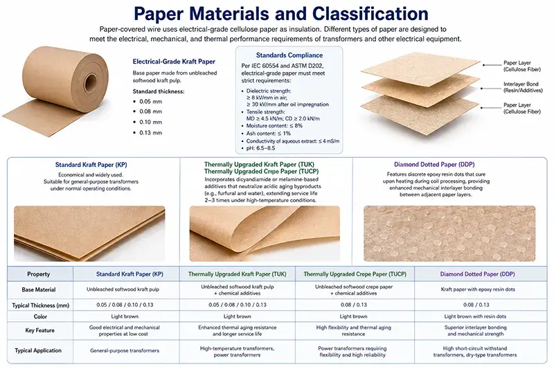
Kraft paper is the most basic fiber-based material, made from unbleached sulfate wood pulp. It has high mechanical strength, good impregnation properties, and low cost. Its thermal class is typically between 105 °C and 120 °C, and it is widely used in oil-immersed transformer winding. Thermal upgrade kraft paper is chemically modified by adding thermal stabilizers, raising its thermal class to above 130 °C, thus maintaining stable electrical and mechanical properties at higher temperatures.
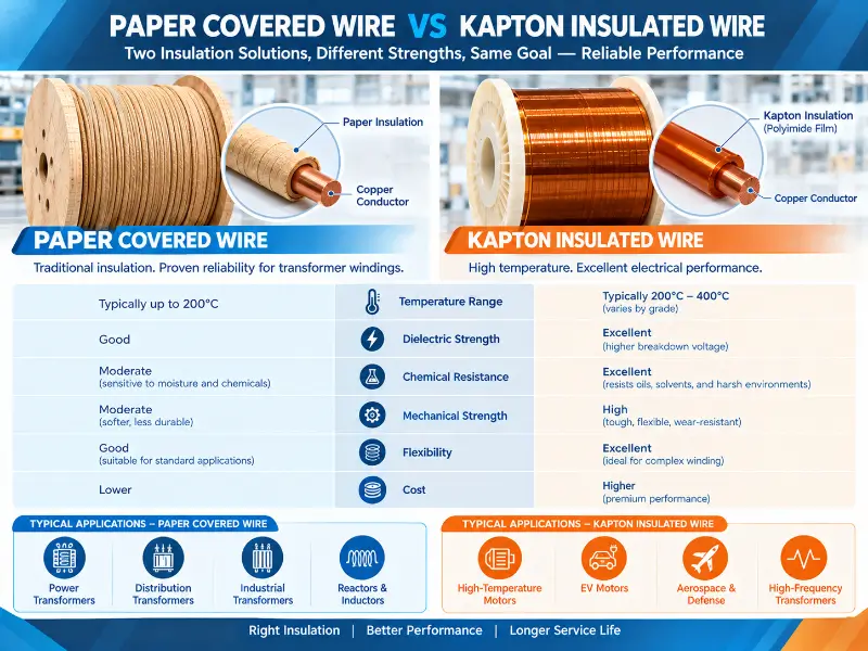
In high-voltage substations, aramid paper is more commonly used. Aromatic polyamide fiber paper possesses excellent heat resistance, mechanical strength, and dielectric performance, with a thermal class exceeding 220 °C. It provides reliable insulation protection in dry-type transformers, oil-immersed high-temperature transformers, and traction transformers. In ANSI/NEMA MW 1000-2018, MW 60-A and MW 60-C specify aromatic polyamide paper covered rectangular magnet wire for aluminum conductors and copper conductors, respectively. MW 61-A and MW 61-C provide corresponding round wire specifications, all with a thermal class of 240 °C. This serves as the direct basis for the design and acceptance of high-temperature substation main transformers.
The thickness of the insulating paper is distributed in steps according to the voltage class. For voltage classes of 10 kV and below, thin insulating paper with a thickness of 0.04 mm to 0.05 mm is typically used for communication applications; for 10 kV to 110 kV, cable paper with a thickness of 0.075 mm to 0.12 mm is used; for 110 kV to 220 kV, high-density insulating paper with a thickness of 0.075 mm to 0.17 mm is used; and for 220 kV to 500 kV, modified paper or a paper-film composite insulation structure is required. The minimum number of layers for the paper tape is usually two. The overlap ratio, number of layers, materials, and packaging method must be clearly agreed upon in the technical specification between the supplier and the buyer.
A common misconception exists regarding the interpretation of “thermal class”: pure kraft paper insulation corresponds to Class A (105 °C) as defined in IEC 60085, but in oil-immersed systems, after impregnation (using oil), the operating class can be upgraded to Class B (130 °C). For high-temperature scenarios requiring operation between 155 °C and 220 °C, paper is used as a composite insulation substrate in conjunction with mica tape or aramid tape—the paper layer provides dielectric support and structural shaping, while high-temperature resistance is provided by the high-performance tape. This hybrid structure is a practical approach for high-temperature main transformer insulation design.
Paper Covered Wire Impregnation Compatibility and Dry-Type Equipment Differences
The core of the insulation system construction for oil-immersed substation main transformers lies in the impregnation process. Vacuum pressure impregnation effectively removes moisture and gases from the paper-based material and enamel coating, allowing the insulating oil to fully penetrate the insulation layer. Excess impregnated oil is drained back into the tank under gravity, ensuring no air bubbles remain between the insulating paper layers, at the inter-turn points, or between the paper and the conductor. This void-free impregnation state is the foundation for the long-term reliable operation of the paper covered wire within the tank.
Dry substation equipment follows a completely different path from composite insulation equipment. This type of equipment uses solid insulation media such as epoxy resin, polyester resin, or silicone rubber instead of transformer oil, and winding typically employs vacuum pressure impregnation or casting processes. The paper tape layer of the paper covered wire provides channels for resin penetration during this process, allowing the resin to fully fill the void inside the winding, forming a void-free insulation structure. Aramid paper has significant advantages in these applications—its compatibility with epoxy resin, dielectric stability, and mechanical toughness have been proven through long-term engineering, and it also possesses good flame retardancy, enabling slow fire spread in fault conditions.
The emergence of gas insulation transformers has introduced new technological variables to substation paper covered wire. In these devices, the winding insulation needs to withstand the chemical environment of SF₆ or mixed gas, while maintaining a high continuous winding length to control partial discharge levels. The application of paper covered wire in gas insulation transformers is still in its developmental stage; its covering structure, gas tightness requirements, and compatibility with gas decomposition products are current research hotspots.
Key performance indicators and acceptance testing
The acceptance of substation for paper covered wire focuses on several quantitative indicators that determine long-term reliability.
Dielectric breakdown voltage is a core indicator. Under dry conditions, the breakdown voltage of premium quality paper covered wire should be no less than 6.0 kV rms; after treatment in mineral oil at 100 °C for 168 hours, it should still maintain no less than 5.5 kV rms, corresponding to the test requirements of IEC 60851-5. Commonly available low-end products often have corresponding values of only 4.5 kV rms and 3.8 kV rms, respectively. This difference will gradually widen in high-voltage class equipment after commissioning.
Elongation following thermal aging is another crucial criterion. After 168 hours of thermal aging at 130 °C, the elongation of the paper covered wire should be no less than 15%. This indicator directly relates to the plasticity of the paper covered wire during the winding process and its crack resistance under thermal cycling. Insufficient elongation means increased insulation layer embedding risk, making the equipment more prone to insulation layer cracking under vibration or temperature cycling.
The overlap tolerance reflects manufacturing consistency. Premium quality products typically have an overlap tolerance controlled within ±0.2 mm, while common products on the market have a tolerance of ±0.5 mm. Seemingly minor differences on the surface can accumulate into thickness deviations after multiple layers of winding, directly affecting the uniformity of the inter-turn voltage distribution.
Annealing, like winding performance, requires verification. In the annealed winding state, the bending and laying quality of the premium quality paper covered wire should achieve a single-turn circumference of no more than 30 mm and no more than one turn per meter. NEMA MW 1000-2018 Part 1 includes a dedicated clause on “de-reeling tension,” while Part 3 systematically specifies routine tests and type tests, covering dimensional, electrical, mechanical, thermal, and chemical properties. The IEC 60851 series constitutes the corresponding international system; IEC 60085 specifies thermal class classifications, and IEC 60317-0-1 provides general technical specifications and dimensioning rules.
At the equipment level, IEEE C57.13 and ANSI C12.11 are commonly used reference standards for outdoor instrument transformer winding and insulation coordination, GB/T 4074 corresponds to domestic electrical wire testing methods, and UL 1446 focuses on insulation system level certification.
Paper Covered Wire Selection and Procurement Decision Points
The selection of substationpaper covered wire needs to be matched item by item according to equipment type, and the general specifications cannot be used.
For oil-immersed high-voltage main transformers, the key selection criteria are the type of paper-based material, the number of paper/tape layers, the overlap ratio, and the conductor cross-section size. It is also necessary to confirm the compatibility of the insulating oil and the thermal stabilizer formulation. For dry-type or composite-insulated instrument transformers, aramid paper is a more reliable choice. The winding configuration is typically a single-layer tightly wound, and special attention should be paid to the uniformity of the covering and the radial dimensional tolerances.
The choice of conductor material depends on capacity class and cost constraints. Copper conductors offer excellent conductivity and mechanical strength, making them suitable for high-voltage, high-capacity, and high-reliability equipment; aluminum conductors are low-cost and lightweight, suitable for distribution class substations; copper-clad aluminum conductors require specialized process verification to confirm their compatibility with paper insulation systems.
During procurement, four types of documents should be prioritized: proof of the thermal stabilizer type and thermal class (paper-based material), measured data of the breakdown voltage under dry and oil immersion conditions, an elongation report after thermal aging, and a statistical inspection record covering overlap tolerances. Routine factory inspection reports alone are insufficient to support long-term evaluation of the substation equipment.
Matching Winding Geometry to the Insulation Structure
The final performance of the paper covered wire in the substation largely depends on the accuracy of its matching with the winding geometry. This is most evident in ultra-high voltage main transformers.
For high-voltage windings with rectangular flat wires, multi-layer overlapping is employed, and the thickness of the paper covered layer directly influences the slot fill ratio and inter-turn distance. Increasing the insulation layer thickness improves the baseline margin but simultaneously compresses the effective turns, thus altering DC resistance loss and temperature rise distribution. This contradiction is particularly pronounced in 220 kV and above voltage classes—the number of layers, overlap ratio, inter-turn pad size, and end insulation distance must be designed holistically, rather than determined independently.
Ultra-high voltage main transformers commonly employ a multi-layer insulation structure. Paper-covered wire provides inter-turn insulation, while interlayer insulation is provided by additional insulating paper boards and laminated spacers; there is a clear division of labor between the two. This division allows the number of paper covered wire layers to be controlled within a reasonable range, without having to increase the number of layers indefinitely to bear all voltage stress. Understanding this is crucial for assessing the actual insulation contribution of paper covered wire.
The electric field distribution places additional demands on the uniformity of the covering. The conductor’s cross-section edge corners are high-risk locations for electric field concentration, and the adhesion quality of the paper tape at these areas directly determines whether partial discharge will occur. Inter-turn voltage testing during the winding stage—typically applying 1.5 to 2 times the rated voltage according to IEC 60076-1 and IEC 60076-11, along with an impulse voltage—is the most effective means of detecting such defects. Reports of partial discharge occurring after long-term operation despite passing the inter-turn voltage test are not uncommon; the cause often points to a local defect in the paper tape covering that was not effectively detected during the manufacturing process.
End insulation is another geometrically sensitive area. The potential distribution at the end of the winding is extremely uneven, making it a high-risk location for partial discharge and surface discharge. The way the paper covered wire is fixed at the end, the edge wrapping treatment, and the coordination with the end ring insulation directly affect the electric field distribution in the end region.
Process Control in Transportation and Final Placement
The reliability chain of the substation paper covered wire extends beyond the winding process at the factory. From manufacturing completion to final placement, large transformer winding undergoes stages such as hoisting, transportation, assembly, and lead connection, each of which can potentially cause mechanical disturbances to the insulation system.
After manufacturing, the winding undergoes vacuum drying and impregnation, reaching optimal insulation state on leaving the factory. Each subsequent handling may introduce new risks. Winding exposed to humid air in a dry state will reabsorb moisture; impregnated winding left in a low-temperature environment for extended periods may cause the insulating oil to shrink and form voids between the paper layers; rapid temperature changes may introduce internal stress into the paper-based material.
A controlled time window therefore exists between completion of impregnation and oil filling assembly in a winding system. This is often treated as a secondary aspect, but its impact on commissioning quality is substantial. Empirical data shows that windings completed within the controlled window have significantly better first-year partial discharge levels than control groups with extended assembly cycles.
The connection between the lead and the bushing is also a weak insulation point. The contact resistance, tightening torque, and ground clearance of the lead crimp all affect the operating condition. The paper covered wire usually requires additional protection in the lead section to prevent paper layer damage caused by mechanical operations.
Standardized Acceptance and Third-Party Testing
The insulation performance of the substation main transformer and the instrument transformer is ultimately confirmed by the complete equipment test, in which the paper covered wire plays the role of the object being verified. The routine test, type test, and special test constitute a complete verification system.
The following items are included in the routine test: coverage ratio, winding connection group, winding DC resistance, no load loss and load loss, insulating oil performance, partial discharge and dielectric loss, and withstand voltage test. Among these, those directly related to the paper covered wire are winding, along with the lead’s power frequency withstand voltage, induced voltage withstand voltage, and lightning impulse withstand voltage, as well as winding partial discharge measurement.
For products with new designs or structural changes, the type test covers short-circuit testing, dynamic stability test, and temperature rise testing. The short-circuit test is the most stringent step in verifying the winding’s mechanical strength and insulation integrity—under the rated short-circuit current impact, the winding must not exhibit permanent deformation, the inter-turn insulation must not fail, and the main insulation must not break down. The performance of the paper covered wire in this test directly reflects the short-circuit withstand capability of the entire insulation system.
The third-party testing system provides purchasers with independent verification. Organizations such as UL, CE, SGS, TÜV, VDE, and Intertek, along with the China Electric Power Research Institute, cover three levels: the paper covered wire itself, the insulation system, and the complete unit. The significance of insulation system-level certification (such as UL 1446) lies in verifying the assembly of the paper covered wire and its matching insulation materials rather than a single material—this aligns with the engineering logic of system coordination in substation equipment.
Voltage Class Selection and Insulation Coordination
The single most consequential decision in substation paper covered wire procurement is the coordination between the conductor insulation requirement and the equipment voltage class. Because insulation coordination governs the entire design, an error at this stage propagates through every subsequent layer of the project.
For a 110 kV main transformer, the winding insulation must withstand both the operating voltage and overvoltage stress. The insulation level is not simply a function of rated voltage; it is derived from the overvoltage level, the neutral grounding method, and the switching condition. In solidly grounded neutral systems, the phase-to-ground voltage during a single phase fault can approach the line-to-line value, directly raising the insulation requirement at the terminal and neutral ends of the winding.
The consequence is visible in the winding construction. At 110 kV, the winding is typically a continuous or sectioned structure with graded insulation at the ends, where the requirement gradually reduces toward the neutral point. The paper covered wire in the graded region therefore operates at lower voltage stress than the same wire in the linearly graded portion. Specifying a single configuration for the entire winding wastes material in low-stress regions; specifying it too aggressively in high-stress regions is unaffordable.
For 220 kV and above, the structure shifts further toward graded insulation with additional shielding and electrostatic control. The paper covered wire in this regime is wrapped with paper tape layers whose count and overlap are determined by the actual voltage stress profile along the winding length, not by a uniform rule. This is where coordination between the paper covered wire supplier and the winding designer becomes decisive.
The environmental envelope must be layered onto this electrical envelope. A 220 kV unit at a coastal site with high humidity sees a different combination of stresses than the same unit inland in a cold climate, even though the electrical insulation design is essentially identical. The specification should therefore be agreed for the actual installation site, including altitude, pollution level classification, and minimum ambient temperature. Altitude correction is particularly easy to overlook, because lower atmospheric pressure reduces the withstand capability of an air gap and can force a longer external creepage distance even though the winding itself is unchanged.
In instrument transformers, the coordination logic differs entirely. The current transformer operates on the principle of the ampere-turn balance, and the primary winding carries the full line current. The current density in the primary conductor determines the thermal performance, while the paper covered wire wound onto the secondary side must simultaneously withstand the voltage induced by the primary current, the continuous thermal load of the burden, and the dielectric stress of the insulation structure.
The secondary winding of a current transformer is also a precision instrument. Its turn count determines the transformation ratio, and its resistance affects the burden capability. The paper covered wire used there must exhibit very stable resistance and very consistent diameter, since these parameters translate directly into calibration accuracy.
The voltage transformer follows a different path again. The primary winding bears the full phase voltage, and the insulation requirement is dominated by dielectric stress rather than thermal load. In outdoor units, the paper covered wire must additionally accommodate the extended dielectric distance required for pollution and condensation exposure.
In both instrument transformer types, the insulation requirement of the paper covered wire is set by the coordination study of the substation rather than by the conductor size. The purchasing specification must therefore be written against the system requirement, not against a winding design the supplier has seen before.
Storage, Reel Handling and Traceability in the Supply Chain
Paper covered wire reaches the substation project in a state that makes its handling history part of the insulation system’s reliability record. Unlike bare conductor, which retains most of its mechanical properties over long storage, paper covered wire stores both electrical and mechanical characteristics in a layered composite that is sensitive to humidity, mechanical shock, and end-face condition.
The most common storage failure is moisture pickup. The exposed paper tape end face of a reel is the primary ingress point, since the cut end breaks the continuity of the paper and the coating seal. A reel stored in an uncontrolled environment can absorb enough moisture to shift its dielectric characteristics measurably, even when the coil body appears dry. This is why end-face sealing and moisture barrier packaging are treated as product requirements rather than logistics conveniences.
Mechanical damage during transport is the second concern. A reel that is dropped, or transported without proper blocking and bracing, can suffer insulation abrasion where the outer turns shift against the flange. This damage is easy to identify visually, but the underlying issue is that abrasion removes the paper layer carrying part of the inter-turn dielectric strength.
Temperature exposure during storage matters for the coating and paper combination. Prolonged storage at elevated temperatures can degrade coating adhesion and embrittle the paper. Conversely, storage below freezing followed by handling in a warm environment introduces condensation directly onto the reel, functionally equivalent to the moisture pickup scenario above.
Traceability closes the loop. For substation applications, the reel label and the accompanying test certificate should together make it possible to identify the conductor material, the paper type, the thermal class, the number of paper tape layers, the overlap configuration, the rated voltage, the standard designation, the production batch, and the test results. When a nonconformity arises in the field, this information is measured in hours of diagnostic time saved.
Batch consistency carries equal importance. A winding is a large number of individual wires installed in series, and a variance in insulation thickness between two reels within the same batch translates into a variance in the turn voltage distribution across the winding. The statistical inspection record that accompanies the shipment—covering the distribution rather than a single average—allows the winding manufacturer to detect this kind of variation before the conductor enters the winding line, not after the winding has been built.
Incoming inspection at the winding plant closes this loop. The most effective practice is to verify the outer-diameter increment contributed by the paper covering against the specified tolerance, to check the covering overlap on a sample cross-section, and to confirm that the dry breakdown voltage of the sampled conductor still meets the specified minimum after conditioning to a controlled humidity. These three checks catch the failure modes that matter most in service: insufficient coverage, inconsistent overlap, and moisture-related dielectric degradation.
Common Failure Modes and Preventive Maintenance
In the substation scenario, failures related to paper covered wire mainly occur in four directions.
Insulation aging is the most common type. Long-term operating temperature, humidity, and the combined effects of acidic substances and oxidation products in the oil lead to a decrease in the molecular chain breakage and degree of polymerization in paper-based materials. Preventive measures include strictly controlling the acid value, moisture content, and dielectric loss of the transformer oil, and tracking potential defects through dissolved gas analysis. Furfural content in the oil is an effective indicator for judging the degree of aging in fiber insulation.
Moisture absorption leading to partial discharge is a frequent problem in outdoor equipment. When moisture condenses and seeps into the insulation layer, dielectric loss increases, and the initiation voltage for partial discharge decreases. Prevention requires comprehensive equipment protection—controlling the enclosure’s seal, installing heating and dehumidification devices, and ensuring unobstructed ventilation paths.
Mechanical damage and vibration occur at the winding, fastening, and support points. Prolonged vibration can cause loosening or wrinkling between paper/tape layers, leading to local electric field concentration. Prevention relies on winding and fastening processes, the stability of the insulating spacer, and control during transportation and placement.
Short circuit impulse damage is sudden in nature. The enormous radial and axial forces generated by the short circuit current can cause winding deformation and inter-turn insulation failure. Once this type of damage occurs, it usually requires rework at the factory; therefore, front-end winding design margins and mechanical strength checks are the true line of defense.
In terms of operation and maintenance, substation inspections should include main transformer routine oil sample testing as a fixed item, with a focus on breakdown voltage, water content in the oil, and dissipation factor. For the winding surfaces of outdoor dry-type instrument transformers and grounding transformers, regular checks should be conducted to check for discoloration of the moisture ingress, discharge marks, and localized creepage.
Conclusion
The application of paper covered wire in substation is essentially about finding a balance between three sets of contradictions: the void-free impregnation within the tank and the weather protection outside the tank; the cost advantage of fiber paper and the heat resistance limit of aramid paper; and the geometric constraints of winding caused by compact footprint and sufficient insulation clearance.
From an engineering implementation perspective, the core logic of selection can be summarized as a clear path: first determine the insulation structure type from the equipment type and voltage class; then select the paper-based material and thermal class; next match the conductor material and cross-section size; and finally lock the manufacturing quality with three quantitative indicators—breakdown voltage, elongation after thermal aging, and overlap tolerance. This path covers the entire voltage range from 10 kV switchgear to 750 kV ultra-high voltage.