


The era of “a few hundred pounds of copper per turn” in transformers is fading. In oil-immersed distribution transformers, reactors, and rectifier transformers, aluminum foil windings have already taken 30-50% market share. Substituting aluminum foil for copper wire in a 1,500 kVA oil-immersed transformer cuts cost by 25-35%, reduces weight by 40%, with losses only rising by 8-12% — this is precisely the core reason that Europe and the US switched en masse to aluminum foil windings after 2010. This article provides a five-chapter practical guide for selecting and procuring large-section aluminum foil windings.
1. Four Core Advantages of Aluminum Foil Windings
1. Very Low Skin-Effect Loss: Flat aluminum foil has 30-40% more surface area than round wire of equal cross-section, dramatically reducing eddy-current loss. At 50Hz, the load loss of aluminum foil windings is 5-8% lower than the copper wire solution.
2. Higher Short-Circuit Mechanical Strength: The aluminum foil contacts the insulation over a large area, so hot spots are dispersed. During short circuits, electromagnetic forces spread across the entire foil surface, making displacement and deformation less likely. IEC 60076-5 short-circuit test pass rate is 30-40% higher than with round wire solutions.
3. Very High Space Factor: Aluminum foil can reach 95-97% space factor, compared to 60-75% for round wire windings — more turns fit in the same window area, increasing transformer power density.
4. Significant Cost Reduction: Aluminum’s density is only 30% of copper’s, and its price is 30-40% of copper’s. Replacing copper wire with aluminum foil in a 1,000 kVA oil-immersed transformer reduces overall cost by 25-35%.
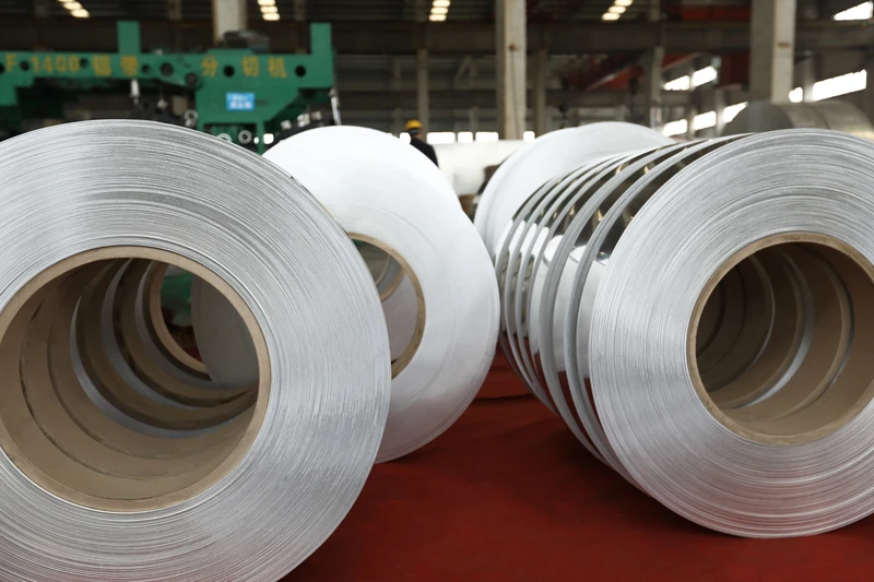
2. Aluminum Foil vs Round Aluminum Wire vs Copper Foil: 4 Parameters Compared
- Aluminum Foil: thickness 0.2-2.0mm, width 50-1,200mm. Lowest power-frequency loss, highest space factor. Drawback: complex end-welding process — dedicated TIG (GTAW) or resistance welding equipment is required.
- Round Aluminum Wire: diameter 1-5mm. Flexible winding, simple end welding. But lower space factor, higher eddy-current loss. Only suitable for sub-800 kVA small transformers.
- Copper Foil: Same dimensions deliver 35-40% lower resistance. But cost is 3-4 times that of aluminum foil — in medium-capacity oil-immersed transformers, it has been replaced by aluminum foil. It is preserved only in high-end scenarios above 1,600 kVA, UHV, and offshore wind power.
- Copper-Clad Aluminum Foil (CCA Foil): Aluminum base + copper layer, performance lies between aluminum foil and copper foil. But the copper layer tends to delaminate after thermal cycling, weakening long-term reliability, so its use in the transformer industry is declining yearly.
3. Key Specifications for Large-Section Aluminum Foil
Four specification parameters must be tightened when procuring aluminum foil for transformer windings:
- Aluminum Foil Thickness Tolerance: Typical thickness 0.5-1.0mm, tolerance ±5%. Foil with thickness variation over ±10% causes resistance deviation of 10%+ that pushes the transformer’s impedance voltage out of design spec.
- Aluminum Foil Width Tolerance: Width 50-1,200mm, tolerance ±0.5mm. Too wide and it pushes against adjacent windings; too narrow and the space factor drops.
- Insulation Coating: Aluminum foil windings must be insulated on both sides — the most common is a polyester film (PET, thickness 0.05-0.10mm) + epoxy resin dual layer; high-end uses NOMEX 410 (aromatic polyamide paper, 0.05-0.25mm).
- Bending Resistance: Aluminum foil windings undergo repeated bending during processing, requiring elongation ≥ 15% — insufficient elongation causes cracking at the radius.
4. Three Typical Application Scenarios for Aluminum Foil Windings
- Oil-Immersed Distribution Transformer (500-2,500 kVA): Aluminum foil windings are most mature in the 11 kV / 33 kV distribution transformer space. Over 75% of European and American oil-immersed distribution transformers use aluminum foil windings, while China’s penetration rate is around 50% and still rising.
- Reactors: Current-limiting reactors, filter reactors, smoothing reactors — aluminum foil’s low skin-effect loss and uniform heat dissipation make DC/DC reactors use aluminum foil almost exclusively.
- Rectifier Transformer / Electrolytic Rectifier: 6-35kV rectifier transformers, aluminum/copper smelter electrolysis — high current + sustained full load unleashes aluminum foil’s space-factor advantage. A 10,000 kA electrolytic rectifier transformer can save RMB 800,000-1.5 million in annual electricity costs.
5. Aluminum Foil vs Round Aluminum Wire Selection Checklist (5 Steps)
- Define Transformer Capacity: Use round aluminum wire below 500 kVA, aluminum foil at 500-2,500 kVA, and compare aluminum foil vs copper foil economics above 2,500 kVA.
- Calculate the Economic Breakpoint: Use copper price ÷ aluminum price = 3.5x as the dividing line. When the copper/aluminum ratio > 3.5, aluminum foil’s economics clearly win; when < 3, copper foil resurges.
- Confirm Insulation System: Polyester film / epoxy dual layer for 130-155°C oil-immersed transformers; NOMEX 410 for 180°C+ high-fire-point oil transformers or dry-type transformers.
- Confirm Supplier Delivery Capability: Aluminum foil width 1,200mm requires large foil rolling mills. Fewer than 10 Chinese factories can stably supply 1,200mm aluminum foil — picking the wrong supplier leaves you without material.
- Cutting + Winding Workshop: Transformer factories must have the equipment capability for aluminum foil cutting, winding tensioning, and end TIG welding — round wire winding machines cannot substitute — the aluminum foil winding tension curve is entirely different.
Practical scenario: a transformer factory received an 800 kVA oil-immersed transformer order from a US customer in 2024 and used aluminum foil windings for the first time. Expecting the 30% cost reduction as a benefit, they overlooked end TIG welding processes, hitting an 18% winding rework rate — directly eating into gross margins. Three months later, the factory invested in a complete TIG welding line to stabilize delivery. The aluminum foil winding trap: real material, but unfinished process.
One last word: large-section aluminum foil winding is not “cheap copper,” it is “an entirely different process route.” Switching a transformer factory to aluminum foil windings requires new mold design, welding machine procurement, and winding operator training — taking 6-12 months. Plants that swap materials only without changing processes have near-certain failures.
One more emerging trend worth mentioning: dry-type transformers are beginning to roll out aluminum foil windings + Vacuum Pressure Impregnation (VPI). The Nomex 410 insulation + epoxy impregnation combination allows dry-type transformers to operate reliably in fire pump rooms, metro stations, and dual-purpose commercial/residential buildings. Aluminum foil penetration in dry-type transformers is expected to break 60% before 2027, again a key inflection market.
As for international OEMs’ preferences: ABB and Siemens in Europe use aluminum foil windings in all 11-33kV oil-immersed transformers. GE and Howard Industries in the US are advancing fully in the 800-2,500 kVA range. Leading Chinese manufacturers such as TBEA, Mingluo Transformer, and Qilu Transformer all have complete aluminum foil product lines — direct references for “late starters.”