
Introduction
Fiberglass covered wire is an important type of insulated conductor in the magnet wire field, widely used in numerous industrial and civilian electrical equipment due to its excellent high-temperature resistance, outstanding mechanical strength, and good electrical insulation properties. With the development of modern electrical equipment toward miniaturization, high efficiency, and high reliability, the performance requirements for winding materials have become increasingly stringent. Fiberglass covered wire,凭借其 unique material advantages and mature manufacturing technology, has become one of the preferred solutions for winding design in high-temperature environments and high mechanical stress conditions.
The manufacturing technology of fiberglass covered wire originated in the mid-20th century. With the continuous advancement of fiberglass material science and insulating varnish technology, its product performance has been significantly improved. Currently, fiberglass covered wire has been widely used in transformers, motors, reactors, household appliances, industrial heating equipment, and other fields, becoming an indispensable and important component of magnet wire product lines.
This article systematically elaborates on the key technical properties of fiberglass covered wire from the aspects of material composition, electrical performance, thermal performance, mechanical properties, chemical performance, environmental resistance, manufacturing processes, application fields, and selection principles, providing comprehensive material selection references for engineering technicians.
1. Material Composition and Structural Characteristics
1.1 Conductor Materials
The conductor materials of fiberglass covered wire are mainly copper or aluminum, with copper conductors occupying the dominant position.
Copper Conductors: Made from oxygen-free copper rods (OFC) as raw materials, processed through multiple drawing passes to the target diameter. The purity of oxygen-free copper is usually above 99.95%, with a conductivity of not less than 100% IACS (International Annealed Copper Standard) and a resistivity of not more than 0.017241 Ω·mm²/m (20℃). High-purity copper conductors ensure that fiberglass covered wire has excellent conductivity and low DC resistance.
Aluminum Conductors: In cost-sensitive application scenarios, high-purity aluminum (above 99.7%) is also used as a conductor material. The conductivity of aluminum conductors is approximately 61% of that of copper, but the density is only 30% of copper, offering significant lightweight advantages.
1.2 Fiberglass Insulation Layer
Fiberglass is the core insulation material of fiberglass covered wire, with the following characteristics:
Chemical Composition: The main component of fiberglass is silicon dioxide (SiO₂, typically 52%~62%), supplemented by aluminum oxide (Al₂O₃), calcium oxide (CaO), magnesium oxide (MgO), boron oxide (B₂O₃), and other oxides. Based on chemical composition differences, fiberglass can be classified into E-glass (electrical glass fiber), S-glass (high-strength glass fiber), and C-glass (chemical-resistant glass fiber). Among these, E-glass is the most widely used in the magnet wire field.
Fiber Diameter: The diameter of fiberglass filaments used for magnet wire covering is typically between 5~13 micrometers. Finer fiber diameters help improve the density and flexibility of the covering layer, but overly fine fibers increase manufacturing difficulty and cost.
Braiding Structure: Fiberglass filaments are braided onto the conductor surface in double or triple layers using specialized braiding equipment. Braiding density and braiding angle are important parameters affecting the performance of the insulation layer. High-density braiding can improve the mechanical strength and voltage resistance of the insulation layer, but will reduce product flexibility.
1.3 Insulation Impregnating Varnish
The fiberglass braided layer itself has certain hygroscopicity and requires impregnation with insulating varnish to improve its electrical performance and moisture resistance. Common types of impregnating varnish include:
Polyester Resin Impregnating Varnish: Has good electrical and mechanical properties at a relatively low cost, suitable for general-purpose fiberglass covered wire. Thermal class is typically Class B (130℃) or Class F (155℃).
Silicone Resin Impregnating Varnish: Has excellent high-temperature resistance and moisture resistance, suitable for high-temperature environments. Thermal class can reach Class H (180℃) or even higher.
Polyurethane Impregnating Varnish: Has good flexibility and wear resistance, suitable for applications requiring frequent bending. Thermal class is typically Class B (130℃).
Modified Epoxy Resin Impregnating Varnish: Has excellent electrical and chemical resistance, suitable for special environments. Thermal class can reach Class F (155℃) or Class H (180℃).
1.4 Structural Characteristics
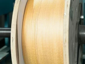
Fiberglass covered wire adopts a composite structure of “conductor + fiberglass braided layer + impregnating varnish”. The conductor is located at the center, the fiberglass braided layer is uniformly coated on the conductor surface, and the impregnating varnish fully penetrates into the fiberglass layer, forming a complete insulation system.
Based on insulation layer thickness, fiberglass covered wire can be classified into thin insulation type, standard type, and thick insulation type. Insulation layer thickness is typically between 0.2~0.8mm, with specific thickness determined by voltage class and operating environment.
2. Electrical Performance
2.1 Insulation Resistance
The insulation resistance of fiberglass covered wire is an important indicator of its insulation performance. Under room temperature (20℃) conditions, the insulation resistance of high-quality fiberglass covered wire is typically not less than 1000 MΩ·km. Under high-temperature conditions (such as 155℃), insulation resistance will decrease but can still be maintained above 50 MΩ·km.
The magnitude of insulation resistance mainly depends on the type and quality of impregnating varnish, the density of the fiberglass, and the perfection of the impregnation process. High-quality impregnating varnish can fully fill the gaps between fiberglass fibers, effectively preventing current leakage and thereby improving insulation resistance.
2.2 Breakdown Voltage
Breakdown voltage is a key indicator of the electrical strength of the fiberglass covered wire insulation layer. The breakdown voltage of standard fiberglass covered wire is typically between 5,000V~15,000V, with specific values depending on insulation layer thickness and impregnating varnish type.
The breakdown voltage of thick insulation type fiberglass covered wire can exceed 15,000V, suitable for high-voltage winding applications. The breakdown voltage of thin insulation type fiberglass covered wire is typically between 3,000V~5,000V, suitable for low-voltage windings.
2.3 Dielectric Constant and Dielectric Loss
The dielectric constant of fiberglass covered wire is typically between 4.0~6.0, and the dielectric loss factor (tanδ) is between 0.01~0.05. A lower dielectric constant and dielectric loss factor help reduce power loss under high-frequency conditions, making fiberglass covered wire suitable for high-frequency power electronic equipment such as high-frequency transformers and high-frequency reactors.
2.4 Arc Resistance
Fiberglass material has excellent arc resistance and can maintain the integrity of the insulation layer under arc action, without melting or carbonizing like some organic insulation materials. This characteristic gives fiberglass covered wire unique advantages in application scenarios where arcs may occur (such as switchgear, circuit breakers, etc.).
3. Thermal Performance
3.1 Thermal Class
The thermal class of fiberglass covered wire mainly depends on the type of impregnating varnish and the thermal resistance of the fiberglass. According to IEC 60085 standard, the thermal class of fiberglass covered wire can be classified as follows:
| Thermal Class | Maximum Operating Temperature | Typical Impregnating Varnish Type |
|---|---|---|
| Class B | 130℃ | Polyester resin |
| Class F | 155℃ | Modified polyester/polyurethane |
| Class H | 180℃ | Silicone resin |
| Class C | 200℃+ | Special silicone/ceramic coating |
Among these, Class H fiberglass covered wire is the most common high-temperature winding wire type, widely used in motors, transformers, and reactors operating in high-temperature environments.
3.2 Thermal Stability
Fiberglass covered wire has good thermal stability under high-temperature conditions. The softening point of fiberglass itself is approximately 800℃~1000℃, and it will not soften or deform within the normal operating temperature range. The thermal stability of the impregnating varnish is the key factor determining the thermal performance of fiberglass covered wire. High-quality silicone impregnating varnish, after long-term operation at 200℃, can still maintain its electrical and mechanical properties at over 80% of the initial values.
3.3 Flame Retardant Properties
Fiberglass itself is a non-combustible material with excellent flame retardant properties. Under high-temperature flame action, fiberglass will not burn, will not release toxic gases, and can effectively prevent flame spread. This characteristic gives fiberglass covered wire important application value in scenarios with strict flame retardant requirements (such as building electrical equipment, rail transit electrical equipment, marine electrical equipment, etc.).
4. Mechanical Properties
4.1 Tensile Strength
The tensile strength of fiberglass is far higher than that of organic fiber materials, with single-filament tensile strength reaching 2,000~3,500 MPa. After being braided into a layer, the tensile strength of fiberglass covered wire mainly depends on the tensile strength of the conductor and the reinforcing effect of the fiberglass braided layer.
The tensile strength of standard fiberglass covered wire is typically between 200~350 MPa, meeting the requirements of most winding processes. Under high mechanical stress conditions (such as large motor rotor windings), tensile strength can be improved by increasing the number of fiberglass braided layers or using high-strength fiberglass.
4.2 Wear Resistance
The wear resistance of fiberglass covered wire is significantly superior to that of ordinary enameled wire. The fiberglass braided layer has high hardness and wear resistance, effectively protecting the conductor from mechanical damage during winding processes such as winding, embedding, and shaping. This characteristic gives fiberglass covered wire obvious advantages in automated winding equipment and high-speed winding processes.
4.3 Flexibility
The flexibility of fiberglass covered wire depends on the diameter of the fiberglass, braiding density, and the flexibility of the impregnating varnish. Fine-diameter fiberglass and low-density braiding help improve product flexibility, but will slightly reduce insulation performance.
In practical applications, the flexibility of fiberglass covered wire can meet the requirements of most winding processes. For applications requiring frequent bending (such as flexible windings, mobile electrical equipment, etc.), flexible type fiberglass covered wire can be selected.
4.4 Cut Resistance
Fiberglass covered wire has excellent cut resistance. During winding processing and operation, the fiberglass braided layer can effectively prevent the conductor from being cut and damaged by sharp edges or burrs, reducing the risk of winding short circuits. This characteristic is particularly important in the manufacturing process of transformers and motors.
5. Chemical Performance
5.1 Solvent Resistance
Fiberglass covered wire has good resistance to most organic solvents. Common organic solvents such as gasoline, kerosene, transformer oil, and lubricating oil have no obvious erosive effect on the insulation layer of fiberglass covered wire.
However, certain strong polar solvents (such as acetone, ethanol, etc.) may cause some swelling effect on the impregnating varnish, and prolonged immersion will lead to a decline in insulation performance. Therefore, in application scenarios involving strong polar solvents, appropriate impregnating varnish types should be selected or additional protective measures should be taken.
5.2 Acid and Alkali Resistance
Fiberglass has good resistance to weak acids and weak alkalis, but in strong acid (such as sulfuric acid, hydrochloric acid) or strong alkali (such as sodium hydroxide) environments, fiberglass will corrode and dissolve. Therefore, fiberglass covered wire is not suitable for use in strong acid or strong alkali environments.
For scenarios requiring use in mildly acidic or alkaline environments, impregnating varnish types with better chemical resistance (such as modified epoxy resin) can be selected, or additional protective coatings can be applied.
5.3 Oil Resistance
Fiberglass covered wire has good resistance to mineral oils such as transformer oil, lubricating oil, and hydraulic oil. In oil-immersed transformers, fiberglass covered wire can operate stably for a long time, and its insulation performance will not significantly decline due to oil erosion.
6. Environmental Resistance
6.1 Moisture Resistance
The fiberglass braided layer itself has certain hygroscopicity, but after impregnating varnish treatment, the moisture resistance of fiberglass covered wire is significantly improved. High-quality impregnating varnish can fully fill the gaps between fiberglass fibers, effectively preventing moisture intrusion.
The moisture absorption rate of impregnation-treated fiberglass covered wire typically does not exceed 2%, and it can maintain good insulation performance in humid environments. For fiberglass covered wire used in high-humidity environments for extended periods, silicone impregnating varnish with better moisture resistance is recommended.
6.2 UV Resistance
Fiberglass itself has good resistance to ultraviolet rays and will not age or degrade due to UV exposure. The UV resistance of impregnating varnish varies by type, with silicone impregnating varnish having better UV resistance than polyester impregnating varnish.
For fiberglass covered wire used outdoors or in UV-exposed environments, impregnating varnish types with better UV resistance should be selected, or additional protective measures should be taken.
6.3 Salt Spray Resistance
Fiberglass covered wire performs well in salt spray environments. Both fiberglass and impregnating varnish have good resistance to salts such as sodium chloride in salt spray, without significant corrosion or degradation.
In scenarios with high salt spray concentrations such as marine environments and coastal areas, fiberglass covered wire is a reliable winding material choice.
6.4 Mold Resistance
Fiberglass is an inorganic material and will not breed mold. The mold resistance of impregnating varnish varies by type, and most impregnating varnishes used for fiberglass covered wire are treated with anti-mold agents to prevent mold growth in humid environments.
For fiberglass covered wire used in high-temperature and high-humidity environments such as tropical and subtropical regions, impregnating varnish types with good mold resistance are recommended.
7. Manufacturing Processes
7.1 Conductor Drawing
The conductor drawing process for fiberglass covered wire is similar to that of ordinary enameled wire. Copper or aluminum rods are drawn to the target diameter through multiple passes, with drawing speed, drawing force, and lubrication conditions controlled during the process to ensure conductor surface quality and dimensional accuracy.
After conductor drawing, annealing treatment is required to eliminate work hardening and restore conductor flexibility and conductivity. The annealing temperature for copper conductors is typically between 400℃~550℃, and for aluminum conductors between 300℃~400℃.
7.2 Fiberglass Braiding
Fiberglass braiding is the core process in fiberglass covered wire manufacturing. Specialized braiding equipment covers the conductor surface with fiberglass filaments at specific braiding density and braiding angle. The number of braided layers is typically two or three, and braiding density can be adjusted according to product specifications and performance requirements.
The following parameters need to be controlled during the braiding process:
Braiding Density: Typically 85%~95%, higher density provides better insulation performance but reduces flexibility.
Braiding Angle: Typically 30°~60°, affecting the tightness and flexibility of the braided layer.
Fiber Tension: Fiber tension should be controlled uniformly to avoid uneven tightness in the braided layer.
7.3 Impregnating Varnish Coating
Impregnating varnish coating is the process of uniformly applying impregnating varnish on the fiberglass braided layer surface and allowing it to fully penetrate into the fiberglass layer. Common coating methods include dip coating, brush coating, and spray coating.
Dip coating involves immersing the braided wire in an impregnating varnish tank, allowing the varnish to fully penetrate into the fiberglass layer, followed by drying and curing. Dip coating has the advantages of uniform coating and sufficient penetration, making it the most commonly used coating method in fiberglass covered wire manufacturing.
The viscosity, solids content, and volatile matter ratio of the impregnating varnish directly affect coating quality. The viscosity of impregnating varnish is typically controlled at 15~25 seconds (Ford Cup 4), with solids content controlled between 40%~60%.
7.4 Drying and Curing
After impregnation, the wire needs to undergo drying and curing treatment to fully cure the impregnating varnish and form a complete insulation layer. Drying and curing are typically carried out in vertical or horizontal ovens, which are divided into preheating zones, curing zones, and cooling zones.
The preheating zone temperature is typically 100℃~150℃, used to evaporate volatile matter in the impregnating varnish. The curing zone temperature is set according to the impregnating varnish type, with polyester varnish curing temperatures typically at 180℃~220℃ and silicone varnish curing temperatures at 200℃~250℃. The cooling zone temperature gradually decreases to room temperature, ensuring uniform curing of the insulation layer.
7.5 Quality Inspection
Quality inspection items for fiberglass covered wire include:
Dimensional Inspection: Conductor diameter, insulation outer diameter, insulation layer thickness.
Electrical Performance: Insulation resistance, breakdown voltage, dielectric loss.
Mechanical Performance: Tensile strength, wear resistance, flexibility.
Thermal Performance: Thermal shrinkage, thermal class, thermal stability.
Appearance Inspection: Insulation layer uniformity, surface defects, color consistency.
8. Application Field Analysis
8.1 Transformer Field
Dry-type Transformers: Fiberglass covered wire is one of the main insulated conductor types for dry-type transformer windings. Class H fiberglass covered wire can operate stably at high temperatures of 180℃ for extended periods, meeting the thermal requirements of dry-type transformers. The flame retardant and moisture resistance properties of fiberglass covered wire enable dry-type transformers to operate safely in space-constrained locations with high environmental safety requirements such as high-rise buildings, basements, and tunnels.
Special Transformers: Rectifier transformers, electric furnace transformers, mining transformers, and other special transformers typically operate in high-temperature, high-humidity, or high mechanical stress conditions. The high-temperature resistance, moisture resistance, and high mechanical strength characteristics of fiberglass covered wire make it the ideal winding material for these special transformers.
Electric Furnace Transformers: Electric furnace transformers operate at extremely high temperatures and typically use Class C fiberglass covered wire to ensure long-term stable operation. The widespread application of fiberglass covered wire in electric furnace transformers provides reliable保障 for the efficient operation of electric furnace equipment.
8.2 Motor Industry
High-Temperature Motors: Large industrial motors in metallurgy, mining, electric power, and other fields typically operate in high-temperature environments. The high-temperature resistance of fiberglass covered wire makes it the preferred winding material for high-temperature motors. Class H and Class C fiberglass covered wire can operate stably at 180℃~220℃ for extended periods, meeting the thermal requirements of high-temperature motors.
Crane Motors: Crane motors need to withstand significant mechanical stress and vibration. The high tensile strength and wear resistance of fiberglass covered wire enable it to adapt to the harsh operating conditions of crane motors, reducing winding failure rates and extending motor service life.
Variable Frequency Motors: Variable frequency motors generate high-frequency harmonics during operation, placing higher demands on the electrical performance of winding insulation materials. The low dielectric constant and low dielectric loss of fiberglass covered wire make it suitable for variable frequency motors.
8.3 Reactors and Other Fields
Industrial Reactors: In various filter reactors, current-limiting reactors, and power factor correction reactors, the high-temperature resistance and arc resistance of fiberglass covered wire make it the preferred solution. Under high-temperature and high-voltage conditions, fiberglass covered wire can maintain stable insulation performance, ensuring the safe operation of reactors.
Household Appliances: The heating element windings of high-temperature household appliances such as ovens, microwave ovens, and rice cookers typically use fiberglass covered wire. The high-temperature resistance and flame retardant properties of fiberglass covered wire enable it to operate safely in high-temperature environments, ensuring the safety of household appliances.
Industrial Heating Equipment: The windings of industrial electric furnaces, heat treatment equipment, drying equipment, and other industrial heating equipment typically use fiberglass covered wire. Fiberglass covered wire can operate stably at temperatures above 200℃ for extended periods, meeting the thermal requirements of industrial heating equipment.
9. Comparison with Other Insulated Conductors
| Comparison Item | Fiberglass Covered Wire | Enameled Wire | Paper Covered Wire | Nomex® Covered Wire |
|---|---|---|---|---|
| Thermal Class | Class B~C (130℃~220℃+) | Class B~C | Class A~E | Class H~C |
| Breakdown Voltage | 5,000V~15,000V+ | 1,000V~5,000V | 3,000V~8,000V | 5,000V~12,000V |
| Mechanical Strength | High | Medium | Low | Medium-High |
| Wear Resistance | Excellent | Good | Poor | Good |
| Flame Retardancy | Excellent | Fair | Poor | Excellent |
| Moisture Resistance | Good | Good | Poor | Excellent |
| Cost | Medium | Low | Low | High |
| Typical Applications | High-temp motors, dry-type transformers | General transformers, motors | Oil-immersed transformers | Special transformers, motors |
10. Selection Recommendations
10.1 Thermal Class Selection
Based on the actual operating temperature of the equipment and the insulation system requirements, select an appropriate thermal class. It is recommended that the design operating temperature be 15~20℃ lower than the rated thermal temperature to allow for a safety margin. For equipment operating in high-temperature environments for extended periods, Class H or Class C fiberglass covered wire should be selected.
10.2 Insulation Layer Thickness Selection
Based on the voltage class and operating environment of the winding, select appropriate insulation layer thickness. High-voltage windings (voltage class >1000V) should use thick insulation type fiberglass covered wire, while low-voltage windings (voltage class <1000V) can use standard type or thin insulation type.
10.3 Impregnating Varnish Type Selection
Select appropriate impregnating varnish type based on the operating environment:
General Purpose: Polyester resin impregnating varnish (Class B or F).
High-Temperature Environment: Silicone resin impregnating varnish (Class H or C).
Requiring Flexibility: Polyurethane impregnating varnish (Class B or F).
Chemical Environment: Modified epoxy resin impregnating varnish (Class F or H).
10.4 Supplier Selection Factors
Certifications: ISO9001 quality management system certification, products comply with IEC 60317, NEMA MW 1000, GB/T 6109, and other standards.
Manufacturing Capabilities: Possesses professional fiberglass covered wire production equipment, can precisely control conductor dimensions, fiberglass braiding density, and impregnating varnish coating quality.
Technical Strength: Can provide complete technical parameters and product inspection reports, helping customers optimize winding design.