


The power density of electronic devices keeps rising every year. A clear fact: within the same package volume, the heat generated keeps increasing. From 5G base stations to new energy vehicle OBCs, to IGBT modules, engineers face the same problem—how to dissipate localized hotspots to a larger surface faster.
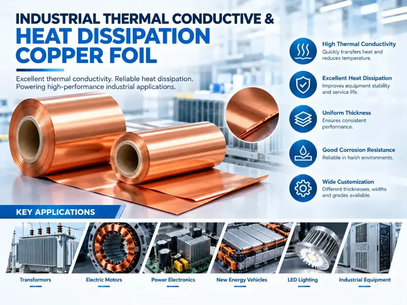
Industrial copper foil plays a critical role in this chain. Its thermal conductivity reaches 390-400 W/m·K, almost 1.5-2× that of aluminum alloy and 1000× that of epoxy resin. Lay a thin layer of copper foil on the PCB inner layer or attach it to the chip bottom, and heat spreads rapidly along the copper foil—then carried away by air cooling, liquid cooling, or phase change materials.
This article walks through industrial thermal conductive and heat dissipation copper foil from an engineering practice perspective—from basic principles, material parameters, standard systems, application scenarios, all the way to selection decisions and key process points.
Basic Principles of Copper Foil Thermal Conductivity
To choose the right copper foil, you must first understand why it conducts and dissipates heat. This section breaks down the basic principles.
Thermal Conductivity Mechanism
Heat transfer in solids occurs in three ways—conduction, convection, and radiation. Copper foil primarily participates in conduction. Conduction is the diffusion of heat from the high-temperature end to the low-temperature end along the material itself; essentially, it is the synergy of lattice vibrations (phonons) and free electron movement.
Copper’s thermal conductivity advantage comes mainly from free electrons. Copper has the second highest electrical conductivity among metals (after silver), and correspondingly, high free electron density. These electrons not only conduct electricity but also transport energy at high speed between crystal lattices. So copper naturally has high thermal conductivity—pure copper at 25°C is 401 W/m·K.
The form of foil does not change this mechanism. Whether electrolytic copper foil (ED) or rolled copper foil (WR), copper’s inherent thermal conductivity remains. The difference lies in foil thickness, surface condition, and purity, which affect actual thermal resistance. This will be expanded later.
Relationship Between Thermal Resistance and Thermal Conductivity
Many customers’ first question is: Does thicker copper foil mean better heat dissipation?
Answer: not exactly. Thermal resistance R = L / (k × A), where L is the heat conduction path length (i.e., copper foil thickness), k is thermal conductivity, A is cross-sectional area. The formula shows that with fixed thermal conductivity k, the smaller the thickness L, the lower the thermal resistance. So thinner copper foil actually has lower thermal resistance for the same area.
But if it gets too thin, problems arise—insufficient mechanical strength, easy tearing. So in practice, choose the thinnest foil that still ensures mechanical strength. 35 μm, 70 μm, and 105 μm are the three most common thickness grades.
Heat Dissipation Mechanism
Heat conduction is the first step; heat dissipation is the end. Copper foil itself does not dissipate heat—it is merely a “transporter.” Real heat dissipation relies on convection and radiation.
In industrial settings, the typical heat dissipation path for copper foil is: chip → thermal interface material (TIM) → copper foil → air-cooled/liquid-cooled heatsink → ambient air. Copper foil “flattens” the hotspot over a larger area, making convection easier.
For example—a 10 mm × 10 mm chip generates 50 W of heat. Without copper foil, the heat flux density is 500 W/cm², which a conventional heatsink cannot handle. After laying copper foil covering the entire PCB, the heat flux density drops to 1-5 W/cm²—at which point even a regular aluminum extrusion heatsink can manage.
Key Parameters and Materials of Industrial Copper Foil
Copper foil selection is not simply “thicker is better” or “purer is better.” This section clarifies the key parameters and material systems.
Thickness Specifications
Industrial copper foil is categorized into three types by thickness: ultra-thin (≤18 μm), standard (35-105 μm), thick foil (140-700 μm). Different application scenarios require different thicknesses.
PCB inner layer heat dissipation uses 35-70 μm; power battery module heat dissipation uses 70-105 μm; IGBT substrates use 105-210 μm; new energy vehicle OBC heat sinks even use thick foil of 400 μm and above.
ASTM B370 is the industrial copper foil thickness standard—covering 0.00635 mm (1/4 oz) to 3.175 mm. In width, a single roll can reach 1370 mm.
Material Grades
The two most common industrial copper foil grades are C1100 and C1220.
C1100 is pure copper with copper content ≥99.95%, highest thermal conductivity (close to pure copper theoretical 401 W/m·K). But it is sensitive to annealing temperature and easily deformed in soft state.
C1220 is phosphorus-containing deoxidized copper, phosphorus content approximately 0.015-0.040%. Phosphorus improves heat resistance and softening resistance of copper foil, at the cost of slightly lower thermal conductivity (390-395 W/m·K). Suitable for high-temperature environments or applications requiring subsequent soldering.
For special applications with higher purity requirements (such as vacuum equipment, superconducting magnets), C10100 oxygen-free copper (OFC) is used, copper content ≥99.99%. But cost goes up too.
Surface Condition
The surface condition of copper foil directly affects its contact thermal resistance with the thermal interface material (TIM). The lower the roughness Ra, the better the interface contact, and the lower the thermal resistance.
Electrolytic copper foil (ED) has relatively rough surface (Ra 1-3 μm), but strong adhesion to resin—so suitable for PCB inner layer copper foil.
Rolled copper foil (WR) has smooth surface (Ra ≤0.5 μm), but weak adhesion to resin—so suitable for TIM carrier or direct bonding to metal surfaces.
Graphene-coated copper foil is a new direction in 2024. A study published in MDPI journal in June shows—graphene coatings can further improve the effective thermal conductivity of copper foil by 20-30% while reducing interfacial thermal resistance. Suitable for high-power, small-volume, high-power-density electronic devices.
Mechanical Properties
Copper foil in engineering applications must not only conduct heat but also withstand mechanical stress. Tensile strength, elongation, and hardness are the three parameters that determine whether the copper foil can withstand assembly, vibration, and thermal cycling.
C1100 in annealed state has tensile strength of 220-280 MPa, elongation 35-45%. C1220 in semi-hard state has tensile strength 280-350 MPa, elongation 10-20%. The specific state chosen depends on the processing method—stamping, bending, stretching have different requirements for copper foil plasticity.
Material Thermal Conductivity and Heat Dissipation Comparison
Comparing the most common heat dissipation materials in industry side-by-side gives a clear view of copper foil’s position.
| Material | Thermal Conductivity W/m·K | Density g/cm³ | Tensile Strength MPa | Main Advantages | Main Limitations |
|---|---|---|---|---|---|
| Pure Copper C1100 | 390-401 | 8.96 | 220-280 | Highest thermal conductivity, mature process | Heavy weight, high cost |
| Deoxidized Copper C1220 | 385-395 | 8.94 | 280-350 | Resistant to softening, good weldability | Slightly reduced thermal conductivity |
| Aluminum Foil 1 Series | 200-230 | 2.70 | 80-150 | Lightweight, cost-effective | Moderate thermal conductivity |
| Graphene-Coated Copper Foil | 480-520 | 8.95 | 240-300 | Effective thermal conductivity increased 20-30% | High cost, new process |
| Copper-Aluminum Composite Foil | 250-380 | 4.5-7.0 | 180-260 | Weight/thermal conductivity tradeoff | Complex interface bonding process |
The key significance of this table is that copper’s thermal conductivity is 1.7-2× that of aluminum. So whenever the power density exceeds 3 W/cm², engineers will prioritize copper foil over aluminum foil. Graphene coating is a new option after 2024, suitable for high-end applications where cost is not a concern.
Standard System
The industrial copper foil standard system is more fragmented than enameled wire. This section clearly lists the main standards—especially important for those handling export orders.
International Standards
ASTM B370 is the most commonly used industrial copper foil specification standard in the North American system, covering thickness, width, mechanical properties, and electrical conductivity.
IPC-4562 is the standard for copper foil used in printed circuit boards (PCBs). Grades 1-3 correspond to different surface treatments and precision requirements. The classification of electrolytic copper foil (ED/RA) and rolled copper foil (WR) is also in this standard.
IEC 60243 is the electrical strength testing method standard—used to test insulation coordination and breakdown voltage of copper foil. Rarely used in thermal conductivity scenarios, but required when electrical insulation is involved.
ASTM D5470 is the standard test method for thermal interface materials (TIM). When copper foil is part of a TIM (carrier or directly involved in thermal conduction), this method is required to calibrate its thermal resistance.
Chinese Standards
GB/T 5230 is the Chinese industrial copper foil standard adopting the IEC standard. Export companies control production according to this standard domestically, then use ASTM or IPC standards for overseas production.
SJ/T 11483 is the Chinese electronics industry standard—specifically for PCB copper foil. Equivalent to IPC-4562.
Standard Collaboration
In actual engineering, standards are often used in combination. For example, copper foil for power battery module heat dissipation is first controlled per ASTM B370 for thickness and purity, then per IPC-4562 for surface condition, and finally per ASTM D5470 for thermal resistance testing.
Those unfamiliar with standards easily fall into a trap—mixing test methods from different standards. ASTM and IEC have different test temperature and humidity conditions, so data cannot be directly compared. Must follow the same standard system.
Comparison of Major Industrial Copper Foil Standards
The core standards are compiled by application field to facilitate standard alignment for export orders.
| Standard | Applicable Object | Thickness Range | Core Parameters | Major Markets |
|---|---|---|---|---|
| ASTM B370 | Industrial Pure Copper Foil | 0.00635-3.175 mm | Thickness, Width, Mechanical Properties, Electrical Conductivity | North America |
| IPC-4562 | Copper Foil for PCB | 5-210 μm | Surface Condition, Grade | Global PCB |
| IEC 60243 | Electrical Strength Testing | — | Breakdown Voltage, Insulation Coordination | Global Electrical |
| ASTM D5470 | Thermal Interface Materials | — | Thermal Resistance, Thermal Conductivity | Global Thermal |
| GB/T 5230 | Industrial Pure Copper Foil | 0.00635-3.175 mm | Equivalent to IEC | China |
| SJ/T 11483 | Copper Foil for PCB | 5-210 μm | Equivalent to IPC-4562 | China |
Two points need special attention in this table—first, ASTM B370 and GB/T 5230 are different language versions of the same standard, directly interchangeable; second, ASTM D5470 is the TIM test method, all projects using copper foil as TIM carrier will use this standard.
Application Scenarios
Copper foil industrial applications have penetrated many fields. This section discusses them by scenario—the needs of each scenario are actually quite different.
Electronics and Power Field
PCB inner layer heat dissipation is the largest application scenario for copper foil. 5G base stations, servers, data center switches—the PCBs of these devices all have built-in copper foil heat dissipation layers. Copper foil is laid in the PCB inner layer (between FR-4 substrate), laterally diffusing heat generated by chips.
IGBT module substrate is another important scenario. Industrial frequency converters, photovoltaic inverters, electric vehicle drives—these high-power devices all require substrate heat dissipation. Direct bonded copper (DBC) ceramic substrates and direct bonded aluminum (DBA) substrates both use copper foil. IGBT module substrate copper foil thickness is typically between 200-600 μm.
New energy vehicle OBC (on-board charger) and DC-DC converters are emerging explosive applications. OBC power density keeps increasing, from early 30 W/in³ to current 60-90 W/in³. Copper foil here is not only a thermal conductive material but also part of the electromagnetic shielding.
New Energy Field
Photovoltaic inverters are a stable growth market for copper foil. PV inverter power ranges from 3 kW (residential) to 6 MW (centralized power plants), and higher power means more copper foil usage. A single 100 kW PV inverter uses approximately 5-10 square meters of copper foil.
Energy storage systems (ESS) are another incremental market. Energy storage battery module heat dissipation requirements are similar to power batteries, but on a larger scale. A 1 MWh energy storage unit typically requires 20-50 square meters of copper foil to build the heat dissipation network.
Communications Field
5G base station AAU/RRU units are high-end copper foil applications. 5G base station power density is 3-5× that of 4G, sharply increasing heat dissipation pressure. The PCB inside the AAU must use thick copper foil (≥4 oz) to dissipate the heat from the power amplifier chip.
Optical modules are another precision application. Optical modules are small in size (QSFP-DD package only 18 mm × 47 mm × 8.5 mm), but heat dissipation requirements are high. Optical module internal PCB uses 2-3 oz copper foil, thermal resistance must be controlled below 0.5°C/W.
GPU accelerator cards in servers and data centers are another emerging demand for copper foil. NVIDIA H100 GPU single-chip power consumption is 700 W, thermal design power (TDP) far exceeds ordinary CPUs. GPU card PCB has 6-10 layers of copper foil built-in, each layer 2-4 oz.
Industrial Equipment and Automotive
Industrial motor drivers use copper foil as insulation heat dissipation layer. The PCB inside the driver has both power devices (IGBTs, MOSFETs) and control circuits. Copper foil provides heat dissipation under power devices and electromagnetic shielding under control circuits.
Industrial heating equipment induction coils use thick copper foil. Induction heating operates at frequencies from 10 kHz to 1 MHz, copper foil skin effect limits current distribution. So high-frequency induction heating uses thin copper foil (35-70 μm), low-frequency industrial furnaces use thick copper foil (≥210 μm).
Automotive electronics ECUs, sensors are stable industrial applications. Automotive-grade copper foil requires -40°C to +125°C wide temperature operation, and must pass AEC-Q100/Q200 certification.
Heat Dissipation Process and Manufacturing
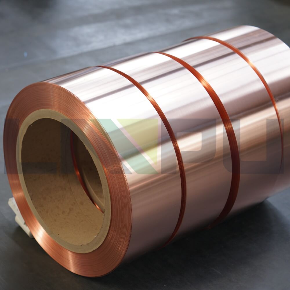
Copper foil has multiple use modes in industrial heat dissipation scenarios—directly laid on PCB inner layer, attached to chip surface, or embedded in metal substrate.
PCB inner layer copper foil is fixed through lamination process. Copper foil and prepreg are thermo-pressed together, copper foil embedded in PCB inner layer. This method has stable thermal conduction path, but can only be used on PCB itself.
Chip surface copper foil is bonded through thermal interface material (TIM). TIM is generally thermal grease, thermal gel, or thermal pad. Copper foil is attached above TIM, conducting heat from chip surface to heatsink. This method is flexible, but TIM’s own thermal conductivity limits the total thermal resistance.
Metal substrate (IMS) copper foil is bonded to aluminum or copper substrate through insulating dielectric layer. Insulating dielectric is generally ceramic-filled epoxy resin. This method has strong heat dissipation capability, suitable for high-power applications like LED and motor driving.
Selection Decision Process
Selection is not by intuition—this section breaks down the decision process into 5 steps. Each step has specific engineering parameters for reference.
Step 1 Evaluate Application Scenario
First step is to clarify the application scenario. PCB inner layer heat dissipation? IGBT substrate? Or TIM carrier? Different scenarios have different priority of key parameters for copper foil.
PCB inner layer heat dissipation prioritizes surface condition (Ra and adhesion); IGBT substrate prioritizes thickness and thermal conductivity; TIM carrier prioritizes surface smoothness and flatness.
When the application scenario is uncertain, choose copper foil for PCB inner layer heat dissipation first—this scenario covers more than 70% of industrial applications.
Step 2 Evaluate Power Density
Second step is to evaluate power density. Power density = Total power consumption / Heat dissipation area. The higher the power density, the stronger the heat dissipation capacity of copper foil required.
Reference Tiers:
– Low power density (<0.5 W/cm²): 35 μm copper foil is sufficient
– Medium power density (0.5-3 W/cm²): 70-105 μm copper foil
– High power density (3-10 W/cm²): 140-210 μm copper foil
– Ultra-high power density (>10 W/cm²): 300 μm and above thick foil, or direct bonded substrate
5G base station AAU, new energy vehicle OBC, IGBT modules are all in high power density range, requiring 105 μm and above copper foil.
Step 3 Evaluate Operating Temperature
Third step is to evaluate operating temperature. Copper foil itself has a wide operating temperature range (-196°C to +250°C), but thermal interface material (TIM) and substrate material operating temperatures are the limiting factors.
Operating temperature <150°C: C1100 is sufficient, C1100 has stable thermal conductivity in this temperature range.
Operating temperature 150-200°C: C1220 is more suitable, phosphorus improves resistance to softening.
Operating temperature >200°C: Consider graphene-coated copper foil or direct bonded aluminum substrate (DBA).
NEMA MW 1000 standard specifies MW 53-C (polyester fiberglass-coated copper foil) as thermal class 180°C—a common benchmark for industrial copper foil.
Step 4 Evaluate Cost
Fourth step is to evaluate cost. Copper foil typically accounts for 15-30% of cost in industrial heat dissipation systems. Cost-sensitive applications need to balance performance and cost.
Per Standards:
– 35 μm C1100 copper foil (PCB inner layer): approximately 80-120 RMB/square meter
– 70 μm C1100 copper foil (general industrial): approximately 150-220 RMB/square meter
– 105 μm C1100 copper foil (power battery): approximately 220-320 RMB/square meter
– 140-210 μm C1220 thick foil (IGBT substrate): approximately 350-550 RMB/square meter
– 35-70 μm graphene-coated copper foil: approximately 600-1000 RMB/square meter
Bulk purchases (≥1000 square meters) typically receive a 10-20% discount. Long-term cooperative clients can obtain more stable prices.
Step 5 Verification and Material Preparation
Fifth step is verification and material preparation. Sample verification must include at least three tests: thermal conductivity, thermal resistance cycling, and reliability.
Thermal conductivity test uses ASTM D5470 standard method. Thermal resistance cycling test (-40°C to +125°C, 1000 cycles) verifies bonding strength between copper foil and TIM/substrate. Reliability tests include high temperature high humidity (85°C/85% RH, 1000 hours) and temperature shock (-55°C to +150°C, 500 cycles).
After sample verification passes, prepare in engineering batches (500-1000 square meters). Then mass production batches (5000+ square meters). Any quality issues discovered at any stage must be promptly reported to the copper foil supplier.
Selection Quick Reference Table
The most critical parameters in the 5-step decision process are summarized in one table for quick reference by engineers.
| Power Density | Recommended Thickness | Recommended Grade | Typical Applications | Price RMB/m² | Remarks |
|---|---|---|---|---|---|
| <0.5 W/cm² | 35 μm | C1100 | PCB Inner Layer, LED Light Board | 80-120 | Cost Sensitive |
| 0.5-3 W/cm² | 70-105 μm | C1100 | Energy Storage Battery, Consumer Electronics | 150-320 | General Industrial |
| 3-10 W/cm² | 105-210 μm | C1220 | IGBT Substrate, New Energy OBC | 280-550 | High Power Devices |
| >10 W/cm² | 300-700 μm | C1220 + DBC/DBA | High-Speed Rail Traction, PV Inverter | 500-1200 | Thick Foil or Substrate |
The design logic of this table is that the power density tier determines copper foil thickness and grade, which in turn determines the cost range. Budget-tight projects can go down one tier (sacrificing some heat dissipation margin), budget-comfortable high-end projects can choose one tier up (improving heat dissipation capability).
Summary
Industrial thermal conductive and heat dissipation copper foil is an indispensable basic material for modern electronic and electrical equipment. Its high thermal conductivity (390-400 W/m·K), good processability, and mature supply chain make it almost irreplaceable in high-power heat dissipation scenarios. The core of selection is to match application scenario’s power density, operating temperature, and cost budget—C1100 and C1220 are the two most common grades, ASTM B370 and IPC-4562 are the two most frequently encountered standards.
In terms of applications, industrial thermal conductive and heat dissipation copper foil has expanded from early PCB inner layer heat dissipation to multiple high-growth fields such as IGBT substrates, new energy vehicle OBCs, 5G base stations, energy storage systems, and photovoltaic inverters. Each field’s copper foil demand structure is different—PCB inner layer prioritizes surface condition and adhesion, IGBT substrate prioritizes thickness and flatness, new energy vehicle OBC prioritizes high-temperature stability and electromagnetic compatibility. It is recommended that engineers evaluate each item using the 5-step method in this article, then make final decision based on specific application scenario.
In terms of quality control, the key control points for industrial copper foil are thickness tolerance, surface Ra value, thermal conductivity, thermal resistance cycling, and batch consistency. ASTM B370 specifies thickness tolerance within ±5%, ASTM D5470 is the standard thermal resistance test method. It is recommended to require suppliers to provide test reports for each batch during procurement, and conduct regular third-party sampling inspections to ensure stable and reliable copper foil quality.