


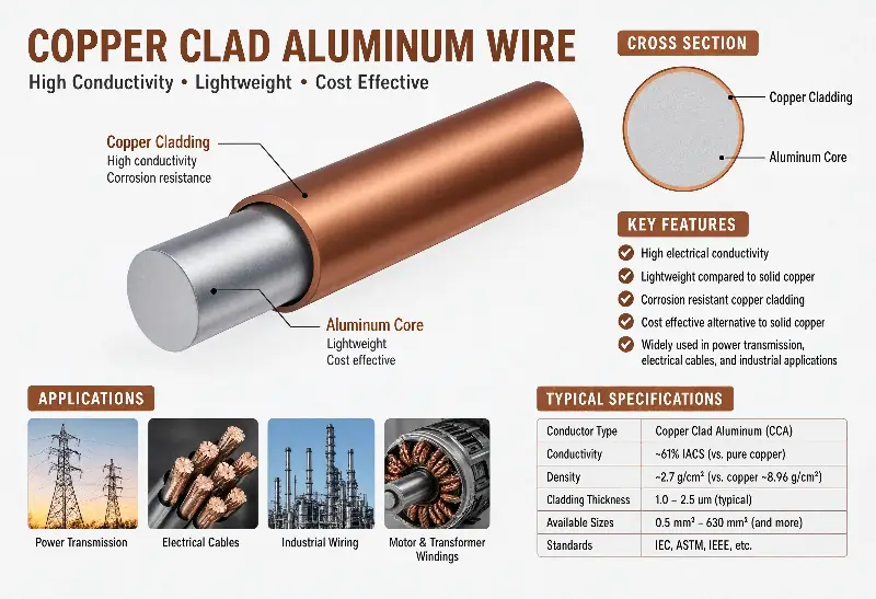
Copper Clad Aluminum Wire (CCA Wire, CCAW), a bimetallic composite conductor, leverages the low density of its aluminum core (2.70 g/cm³, i.e., 30% that of copper) and the high electrical conductivity, solderability, and corrosion resistance of its outer copper layer. It has gained widespread engineering application in high-frequency signal transmission (CATV coaxial cables, cable television, RF antennas), audio voice coils (subwoofers, automotive audio systems), enameled wire coils (ECCA enameled wire, copper-clad aluminum enameled wire), power cables, communication cables, specialty transformers, household appliance compressors, UPS power supplies, inductor windings, automotive electronics, and battery interconnects.
However, the “composite structure” characteristic of CCA wire—where the copper layer and aluminum core are permanently bonded via metallurgical bonding (continuous welding) or electroplating—renders its quality evaluation system significantly more complex than that for single-metal conductors (e.g., pure copper or pure aluminum). Any quality deficiency—including copper layer thickness deviation, insufficient copper–aluminum bond strength, enamel film discontinuity, reduced conductivity, noncompliant peel strength, out-of-specification density (either excessive or insufficient), poor solderability, or substandard elongation—may manifest in end-use applications as abnormal signal attenuation, excessive temperature rise, cracking at connection points, enamel breakdown, or winding fracture. Therefore, establishing a systematic, standardized, and quantifiable CCA wire quality testing system is a core engineering requirement shared by CCA manufacturers, wire and cable producers, and end users (OEMs).
This document comprehensively addresses the general principles and standards framework for CCA wire quality testing; conductor visual appearance and dimensional testing; DC resistance and conductivity testing; copper layer thickness and volumetric copper content testing; density and compositional analysis; copper–aluminum bond strength testing (peel/shear); mechanical property testing (elongation, tensile strength, flexibility); enamel film continuity and dielectric performance testing; insulation thermal class and thermal shock testing; solderability and connection reliability testing; corrosion and aging testing; batch sampling and acceptance criteria; common quality defects and diagnostic methods; laboratory test equipment configuration; cross-referencing of ASTM/IEC/GB standards; third-party testing and quality assurance; and engineering practice recommendations for CCA wire quality testing—providing a complete technical testing and quality control guide for cable engineers, QA/QC personnel, CCA wire purchasers, OEMs, and third-party testing laboratories.
General Principles and Standards Framework for CCA Wire Quality Testing
CCA wire quality testing is not a pass/fail assessment based on a single parameter, but rather a multidimensional evaluation system covering the conductor, insulation, interfacial bonding, and application suitability.
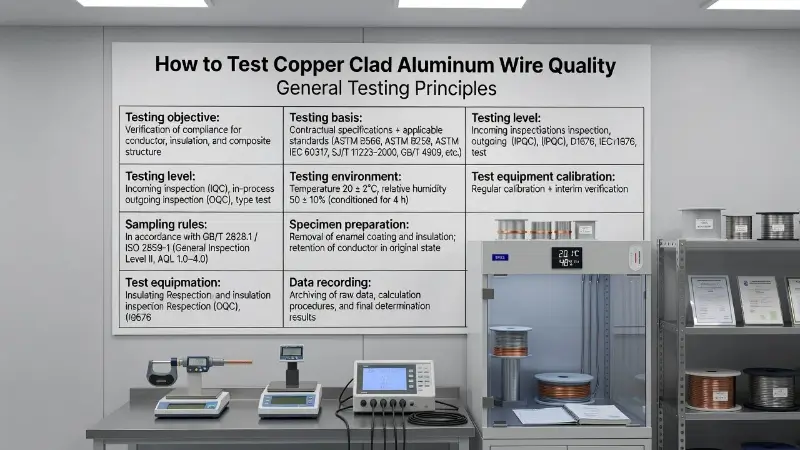
General Testing Principles
CCA wire quality testing shall adhere to the following fundamental principles:
- Testing objective: Verification of compliance for conductor, insulation, and composite structure
- Testing basis: Contractual specifications + applicable standards (ASTM B566, ASTM B258, ASTM D1676, IEC 60317, SJ/T 11223–2000, GB/T 4909, etc.)
- Testing level: Incoming inspection (IQC), in-process inspection (IPQC), outgoing inspection (OQC), type test
- Testing environment: Temperature 20 ± 2°C, relative humidity 50 ± 10% (conditioned for 4 h)
- Sampling rules: In accordance with GB/T 2828.1 / ISO 2859-1 (General Inspection Level II, AQL 1.0–4.0)
- Specimen preparation: Removal of enamel coating and insulation; retention of conductor in original state
- Test equipment calibration: Regular calibration + interim verification
- Data recording: Archiving of raw data, calculation procedures, and final determination results
Applicable Standards Framework
| Standard | Scope | Applicable Product |
|---|---|---|
| ASTM B566 | Standard Specification for Copper-Clad Aluminum Wire | Bare CCA wire |
| ASTM B258 | Standard Specification for Standard Sizes of Round Solid Wires | Wire diameter, cross-sectional area |
| ASTM D1676 | Standard Test Methods for Insulating Film of Enamel-Coated (Magnet) Wire | ECCA enameled wire |
| ASTM B559 | Standard Specification for Nickel-Plated Copper-Clad Steel Wire | Reference standard (interfacial bonding) |
| IEC 60317 | Series of standards for enamelled winding wires | ECCA enameled wire |
| SJ/T 11223–2000 | Electronic Industry Standard of the People’s Republic of China | CCA wire |
| GB/T 4909 | Test Methods for Enamelled Winding Wires | ECCA enameled wire |
| NEMA MW 1000 | Comprehensive U.S. standard for magnet wire | Enamel film classification |
Test Categories and Applicable Stages
| Test Category | Applicable Stage | Key Parameters |
|---|---|---|
| Incoming Inspection | Procurement/receiving | Dimensions, resistance, copper content, enamel film |
| In-Process Inspection | During production | Copper layer thickness, bond strength, enamel continuity |
| Outgoing Inspection | Final product release | Full type test + sampling |
| Type Test | New product launch / process change | Full test suite |
| Third-Party Testing | Dispute resolution / certification | Full standard-compliant testing |
Conductor Visual Appearance and Dimensional Testing
Conductor visual appearance and dimensions constitute the most fundamental inspection items for CCA wire, directly influencing mechanical assembly, electrical performance, and downstream process compatibility.
Visual Inspection
Visual inspection serves as the first line of defense in quality testing, primarily identifying surface defects, geometric anomalies, and contamination.
Inspection Items:
- Surface finish: Bright, semi-bright, or dark grade
- Surface defects: Scratches, indentations, pitting, flaking, burrs, oxidation spots, copper nodules
- Color consistency: Copper-red, rose-gold, or deep red (darkening upon oxidation)
- Surface contamination: Oil residue, dust, fingerprints, residual enamel, lubricant residue
- Geometric defects: Excessive ovality, bow, twist, wave
Inspection Method:
- Illumination: Natural light or D65 standard illuminant
- Viewing distance: 300–500 mm
- Magnification: 10× magnifier when required
- Defect classification: Critical (reject), Major (conditional acceptance), Minor (accept)
- Sampling: In accordance with GB/T 2828.1 General Inspection Level II
Diameter and Ovality Testing
Diameter accuracy directly impacts resistance calculation, winding process, enamel uniformity, and connector mating.
Testing Method:
- Instruments: Micrometer (0.001 mm resolution), laser diameter gauge (online/offline)
- Measurement points: At both ends and midpoint of each specimen (minimum 3 points)
- Measurement orientation: Two mutually perpendicular directions per cross-section
- Ovality = Maximum diameter − Minimum diameter
- Permissible tolerance: Typically ±0.002 mm (fine gauges), ±0.01 mm (coarse gauges)
- ASTM B258 specifies AWG-to-metric equivalences (e.g., AWG 30 = 0.255 mm, AWG 24 = 0.511 mm, AWG 20 = 0.813 mm)
Typical Gauges and Permissible Tolerances (per ASTM B258):
| AWG | Diameter (mm) | Permissible Tolerance (mm) | Ovality (mm) |
|---|---|---|---|
| AWG 22 | 0.644 | ±0.005 | ≤0.005 |
| AWG 24 | 0.511 | ±0.005 | ≤0.005 |
| AWG 26 | 0.404 | ±0.004 | ≤0.004 |
| AWG 28 | 0.320 | ±0.003 | ≤0.003 |
| AWG 30 | 0.255 | ±0.003 | ≤0.003 |
| AWG 32 | 0.202 | ±0.002 | ≤0.002 |
| AWG 34 | 0.160 | ±0.002 | ≤0.002 |
| AWG 36 | 0.127 | ±0.002 | ≤0.002 |
Cross-Sectional Area and Mass Testing
Cross-sectional area and mass are used to verify resistance calculations, density conversion, and copper–aluminum ratio.
Testing Method:
- Cross-sectional area: Calculated from diameter: A = π × (d/2)²
- Mass per unit length: Precision balance (0.0001 g resolution) + length measurement (≥1 m)
- Mass deviation: Percentage deviation from nominal mass
Conductor DC Resistance and Conductivity Testing
DC resistance is the core parameter for evaluating the electrical conduction capability of CCA wire, directly reflecting copper layer thickness, aluminum core purity, and copper–aluminum interfacial bond quality.
DC Resistance Testing Method
Testing Method:
- Applicable standards: GB/T 3048.2, ASTM B193, IEC 60228
- Principle: Four-terminal (Kelvin four-wire) method to eliminate contact resistance
- Test temperature: 20°C (standard reference temperature)
- Specimen length: ≥1 m (accuracy ±0.1%)
- Test current: 1–10 A (selected according to wire gauge to avoid self-heating)
- Temperature correction: R₂₀ = Rₜ × [1 + α × (20 − t)], where α is the temperature coefficient of resistance
Key Parameters:
- Resistivity unit: Ω·mm²/m
- Conductivity unit: % IACS (International Annealed Copper Standard)
- Pure copper, 100% IACS = 0.01724 Ω·mm²/m @ 20°C
- Pure aluminum, 61% IACS = 0.0282 Ω·mm²/m @ 20°C
- Typical CCA wire resistivity: 0.0240–0.0270 Ω·mm²/m
- 10A grade (10% Cu): 0.0270 Ω·mm²/m
- 15A grade (15% Cu): 0.0255 Ω·mm²/m
- 20A grade (20% Cu): 0.0240 Ω·mm²/m
- 25A grade (25% Cu): 0.0230 Ω·mm²/m
- 30A grade (30% Cu): 0.0220 Ω·mm²/m
Conductivity (% IACS) Calculation
Formula:
- %IACS = (0.01724 / ρ₂₀) × 100%
- Where ρ₂₀ is the resistivity at 20°C (Ω·mm²/m)
- Typical CCA wire %IACS range: 63–72%
- 10A grade: 63% IACS
- 15A grade: 67% IACS
- 20A grade: 72% IACS
- 25A grade: 75% IACS
- 30A grade: 78% IACS
Test Equipment
- DC resistance bridge (QJ57, QJ84)
- Micro-ohmmeter (typical range: 1 μΩ – 200 Ω)
- Digital multimeter (≥4½ digits, Kelvin clips)
- Temperature-controlled water bath (20 ± 0.1°C, for precise measurement)
- Automatic resistance tester (in-line production use)
Common Nonconformance Causes
- Insufficient copper layer thickness
- Aluminum core purity below specification (excessive impurities)
- Oxide layer or voids at the copper–aluminum interface
- Inadequate annealing (elevated resistance)
- Reduced wire diameter
- Non-uniform copper layer
Copper Layer Thickness and Volume Ratio Testing
Copper layer thickness and copper volume ratio are the core distinguishing parameters of CCA wire versus pure copper or pure aluminum conductors, directly determining conductivity, solderability, connection reliability, and cost.
Copper Volume Ratio
Definition: Percentage of copper layer volume relative to the total conductor cross-sectional area (Vol%).
ASTM B566 Standard Grades:
| Grade | Copper Volume Ratio | Typical Application |
|---|---|---|
| 10A / 10H | 10% | High-frequency signals, RF cables |
| 15A / 15H | 15% | CATV coaxial cables, audio voice coils |
| 20A / 20H | 20% | General power cables, interconnect wires |
| 25A / 25H | 25% | Magnet wire (ECCA), high-conductivity applications |
| 30A / 30H | 30% | Transformers, battery interconnects |
Test Methods:
- Metallographic cross-sectioning: most accurate (destructive)
- Microscopic image analysis: software-based copper layer area measurement
- Gravimetric method: weight difference before and after copper layer stripping
- Eddy current thickness gauge: non-destructive, in-line testing
- X-ray fluorescence (XRF): surface compositional analysis (non-destructive)
- Density back-calculation method: copper content derived from overall density
Metallographic Cross-Section Testing (Reference Method)
Procedure:
- Sampling: cut a 10–20 mm length specimen
- Mounting: hot or cold mounting (epoxy resin + hardener)
- Grinding: SiC abrasive papers, sequentially 180#, 400#, 800#, 1200#, 2000#
- Polishing: diamond polishing paste (1 μm, then 0.25 μm)
- Etching: nitric acid + hydrofluoric acid + water (NH₄OH·H₂O + HNO₃ mixture, for copper–aluminum differentiation)
- Microscopic observation: metallographic microscope at 100×–500× magnification
- Measurement: radial copper layer thickness, copper layer area, total cross-sectional area
- Calculation: Copper volume ratio = (copper layer area / total cross-sectional area) × 100%
Eddy Current Thickness Measurement (In-line / Rapid)
Principle:
- An eddy current probe generates an alternating magnetic field in its coil
- The magnetic field induces eddy currents in the copper layer
- These eddy currents produce a counter-field affecting probe impedance
- Impedance variation correlates with copper layer thickness
- Requires calibration using certified reference standards
Advantages:
- Non-destructive
- Rapid (sub-second per measurement)
- Enables 100% in-line inspection
- Suitable for high-volume production
Limitations:
- Measures only surface copper layer
- Sensitive to copper layer uniformity
- Requires frequent recalibration
Copper Layer Thickness (μm) Conversion Table
| Wire Diameter (mm) | 10% Cu Thickness (μm) | 15% Cu Thickness (μm) | 20% Cu Thickness (μm) | 30% Cu Thickness (μm) |
|---|---|---|---|---|
| 0.10 | 2.6 | 4.0 | 5.5 | 8.6 |
| 0.20 | 5.2 | 8.0 | 11.0 | 17.1 |
| 0.30 | 7.7 | 12.0 | 16.5 | 25.7 |
| 0.50 | 12.9 | 20.1 | 27.5 | 42.8 |
| 0.80 | 20.6 | 32.1 | 44.0 | 68.5 |
| 1.00 | 25.8 | 40.1 | 55.0 | 85.6 |
Density and Composition Testing
Density provides a rapid means to verify copper–aluminum ratio and authenticate material composition.
Density Testing Methods
Archimedes’ Principle Method:
- Equipment: precision balance (0.0001 g), density attachment, deionized water (or liquid of known density)
- Procedure: measure mass in air (m₁), then mass immersed in liquid (m₂)
- Formula: ρ = m₁ × ρ_liquid / (m₁ − m₂)
- Specimen length: ≥100 mm (to minimize error)
- Specimen surface: clean, bubble-free
- Liquid temperature: 20 ± 0.5°C
Theoretical Density Reference (Based on Cu–Al Volume Ratio):
| Cu Volume Ratio (%) | Density (g/cm³) | Cu Weight Ratio (%) | Al Weight Ratio (%) |
|---|---|---|---|
| 10% | 3.63 | 24.2% | 75.8% |
| 15% | 3.96 | 33.6% | 66.4% |
| 20% | 4.27 | 41.5% | 58.5% |
| 25% | 4.56 | 48.4% | 51.6% |
| 30% | 4.83 | 54.5% | 45.5% |
| 100% (pure copper) | 8.96 | 100% | 0% |
| 0% (pure aluminum) | 2.70 | 0% | 100% |
Density Conversion Formula:
- ρ_CCA = 1 / [V_Cu / ρ_Cu + V_Al / ρ_Al]
- ρ_Cu = 8.96 g/cm³ (pure copper at 20°C)
- ρ_Al = 2.70 g/cm³ (pure aluminum at 20°C)
- V_Cu = copper volume ratio, V_Al = 1 − V_Cu
Composition Analysis (Chemical / Spectroscopic Methods)
Optical Emission Spectrometry (OES):
- Sample preparation: cross-section grinding and polishing
- Applicable to larger-diameter wires (≥0.5 mm)
- Measured elements: Cu, Al, Mg, Si, Fe, Zn, Pb, etc.
- Measurement depth: 10–100 μm
- Accuracy: 0.01–0.1%
X-ray Fluorescence Spectrometry (XRF):
- Non-destructive
- Measurement depth: 1–100 μm
- Suitable for fine-diameter wires and irregular shapes
- Portable XRF enables on-site testing
- Accuracy: 0.01–1%
Chemical Titration Method:
- Reference method
- Sample dissolution: mixed acid (HNO₃ + HF)
- Cu content determination: electrolytic gravimetry or EDTA titration
- Al content determination: difference method
- Accuracy: 0.01–0.05%
Inductively Coupled Plasma (ICP):
- High-precision multi-element analysis
- Ideal for trace impurity detection
- Accuracy: ppb-level
Copper–Aluminum Bond Strength (Peel / Shear) Testing
Copper–aluminum bond strength is the most critical composite structural parameter of CCA wire, governing reliability under winding, bending, termination, vibration, and impact conditions.
Peel Strength Testing
- Sample preparation: Cut a 100–150 mm length of CCA wire.
- Remove the aluminum core from one end using a sharp blade or chemically (dissolving the aluminum core with FeCl₃ solution).
- Retain the intact copper layer (cylindrical shape).
- Fixture: Clamp one end of the copper layer + tensile fixture.
- Tensile speed: 50 mm/min (standard).
- Measurement: Maximum peeling force (N) or peeling strength (N/mm).
- Peel angle: 180° peel (standard).
Acceptance criteria:
- Excellent: ≥2.0 N/mm (no peeling).
- Acceptable: 1.0–2.0 N/mm.
- Reject: <1.0 N/mm (poor interfacial adhesion).
Influencing factors:
- Metallurgical bonding process (continuous welding vs. electroplating).
- Copper layer density.
- Cleanliness of the Cu–Al interface.
- Annealing process (stress relief).
- Storage conditions (humidity, oxidation).
Shear Strength Test
Test method:
- Sample: Single CCA wire, 10–20 mm in length.
- Fixture: Cylindrical fixture clamping both ends.
- Indenter: Radial compressive load applied.
- Measurement: Maximum shear force (N).
- Speed: 1 mm/min.
- Calculation: Shear strength = F / (π × d × L).
Acceptance criteria:
- Metallurgically bonded CCA: Shear strength > 50 MPa.
- Electroplated CCA: Shear strength 20–40 MPa.
- Critical threshold: <10 MPa is rejected.
Bend / Wrap Test
Test method:
- Sample: ≥500 mm in length.
- Bend diameter: 1×, 2×, 3×, and 5× wire diameter.
- Bend angle: 90°, 180°.
- Post-bend inspection: Check for copper layer delamination, peeling, or fracture.
- Repeated bending: Inspect after 5 and 10 cycles.
Acceptance criteria:
- Excellent: No copper layer peeling after 5 bends.
- Acceptable: No peeling after 3 bends.
- Reject: Peeling occurs after 1 bend.
Mechanical Property Tests
Mechanical properties determine CCA wire reliability under winding, coil insertion, assembly, and vibration conditions.
Elongation Test
Test method:
- Standards: GB/T 4909.3, ASTM B869.
- Sample: Original gauge length 200 mm (or 100 mm).
- Tensile speed: Constant 50 mm/min.
- Measurement: Gauge length extension at break.
- Formula: Elongation = (L₁ − L₀) / L₀ × 100%.
- Annealed (Class A) CCA: Typical elongation ≥15%.
- Hard-drawn (Class H) CCA: Typical elongation 1–5%.
Typical elongation values:
| Condition | Pure Cu CCA | Annealed CCA | Hard-drawn CCA |
|---|---|---|---|
| Annealed | 35–40% | 15–25% | — |
| 1/2 Hard | 15–25% | 10–15% | 5–10% |
| Hard | 1–5% | — | 1–5% |
Tensile Strength Test
Test method:
- Tensile testing machine (electronic universal testing machine).
- Sample: Original gauge length 200 mm.
- Speed: 50 mm/min.
- Measurement: Maximum tensile force (N).
- Calculation: Tensile strength = F / A (MPa).
Typical tensile strength values:
| Condition | Pure Cu CCA | Annealed CCA | Hard-drawn CCA |
|---|---|---|---|
| Annealed | 220–260 MPa | 105–135 MPa | — |
| 1/2 Hard | 260–300 MPa | 135–180 MPa | 180–220 MPa |
| Hard | 350–400 MPa | — | 220–280 MPa |
Mandrel Test
Test method:
- Sample: ≥500 mm in length.
- Mandrel diameter: 1×, 2×, 3×, 5×, and 10× wire diameter.
- Winding: Tight winding ≥10 turns.
- Post-winding inspection: Check for enamel coating cracking or copper layer delamination.
- Speed: Uniform and slow.
Acceptance criteria:
- Excellent: No cracking on 1× mandrel.
- Acceptable: No cracking on 3× mandrel.
- Reject: Cracking on 5× mandrel.
Reverse Bending Test
Test method:
- Sample: Clamped in a bending tester.
- Bend angle: 90° (one full cycle = 90° left + 90° right).
- Bend radius: 2.5× and 5× wire diameter.
- Cycle count: Continue until fracture.
- Record: Number of cycles to fracture.
Typical cycles (annealed condition):
- 0.30 mm wire diameter: ≥30 cycles.
- 0.50 mm wire diameter: ≥25 cycles.
- 1.00 mm wire diameter: ≥15 cycles.
Enamel Coating Continuity and Dielectric Performance Tests (ECCA Enamelled Wire)
The enamel coating serves as the insulation layer of ECCA enamelled wire and determines its electrical insulation, thermal resistance, and chemical resistance.
Enamel Coating Thickness Test
Test method:
- Instrument: Micrometer (with enamel coating) + micrometer after enamel removal.
- Calculation: Enamel thickness = (D_total − D_conductor) / 2.
- Single-layer enamel thickness: 5–15 μm.
- Double-layer enamel: 10–30 μm.
- Triple-layer enamel: 15–45 μm.
- Standard: GB/T 6109, IEC 60317.
Enamel Coating Continuity Test (Pinhole Test)
Test method:
- Equipment: Enamel continuity tester.
- Principle: Low-voltage mercury electrode + conductor as counter-electrode.
- Voltage: DC 6 V, 12 V, 24 V, or 48 V (according to enamel grade).
- Traverse speed: 15–30 m/min.
- Sensitivity: ≤5 pinholes per 30 m (typical premium grade).
- Sensitivity: ≤10 pinholes per 30 m (acceptable).
- Reject: >20 pinholes per 30 m.
Acceptance criteria:
- Premium grade: ≤5 pinholes per 30 m.
- First grade: 6–10 pinholes per 30 m.
- Acceptable: 11–20 pinholes per 30 m.
- Reject: >20 pinholes per 30 m.
Dielectric Breakdown Voltage Test
Test method:
- Equipment: High-voltage breakdown tester.
- Sample preparation: Twisted-pair method or single-wire method.
- Voltage ramp: 0–5000 V at constant rate.
- Ramp rate: 100–500 V/s.
- Measurement: Voltage at breakdown.
- Standards: ASTM D1676, GB/T 1408.
Typical dielectric breakdown voltage (annealed CCA enamelled wire):
| Grade | Breakdown Voltage (V) | Application |
|---|---|---|
| Grade 1 | 1200–1800 V | Low-voltage motors, household appliances |
| Grade 2 | 2400–3500 V | General-purpose motors, transformers |
| Grade 3 | 3600–5000 V | High-voltage motors, high-voltage transformers |
Dielectric Loss Tangent (tan δ)
Test method:
- Equipment: Dielectric loss analyzer.
- Frequency: 50 Hz, 1 kHz, 10 kHz.
- Measurement: tan δ value.
- Typical value: 0.01–0.03 (premium grade).
- Failure criterion: tan δ > 0.05.
Thermal Class and Thermal Shock Testing
Thermal class defines the maximum operating temperature of enamelled wire; thermal shock testing verifies reliability under rapid temperature changes.
Thermal Class
| Class | Operating Temperature | Typical Enamel Type |
|---|---|---|
| Class A | 105°C | Oil-based varnish |
| Class E | 120°C | Polyvinyl formal |
| Class B | 130°C | Polyester |
| Class F | 155°C | Polyester-imide |
| Class H | 180°C | Polyamide-imide |
| Class N | 200°C | Polyimide |
| Class R | 220°C | Polyamide-imide + polyimide |
| Class C | 240°C | Mica, ceramic, polyimide |
Heat Shock Test
Test method:
- Sample preparation: Tightly wound onto mandrels of 1×, 2×, and 3× wire diameter.
- Oven temperature: Thermal class temperature + 10°C.
- Soak time: 30 min.
- Post-test inspection: Check for enamel cracking, blistering, or delamination.
- Standards: ASTM D1676, GB/T 4074.16.
Acceptance criteria:
- Excellent: No cracking (observed at 10× magnification)
- Acceptable: Up to three minor cracks
- Reject: Obvious cracking or flaking
Softening Breakdown Test (Cut-Through Test)
Test Method:
- Two enameled wires crossed perpendicularly
- Applied load: 0.5–1.0 N on top wire
- Heating rate: 5°C/min (constant ramp)
- Recorded parameter: Temperature at instant enamel breakdown
- Typical softening breakdown temperature: 250–350°C
- Grade H: ≥320°C
- Grade N: ≥400°C
Solderability and Connection Reliability Testing
Solderability is one of the core advantages of CCA wire, with the copper layer providing soldering performance comparable to pure copper.
Solderability Test
Test Method:
- Equipment: Solder pot + immersion fixture
- Solder alloy: Sn60Pb40 or Sn96.5Ag3Cu0.5 (lead-free)
- Flux: Rosin-based
- Temperature: 245±5°C (SnPb) or 260±5°C (lead-free)
- Immersion time: 2–5 seconds
- Immersion depth: 25 mm
- Evaluation criteria: Wetting area (%) and wetting time
Acceptance Criteria:
- Excellent: ≥95% wetting area
- Acceptable: 85–95% wetting area
- Reject: <85% wetting area
Factors Affecting Solderability:
- Copper layer surface cleanliness (oxidation, oil contamination)
- Copper layer thickness
- Flux selection
- Solder temperature
- Immersion time
Solder Joint Pull-Off Force Test
Test Method:
- Specimen: CCA wire soldered to PCB
- Tensile direction: Perpendicular to joint plane
- Crosshead speed: 50 mm/min
- Measured parameter: Pull-off force (N)
- Acceptance criterion: ≥10 N (typical acceptable value)
Crimp Reliability Test
Test Method:
- CCA wire crimped to terminal
- Tensile test: Pull-off force measurement
- Resistance test: Crimp resistance measurement
- Temperature rise test: Temperature rise under current flow
- Salt spray test: Post-96 h salt spray evaluation
Corrosion and Aging Tests
Corrosion and aging tests verify long-term reliability of CCA wire under harsh environmental conditions.
Salt Spray Test
Test Method:
- Standards: ASTM B117, GB/T 10125
- Solution: 5% NaCl
- Temperature: 35±1°C
- pH: 6.5–7.2
- Duration: 24 h, 48 h, 96 h, 240 h, 500 h, 1000 h
- Evaluation: Surface corrosion rating and percentage area affected
- Acceptance criteria: No red rust after 96 h (intact copper layer); slight discoloration acceptable after 500 h
Damp Heat Aging Test
Test Method:
- Standards: GB/T 2423.3, IEC 60068-2-78
- Temperature: 40±2°C
- Humidity: 95±3% RH
- Duration: 96 h, 240 h, 500 h, 1000 h
- Post-test measurements: Electrical resistance, enamel integrity, peel strength
- Acceptance criteria: Resistance change <5%; no enamel delamination
Thermal Aging Test
Test Method:
- Temperature: Rated temperature per grade
- Duration: 168 h, 500 h, 1000 h, 2000 h
- Evaluation: Elongation retention (%) and enamel film integrity
- Acceptance criterion: Elongation retention ≥50% after 1000 h
Chemical Resistance Test
Test Method:
- Chemicals: Hydrochloric acid, sulfuric acid, sodium hydroxide, ethanol, acetone
- Concentration: 10% aqueous solution
- Temperature: 23±2°C
- Immersion duration: 24 h
- Evaluation: Visual appearance change and mass change
- Acceptance criterion: No visible corrosion after 24 h acid exposure
Batch Sampling and Acceptance Rules
Sampling Standards
Primary Standards:
- GB/T 2828.1 (ISO 2859-1): Sampling procedures for inspection by attributes (lot-by-lot)
- GB/T 6378 (ISO 3951): Sampling procedures for inspection by variables
- ASTM E300: Standard Practice for Sampling Industrial Products
Sampling Plan
General Inspection Level II:
| Lot size N | Sample size n | AQL 1.0 Ac/Re | AQL 2.5 Ac/Re | AQL 4.0 Ac/Re |
|---|---|---|---|---|
| 26–50 | 8 | 0/1 | 0/1 | 1/2 |
| 51–90 | 13 | 0/1 | 0/1 | 2/3 |
| 91–150 | 20 | 0/1 | 1/2 | 3/4 |
| 151–280 | 32 | 0/1 | 1/2 | 5/6 |
| 281–500 | 50 | 1/2 | 2/3 | 7/8 |
| 501–1200 | 80 | 2/3 | 3/4 | 10/11 |
| 1201–3200 | 125 | 3/4 | 5/6 | 14/15 |
Acceptance Procedure
- Step 1: Visual inspection, dimensional check, weight (mandatory)
- Step 2: DC resistance (mandatory)
- Step 3: Density and copper content (critical)
- Step 4: Peel strength (critical)
- Step 5: Enamel properties and dielectric strength (as applicable)
- Step 6: Rejection of entire lot upon failure of any sampled item
Tightened and Reduced Inspection
- Five consecutive accepted lots: Transition to reduced inspection
- One rejected lot: Resume normal inspection
- Two consecutive rejected lots: Transition to tightened inspection
- Failure under tightened inspection: Supply suspension; supplier corrective action required
Common Quality Defects and Diagnostic Methods
Defect Category I: Copper Layer Defects
| Defect | Root Cause | Diagnostic Method |
|---|---|---|
| Thin copper layer | Process deviation, raw material variation | Metallographic cross-section, density method |
| Non-uniform copper layer | Eccentric extrusion, worn die | Metallographic cross-section, eddy-current thickness measurement |
| Copper nodules | Extrusion defect, die damage | Visual inspection |
| Copper layer blistering | Interface contamination, improper annealing | Peel test |
| Copper layer oxidation | Improper storage, excessive exposure time | Visual inspection, solderability test |
Defect Category II: Aluminum Core Defects
| Defect | Root Cause | Diagnostic Method |
|---|---|---|
| Low aluminum purity | Substandard raw material | Chemical analysis, density measurement |
| Eccentric aluminum core | Extrusion misalignment | Metallographic cross-section |
| Aluminum core inclusions | Raw material contamination | Chemical analysis, fracture surface examination |
| Aluminum core oxidation | Excessive processing temperature, insufficient cooling | Peel test, chemical analysis |
Defect Category III: Cu–Al Interface Defects
| Defect | Root Cause | Diagnostic Method |
|---|---|---|
| Poor interfacial bond strength | Process issues, contamination | Peel strength test |
| Interfacial voids | Improper extrusion temperature/pressure | Metallographic cross-section |
| Interfacial intermetallic compounds | Excessive annealing temperature/duration | SEM/EDS analysis |
| Abnormal Cu–Al diffusion | Improper annealing process | Elemental distribution analysis |
Defect Category IV: Enamel Film Defects
| Defect | Root Cause | Diagnostic Method |
|---|---|---|
| Thin enamel film | Coating process deviation | Thickness measurement |
| Excessive pinholes | Contaminated coating environment or varnish | Continuity test |
| Enamel cracking | Improper curing or winding stress | Thermal shock test, winding test |
| Non-uniform enamel film | Coating die issue | Thickness distribution mapping |
Laboratory Testing Equipment Configuration
Basic Equipment Configuration
| Equipment | Example Model | Estimated Investment (RMB 10,000s) | Testing Capability |
|---|---|---|---|
| Micrometer | 0–25 mm / 0.001 mm | 0.5–2 | Diameter, ovality |
| Precision balance | 0.0001 g | 2–5 | Mass, density |
| DC resistance bridge | QJ57 / QJ84 | 3–10 | DC resistance |
| DC resistance tester | Automated | 5–15 | In-line resistance |
| Temperature-controlled water bath | 20±0.1°C | 1–3 | Temperature control |
| Eddy-current thickness gauge | 0–100 μm | 3–10 | Copper layer thickness |
| Tensile testing machine | 5–50 kN | 10–30 | Tensile strength, elongation |
| Metallographic microscope | 100–500× | 10–50 | Microstructure analysis |
| Metallographic sample preparation system | Mounting, grinding, polishing | 5–15 | Specimen preparation |
Advanced Equipment Configuration
| Equipment | Investment Estimate (RMB 10,000) | Testing Capability |
|---|---|---|
| Optical Emission Spectrometer (OES) | 50–150 | Composition Analysis |
| X-ray Fluorescence Spectrometer (XRF) | 20–100 | Surface Composition |
| Scanning Electron Microscope (SEM) | 100–300 | Microstructural Morphology |
| Energy Dispersive Spectrometer (EDS) | 50–100 | Micro-area Composition |
| X-ray Diffractometer (XRD) | 50–150 | Phase Analysis |
| Dielectric Breakdown Tester | 5–20 | Breakdown Voltage |
| Enamel Film Continuity Tester | 5–15 | Pinhole Detection |
| Salt Spray Chamber | 5–20 | Salt Spray Test |
| Constant Temperature & Humidity Chamber | 5–15 | Damp Heat Test |
| ICP Emission Spectrometer | 50–150 | Trace Element Analysis |
Equipment Configuration Levels
Basic Configuration (Factory Inspection): ~RMB 300,000–800,000
Intermediate Configuration (Type Testing): ~RMB 1,000,000–3,000,000
Advanced Configuration (R&D + Third-party Testing): ~RMB 5,000,000–20,000,000
ASTM / IEC / GB Standard Cross-reference
Primary Standard Cross-reference Table
| Test Item | ASTM Standard | IEC Standard | GB Standard | SJ Standard |
|---|---|---|---|---|
| Bare CCA Wire | B566 | — | — | SJ/T 11223-2000 |
| Copper-clad Aluminum Magnet Wire | B738 | 60317-0-1 | GB/T 6109.1 | — |
| Magnet Wire Test Methods | D1676 | 60851 | GB/T 4074 | — |
| Magnetic Wire Dimensions | B258 | 60317-0-2 | GB/T 6109.2 | — |
| DC Resistance | B193 | 60228 | GB/T 3048.2 | — |
| Tensile Properties | B869 | 60851-3-5 | GB/T 4909.3 | — |
| Enamel Film Continuity | D1676 | 60851-5-1 | GB/T 4074.11 | — |
| Breakdown Voltage | D1676 | 60851-5-2 | GB/T 4074.12 | — |
| Thermal Class Rating | D2307 | 60172 | GB/T 4074.21 | — |
| Thermal Shock | D1676 | 60851-6-1 | GB/T 4074.16 | — |
| Salt Spray Test | B117 | 60068-2-52 | GB/T 10125 | — |
| Damp Heat Test | — | 60068-2-78 | GB/T 2423.3 | — |
Key Requirements of ASTM B566
- Copper Layer Volume Fraction: 10%, 15%, 20%, 25%, 30%
- Annealed Condition (A): Elongation ≥15%
- Hard Condition (H): Elongation 1–5%
- Resistivity: Complies with Grade Table
- Density: Complies with Corresponding Formula
- Peel Strength: ≥1.0 N/mm
Key Requirements of SJ/T 11223-2000
- Applicable to: Communication Cables and Magnet Wire
- Copper Layer Volume Fraction: 10%, 15%, 20%, 25%, 30%
- DC Resistivity: < 0.0270 Ω·mm²/m (20°C)
- Peel Strength: Firm Bonding Between Copper Layer and Aluminum Core
- Appearance: Smooth Surface, Free of Defects
Third-party Testing and Quality Assurance
Third-party Testing Organizations
International Organizations:
– SGS (Société Générale de Surveillance)
– Bureau Veritas
– Intertek
– TÜV (TÜV Rheinland / TÜV SÜD)
– UL (Underwriters Laboratories)
– DNV (Det Norske Veritas)
Domestic Organizations:
– China Quality Certification Centre (CQC)
– National Institute of Metrology, China
– Shanghai Electric Cable Research Institute
– National Supervision and Inspection Center for Electrical Engineering Materials and Special Cable Quality, Ministry of Machinery Industry
– Provincial and Municipal Quality Inspection Institutes
Testing Process
- Commission Application: Completion of Testing Commission Form
- Sample Submission: Preparation and Quantity Provision per Standard
- Testing Execution: Conducted per Standard/Contractual Requirements
- Report Issuance: Includes Test Data, Conformance Assessment, and Authorized Signature
- Dispute Resolution: Re-testing and Arbitration
Quality Assurance Systems
ISO 9001:
– Quality Management System
– Documented, Process-oriented, Continuous Improvement Approach
– Applicable to CCA Manufacturers
ISO/TS 16949 → IATF 16949:
– Automotive Industry Quality Management System
– Applicable to CCA/ECCA Wire for Automotive Electronics
RoHS / REACH:
– EU Restriction of Hazardous Substances
– Applicable to CCA Wire Exported to Europe
UL Certification:
– U.S. Safety Certification
– Applicable to ECCA Wire for North American Markets
CCC Certification:
– China Compulsory Certification
– Required for Certain Magnet Wire Products
Engineering Practice Recommendations for CCA Wire Quality Testing
Recommendation 1: Establish a Testing Pyramid
Hierarchical Testing System:
– Top Tier: Type Testing (Full Test Scope, 1–2 Times Annually)
– Middle Tier: Factory Inspection (Critical Parameters, Per Batch)
– Base Tier: In-line Monitoring (Key Process Parameters, 100% Coverage)
Advantages:
– Resource Optimization
– Risk Stratification
– Quality Traceability
Recommendation 2: SPC Control of Critical Process Parameters
Key Control Points:
– Copper Layer Thickness (SPC Control Chart)
– DC Resistance (SPC)
– Enamel Film Thickness (SPC)
– Peel Strength (SPC)
Tools:
– Xbar-R Control Charts
– Cpk Calculation (≥1.33)
– Anomaly Alert Mechanism
Recommendation 3: Supplier Management
Audit Items:
– Certifications (ISO 9001, IATF 16949)
– Equipment Inventory
– Testing Capabilities
– Process Capability
– Quality History
Management Tools:
– Supplier Scorecard
– Annual Audit
– Quarterly Evaluation
– Incoming Material Inspection Data
Recommendation 4: Customer Collaboration
Collaboration with Downstream Users:
– Application Scenarios (High-frequency, Magnet Wire, Power, Audio)
– Critical Parameter Requirements (Conductivity, Enamel Class)
– Failure Mode and Effects Analysis (FMEA)
– Joint Development of New Materials
Recommendation 5: Digitalization and Traceability of Testing Data
Data Systems:
– LIMS (Laboratory Information Management System)
– MES (Manufacturing Execution System)
– ERP Integration
– Blockchain Traceability (High-end Applications)
Traceability Dimensions:
– Batch Number
– Raw Material Batch Number
– Process Parameters
– Test Data
– Operator ID
– Equipment Status
Recommendation 6: Failure Analysis Capability Development
Failure Analysis Workflow:
– Failure Phenomenon Description
– Preliminary Analysis (Visual Inspection, Dimensional Check)
– Physical Testing (Resistance, Peel Strength)
– Chemical Analysis (Composition, Corrosion Products)
– Microstructural Analysis (SEM, EDS, XRD)
– Process Traceability
– Root Cause Determination
– Corrective and Preventive Actions (CAPA)
Recommendation 7: Continuous Enhancement of Testing Capabilities
Capability Development Directions:
– Automated Testing Equipment
– In-line Monitoring Technologies
– AI-based Visual Defect Recognition
– Big Data Analytics
– Digitalized Test Reports
– Standardized Work Instructions
Summary
CCA wire quality testing is a systems engineering effort covering conductor properties, insulation integrity, interfacial bonding, and application suitability. Fundamental tests include conductor appearance, diameter, resistivity, density, and copper volume fraction; mechanical tests include elongation, tensile strength, peel strength, and winding performance; dielectric tests include enamel film thickness, continuity, and breakdown voltage; environmental tests include salt spray, damp heat, thermal aging, and thermal shock; interface tests include solderability and crimp reliability. Standards such as ASTM B566, IEC 60317, SJ/T 11223-2000, and GB/T 4909 provide normative test frameworks. Quality control must integrate a testing pyramid, SPC control of critical parameters, supplier management, customer collaboration, digital traceability, and failure analysis capabilities. As emerging applications—including electric vehicles, 5G communications, photovoltaic energy storage, and high-frequency power supplies—impose increasingly stringent performance requirements on CCA/ECCA wire, the quality testing system will continue evolving toward automation, intelligence, and digitalization.