


High-voltage magnet wire refers to electromagnetic wire for winding applications with a rated operating voltage ≥1000 V, used in high-voltage motors, power transformers, wind turbine generators, induction heating power supplies, medical imaging equipment (e.g., X-ray/CT), laser power supplies, radar transmitters, and rail transit traction systems. When low-voltage enameled wire is operated at mains frequency (220–690 V), its enamel coating needs to withstand only transient voltage spikes of 1.5–3 kV; however, once the operating voltage exceeds 1000 V, partial discharge (PD), corona, insulation aging, and variable-frequency pulse voltage (dv/dt) issues arise simultaneously. Conventional enameled wire typically suffers dielectric breakdown after approximately six months of operation in high-voltage equipment—the root cause being insufficient enamel film resistance to PDIV (Partial Discharge Inception Voltage).
High-voltage magnet wire features three core technical characteristics:
- **Multi-layer composite insulation structure**: Typically comprising a PEI (polyester-imide) base layer + nano-inorganic filler-based corona-resistant layer + PAI (polyamide-imide) topcoat
- **Corona resistance**: Capable of withstanding long-term partial discharge at 5–15 kV AC
- **High thermal class rating**: Covers classes F (155°C), H (180°C), N (200°C), R (220°C), and 250°C
Voltage Classifications for High-Voltage Systems
Voltage classifications are referenced to IEC 60076 and NEMA MW 1000:
| Voltage Class | Voltage Range | Typical Applications | Insulation Requirements |
|---|---|---|---|
| Low Voltage | <1 kV | Household appliance motors, small transformers | Standard enameled wire |
| Medium Voltage | 1–5 kV | Industrial motors, certain wind turbine generators | Enhanced enamel film thickness (Grade 2/3) |
| High Voltage | 5–15 kV | Power transformers, traction motors, large high-voltage motors | Corona-resistant construction mandatory |
| Extra-High Voltage | >15 kV | 1000 kV ultra-high-voltage systems, X-ray/CT equipment, laser power supplies | Oil-immersed / gas-filled / vacuum + enameled wire composite insulation |
Key Detail: A 380 V inverter-fed motor must **not** be specified using 380 V as the basis for magnet wire selection. Inverter switching frequencies typically range from 2–16 kHz, with dv/dt reaching 5–10 kV/μs and peak voltages reaching 2–3× the rated voltage. The actual peak winding voltage in a 380 V inverter-fed motor may exceed 1000 V; therefore, magnet wire for VFD applications must be selected according to medium-voltage requirements.
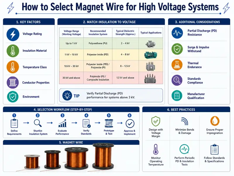
Core Insulation Challenges for High-Voltage Magnet Wire
Four types of issues coexist under high-voltage conditions—none can be omitted.
Partial Discharge (PD)
PD is virtually inevitable within windings at rated voltages >5.5 kV. Hazardous void or delamination thickness ranges from 0.1–0.6 mm—PD initiates whenever air-filled cavities or interfacial separations of this magnitude exist within the insulation film. PD does not cause immediate dielectric breakdown; instead, repeated bombardment of the enamel molecular chains by electrons and ions leads to electrical treeing, culminating in eventual breakdown—the entire process may span months to years.
Corona Effect
When the electric field strength exceeds the air breakdown threshold (~3 kV/mm), ambient air surrounding the conductor ionizes, emitting a faint violet glow and generating ozone. As a potent oxidant, ozone accelerates insulation aging. In variable-frequency drives (VFDs), high dv/dt pulses intensify corona activity; at elevated altitudes, reduced air density lowers the corona inception voltage by approximately 10–20% per 1 km increase in elevation.
Variable-Frequency Pulse Voltage (dv/dt)
VFD output PWM pulses exhibit rise times of 0.1–1 μs and peak voltages reaching 2–3× the rated voltage. This transient stress induces significantly greater “electrical aging” in enamel films compared to power-frequency operation, necessitating corona-resistant materials such as polyimide (PI) combined with nano-fillers.
Three Modes of Insulation Breakdown
- **Electrical Breakdown**: Instantaneous conduction occurs when applied voltage exceeds the enamel’s dielectric strength limit
- **Thermal Breakdown**: Excessive temperature causes enamel degradation, triggering a vicious cycle of increasing dielectric loss
- **Mechanical Breakdown**: Stress concentration induced by winding tension, thermal expansion, and vibration
In engineering practice, these three breakdown modes frequently occur simultaneously.
Insulation Material System Selection
High-voltage magnet wire enamel films must balance thermal class, dielectric strength, corona resistance, and cost:
| Material System | Thermal Class | Dielectric Strength | Corona Resistance | Typical Applications |
|---|---|---|---|---|
| PEW (Polyester) | B (130°C) | 30–60 kV/mm | Poor | Low-voltage motors, transformers |
| PEI (Polyester-imide) | F (155°C) | 40–80 kV/mm | Medium | High-voltage motor base layer |
| PAI (Polyamide-imide) | H (180°C) / N (200°C) | 50–100 kV/mm | Good | High-voltage topcoat, mechanical protection |
| PI (Polyimide) | N (200°C) / R (220°C) / 250°C | 60–200 kV/mm | Excellent | Traction, wind power, aerospace |
| Paper-wrapped (kraft paper) | A (105°C) | 10–20 kV/mm (multi-layer) | Excellent (after oil impregnation) | Power transformers |
| Glass-fiber wrapped | H (180°C) | 5–10 kV/mm (single-layer) | Good | Traction motors, dry-type transformers |
| Nomex paper-wrapped | N (200°C) / R (220°C) | 15–30 kV/mm | Excellent | Dry-type transformers, traction |
When single-material performance is insufficient, composite structures are employed: the three-layer structure of PEI + nano-filled layer + PAI is the mainstream solution for 5–15 kV motor windings. The three-component combination of primer + corona-resistant layer + topcoat is standard for most high-voltage magnet wires: the primer ensures adhesion, the topcoat provides mechanical and chemical protection, and the intermediate layer is specifically engineered to withstand partial discharge.
Enamel Coating Thickness (Grade) Selection
IEC 60317 and NEMA MW 1000 classify enamel coating thickness into three Grades:
| Grade | Enamel Thickness Increment | Breakdown Voltage (IEC Twist Test) | Breakdown Voltage (NEMA Twist Test) | Typical Applications |
|---|---|---|---|---|
| Grade 1 | Baseline | ≥1.4 kV | ≥2.4 kV | Low-voltage motors, standard transformers |
| Grade 2 | +30% | ≥2.8 kV | ≥4.8 kV | Preferred for high-voltage motors |
| Grade 3 | +60% | ≥4.2 kV | ≥7.2 kV | Special high-voltage and extra-high-voltage applications |
A higher Grade number indicates a thicker enamel coating and higher breakdown voltage; however, copper content ratio decreases and thermal dissipation deteriorates. Grade 2 is typically selected for high-voltage applications, while Grade 3 is used under extreme operating conditions. Note that IEC 60317 defines Grade based on percentage increment of enamel thickness, whereas NEMA MW 1000 defines Grade based on minimum breakdown voltage value. Always verify the applicable standard when reviewing specification sheets.
Thermal Class Matching with Motor / Transformer Insulation Systems
IEC 60085 classifies electrical insulation into nine temperature classes:
| Class | Maximum Temperature | Typical Materials | Typical Applications |
|---|---|---|---|
| Y | 90°C | Cotton, silk, unimpregnated | Nearly obsolete |
| A | 105°C | Oil-impregnated paper, varnished cambric | Legacy transformers |
| E | 120°C | Polyester resins, polyurethane | Small motors |
| B | 130°C | Mica, glass fiber + resin | Standard motors |
| F | 155°C | PEI, modified epoxy | Industrial high-voltage motors |
| H | 180°C | PAI, silicone, PI | Traction motors, wind power |
| N | 200°C | PI, specialty silicone rubber | Traction transformers, wind power generators |
| R | 220°C | Advanced PI, mica composites | High-speed rail traction, aerospace |
| 250 | 250°C | Ceramic-filled, mica board | Aerospace motors, specialty applications |
The standard thermal class for high-voltage equipment is Class F or H. Variable-frequency traction motors typically employ Class H (PI enamel + glass-fiber braid), while wind power generators commonly use Class H or N (PI or PAI). The thermal class of magnet wire is generally at least one class higher than that of the motor insulation system to ensure overall reliability.
Conductor Shape Selection
Conductor shape directly impacts slot fill factor, heat dissipation, and skin effect:
**Round Magnet Wire**
- Diameter range: AWG 14–50 (1.6–0.025 mm); typically AWG 14–24 (1.6–0.51 mm) for high-voltage applications
- Advantages: Mature winding process, low cost, high automation compatibility
- Disadvantages: Slot fill factor limited to ~78% maximum; pronounced skin effect
- Applications: Most medium- and low-voltage motors
**Rectangular / Flat Wire**
- Dimensions: Thickness 0.8–10 mm; Width 2–25 mm
- Advantages: Slot fill factor up to >90%; superior heat dissipation; high mechanical strength
- Disadvantages: Higher cost; electric field concentration at bend corners requires special design and processing
- Applications: High-voltage, high-capacity motors (>100 kW); high-current transformer windings
**Litz Wire**
- Construction: Multiple individually insulated fine strands twisted together (typical strand diameter ≤0.1 mm)
- Advantages: Effectively suppresses skin and proximity effects; reduces AC losses
- Disadvantages: Higher cost; lower space factor
- Applications: High-frequency, high-voltage applications (>10 kHz); induction heating; wireless charging
In high-voltage systems, round wire with Grade 2/3 insulation coating is the most common configuration; rectangular wire is used in high-voltage, high-capacity applications; Litz wire is applied in specialized high-frequency scenarios.
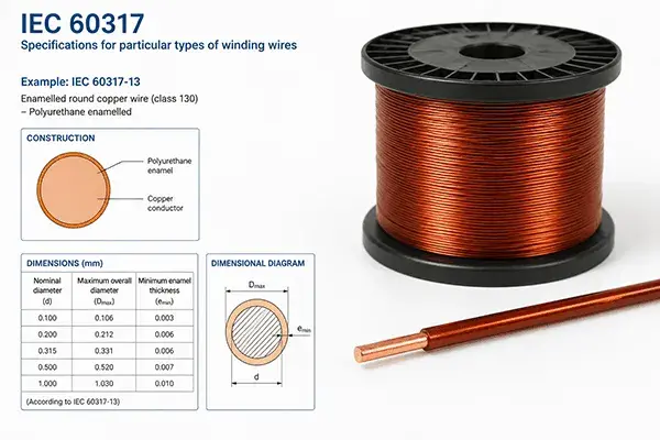
Distinction Between Breakdown Voltage and Dielectric Strength
These two parameters are often confused during product selection:
- **Breakdown Voltage**: Expressed in kV; the maximum voltage the enamel coating can withstand; test methods: IEC 60851-5 (Twist Test) and NEMA MW 1000 §3.5 (Twist Test)
- **Dielectric Strength**: Expressed in kV/mm; the electric field endurance capability of the enamel coating itself; test method: ASTM D149 (Flat-Plate Method)
Relationship between the two: Dielectric Strength ≈ Breakdown Voltage / Enamel Coating Thickness. For Grade 2 wire, with an enamel thickness of 30–60 μm and a breakdown voltage of 2.8 kV, the corresponding dielectric strength is approximately 47–93 kV/mm—consistent with the ASTM D149 measured range (30–200 kV/mm). In high-voltage applications, both breakdown voltage (to ensure compliance with voltage class requirements) and dielectric strength (to evaluate safety margin) must be evaluated during selection.
High-Voltage Equipment Classification and Typical Magnet Wire Configurations
| Equipment Type | Voltage Range | Typical Magnet Wire Configuration | Key Requirements |
|---|---|---|---|
| Distribution Transformers (10 kV) | 10/0.4 kV | Paper-wrapped round wire + transformer oil | Oil resistance, low cost, high insulation |
| Dry-Type Transformers | ≤35 kV | Class H Polyimide (PI) enamel + Nomex paper | Flame retardancy, low smoke, UL 1446 system certification |
| Power Transformers | 35–1000 kV | Paper-wrapped + oil-immersed, PI enamel | Basic Impulse Level (BIL) compliance |
| High-Voltage Motors (6 kV) | 6 kV | SBEMB (silk-film wrapped) + PI enamel | Turn-to-turn insulation, enhanced first-turn insulation |
| High-Voltage Motors (10 kV) | 10 kV | SBEFB (silk-film wrapped) + PI enamel | Enhanced turn-to-turn insulation, partial discharge (PD) resistance |
| Traction Motors | 1–3 kV VFD | PI enamel + glass-fiber wrapping | Pulse resistance, oil resistance, vibration resistance |
| Wind Turbine Generators | 690 V–13.8 kV | Corona-resistant PI + Vacuum Pressure Impregnation (VPI) | Corona resistance, long service life (20 years) |
| X-ray / CT Equipment | 100–150 kV | PI enamel + PTFE outer jacket | Ultra-high insulation, low outgassing |
| Laser Power Supplies | 20–50 kV | Silicone rubber wire / PTFE wire | High-frequency dielectric strength, flame retardancy |
| Radar Transmitters | 30–80 kV | PI enamel + silicone rubber / polyimide film | Pulse withstand capability, low dielectric loss |
When selecting magnet wire, follow the sequence: equipment type → voltage class → material combination for the most direct specification retrieval.
Key Tests and Certifications
**Electrical Tests**
- Breakdown Voltage: Twisted Pair Method (IEC 60851-5, NEMA MW 1000 §3.5)
- PDIV / PDEV (Partial Discharge Inception / Extinction Voltage): IEC 60034-18-41
- Dielectric Constant + tan δ (Loss Tangent): ASTM D150
- Insulation Resistance: IEC 60851-5 §5.4
- Impulse Withstand: IEC 60851-5 §5.6 (Mandatory for VFD applications)
**Mechanical Tests**
- Elongation: IEC 60851-3 §6 (Cu ≥25%, Al ≥15%)
- Tensile Strength: IEC 60851-3 §6 (Cu 220 MPa, Al 90 MPa)
- Abrasion Resistance: IEC 60851-3 §5 (Grade 2 coating ≥5.5 N reciprocating)
- Springback Angle: IEC 60851-3 §7
**Environmental Tests**
- Thermal Shock: IEC 60851-6 §3 (No cracking during winding at minimum thermal class temperature)
- Softening Breakdown: IEC 60851-6 §4 (Combined effect of temperature and voltage)
- Chemical Resistance: ISO 1817, ASTM D543
- Oil Resistance: ASTM D471 (For traction motor and transformer oil environments)
**System Certifications**
IEC 60317 (Magnet Wire Product Specification Series), NEMA MW 1000 (North American Magnet Wire Standard), UL 1446 (Dry-Type Transformer Insulation Systems), GB/T 6109 (Chinese National Standard for Magnet Wire), JIS C 3202 (Japanese Industrial Standard for Magnet Wire), ISO 9001 / IATF 16949 / IRIS (Quality Management Systems).
Procurement Recommendation: Require suppliers to provide batch test reports; PDIV / PDEV data are mandatory for critical components (e.g., magnet wire for high-voltage motors).
Five-Step Selection Method
**Step 1: Determine Voltage Class**
Specify rated voltage, peak voltage, and transient overvoltage. For VFD applications, use 2–3× the rated voltage as the reference.
**Step 2: Determine Thermal Class**
Confirm the motor/transformer insulation system class per nameplate or manual; the magnet wire thermal class shall be at least one class higher than that of the equipment.
**Step 3: Select Material Combination**
- General-purpose low-voltage motors: PEW or PEI single-layer
- High-voltage motors: PEI + nanofiller layer + PAI triple-layer
- Traction/wind-power motors: PI enamel + glass-fiber/silk film wrap
- Transformers: paper-wrapped + oil-immersed, or PI + Nomex (dry-type)
**Step 4: Determine Enamel Coating Thickness**
Grade 1 is used for low-voltage and standard applications; Grade 2 is the preferred choice for high-voltage applications; Grade 3 is applied in ultra-high-voltage and special applications.
**Step 5: Verification and Certification**
Dielectric breakdown voltage, PDIV / PDEV, impulse voltage endurance test; IEC 60317 / NEMA MW 1000 certification; supplier qualifications (ISO 9001 + product certifications).
Common Selection Errors
**Rated voltage equated with peak voltage**: Using standard enameled wire for a 380 V motor, ignoring that VFD-induced peak voltages can exceed 760 V and superimposed dv/dt pulses. Correct approach: Grade 2 + corona-resistant construction.
**Neglecting thermal class compatibility**: Employing Class H magnet wire in a Class B motor under the misconception that “a higher class is always better.” Class H magnet wire incurs higher cost and features a relatively rigid polyimide (PI) film; matching the wire’s thermal class to the motor’s rating is sufficient—over-engineering is unnecessary.
**Applying low-voltage standards to high-voltage magnet wire**: Testing 10 kV motor magnet wire per GB/T 6109.1. High-voltage magnet wire must comply with dedicated standards IEC 60317-0-8 and IEC 60317-48 series, plus additional PDIV / PDEV validation.
**Ignoring temperature derating**: Designing for breakdown voltage at room temperature while operating at 155°C. Breakdown voltage decreases by approximately 5–8% per 10°C rise in temperature.
**Prioritizing unit price over service life**: Focusing solely on procurement cost. Repair expenses and production downtime resulting from high-voltage magnet wire failure may exceed the wire’s original cost by tens of times.
**Overlooking environmental factors**: Using standard magnet wire in high-altitude applications. Corona inception voltage declines by ~10–20% per 1 km increase in elevation; enhanced enamel thickness or Vacuum Pressure Impregnation (VPI) processing is required.
Development Trends
**Widespread Adoption of Nanofiller Technology**: PI enamel + nanoscale Al₂O₃ or TiO₂ fillers have become the mainstream solution for traction motors and wind power applications. Nanofillers effectively trap free electrons and suppress partial discharge (PD) propagation, extending service life by 3–5×.
**Regulatory Drivers for Environmental Compliance**: RoHS 2.0, REACH, and WEEE regulations continue to impose increasingly stringent restrictions on raw materials; suppliers must provide formal compliance declarations.
**Smart Manufacturing and In-Line Inspection**: Modern magnet wire plants are commonly equipped with laser diameter measurement (accuracy ±0.001 mm), 100% in-line dielectric breakdown testing per station, 100% in-line PD testing for high-voltage magnet wire, and AI-powered quality traceability systems.
**New Energy Applications Driving Performance Demands**: Emerging applications—including 800 V high-voltage platforms for new-energy vehicles, 1500 V DC photovoltaic systems, 1500–3000 V high-voltage DC energy storage systems, and 25 kV AC traction for high-speed rail—impose higher requirements on magnet wire voltage class, PD resistance, and thermal cycling performance.
**Turnkey Solutions**: Customers’ focus has shifted from single magnet wire supply to comprehensive insulation systems (enamel + wrapping + impregnating varnish), system-level certifications (UL 1446, IEC 60034 / IEC 60076), engineering support (electromagnetic, thermal, and mechanical simulation), and long-life commitments (20 years for wind power, 30 years for traction).
Conclusion
Core principles for high-voltage magnet wire selection:
**From a voltage perspective**, the rated voltage serves only as a reference; the actual enamel coating thickness is determined by peak voltage, transient overvoltage, and partial discharge inception voltage (PDIV). For variable-frequency drive (VFD) applications, magnet wire must be selected based on 2–3× the rated voltage.
**From a material perspective**, the three-layer structure of PEI + nanofiller layer + PAI is the mainstream solution for motor windings operating at 5–15 kV; PI enamel combined with glass-fiber or silk film wrapping is the standard configuration for traction and wind-power applications; paper wrapping plus oil impregnation remains the proven choice for large power transformers.
**From a process perspective**, implementing the five-step methodology—“voltage class → thermal class matching → material combination → enamel coating thickness → verification & certification”—avoids the vast majority of selection pitfalls. Supplier evaluation criteria include: qualifications (ISO 9001 + IEC/NEMA certifications), test reports (PDIV/PDEV, dielectric breakdown voltage), and industry experience (case references in wind power, traction, and medical applications).
High-voltage magnet wire selection is fundamentally a balance among voltage capability, temperature rating, service life, and cost. A thorough understanding of underlying principles, mastery of applicable standards (e.g., IEC 60317, NEMA MW 1000, IEC 60034-18-41, IEC 60076, IEC 60851, IEC 60085, ASTM D149, ASTM D150, UL 1446, GB/T 6109, JIS C 3202), and strict adherence to procedural rigor are all indispensable.