


Industrial Context and Identification Requirements for Enamel-Coated Copper Wire and Enamel-Coated Aluminum Wire
Enamel-coated copper wire (copper magnet wire) and enamel-coated aluminum wire (aluminum magnet wire) both belong to the broad family of magnet wire (also known as winding wire), serving as core winding materials in electromagnetic energy conversion and transmission devices—including motors, transformers, inductors, household appliances, and traction motors for new-energy vehicles. Enamel-coated copper wire has long dominated the global magnet wire market, accounting for approximately 75%–80% of total volume, primarily due to its superior electrical conductivity, high mechanical strength, and excellent solderability. Although enamel-coated aluminum wire holds a comparatively smaller market share (approximately 15%–20%), its significant advantages in weight reduction and cost efficiency render it indispensable in applications such as distribution transformers, low-voltage motors, household appliances, induction heating systems, reactors, energy-storage inductors, and lightweight windings.
In recent years, periodic fluctuations in copper prices (LME copper: USD 8,000–10,000 per metric ton) and aluminum prices (LME aluminum: USD 2,200–2,600 per metric ton), coupled with rapid growth in emerging markets—including new-energy vehicles, wind power, photovoltaics, energy storage, and 5G base stations—have spurred the proliferation of alternative or hybrid solutions such as enamel-coated aluminum wire, copper-clad aluminum (CCA) wire, and enameled copper-clad aluminum (ECCA) wire. Across the magnet wire supply chain—including manufacturers, winding houses, end users, testing laboratories, traders, and recycling enterprises—the demand for accurate, rapid, repeatable, and low-cost identification of conductor material in enamel-coated wires has surged dramatically. This need arises at multiple stages: raw-material procurement, incoming quality control (IQC), outgoing quality control (OQC), type testing, dispute resolution for returns, customs declaration, secondary sales, and engineering design selection.
However, accurate identification remains challenging. Factors such as the insulating enamel coating obscuring the underlying conductor, the deceptive appearance of the copper-plated surface on CCA wire, visual confusion caused by copper- or tin-plating on aluminum wire, differences in luster between annealed and hard-drawn states, color distortion induced by dyed enamel, and formation of surface oxide layers collectively reduce the accuracy of visual inspection or single-method identification to often less than 60%. Moreover, misidentification may lead to severe engineering consequences: substituting copper wire for aluminum wire in motors or transformers results in significantly increased costs and loss of competitive advantage; conversely, misidentifying aluminum wire as copper wire leads to higher resistance, excessive temperature rise, reduced efficiency, shortened service life, and even catastrophic burnout. Therefore, systematic mastery of reliable differentiation methods among copper wire, aluminum wire, and copper-clad aluminum wire (CCA/ECCA) is an essential competency for professionals across the magnet wire industry.
Systematic Differences in Physical Properties Between Copper and Aluminum Wires
Copper and aluminum—two dominant conductor materials for electromagnetic wires—exhibit systematic differences across physical, chemical, electrical, thermal, and mechanical properties. These differences serve both as the basis for engineering material selection and as the physical foundation for material identification.
Regarding density, pure copper (grades C11000 ETP / C10100 OFHC / C10200 OF / C12200 DHP) has a density of 8.89–8.96 g/cm³, whereas pure aluminum (grades 1050-O / 1060 / 1070 / 1100 / 1350-O / 1370) exhibits a density of 2.69–2.71 g/cm³—approximately 3.32 times lower than that of copper. Consequently, for enameled wires of identical length and cross-sectional area, copper wire weighs roughly 3.32 times more than aluminum wire—a critical factor for tactile assessment and precision balance measurements used in routine identification. Copper-clad aluminum (CCA) wire exhibits an intermediate density, varying linearly from approximately 3.0 g/cm³ to ~5.0 g/cm³ depending on the copper layer thickness (10%, 15%, 20%, 30%, or 40% by volume).
In terms of electrical properties, according to the International Annealed Copper Standard (IACS), pure copper achieves 100% IACS conductivity, with a volumetric resistivity of 1.724 μΩ·cm at 20°C; pure aluminum achieves 61% IACS conductivity, with a volumetric resistivity of 2.654 μΩ·cm. Thus, at equal cross-sectional area, copper wire exhibits approximately 65% of the resistance of aluminum wire and offers ~53% higher current-carrying capacity. Although aluminum’s lower conductivity is a disadvantage, its significantly lower density confers a key advantage: under equal mass conditions, aluminum wire can provide up to 2.5 times the conductive cross-sectional area of copper wire, resulting in superior specific conductivity (conductivity per unit mass). This characteristic constitutes the fundamental rationale for selecting aluminum wire in lightweight windings for aerospace, aviation, new-energy vehicles, and wind-power generation.
Thermally, pure copper exhibits a thermal conductivity of 401 W/m·K, while pure aluminum exhibits 237 W/m·K—copper thus demonstrates ~70% better heat dissipation performance. Under identical current density, copper windings exhibit markedly lower temperature rise than aluminum windings—a critical consideration for thermal management design in high-power-density motors (e.g., traction motors for new-energy vehicles and direct-drive wind-turbine generators). The melting points of copper and aluminum are 1085°C and 660°C, respectively; consequently, copper windings possess substantially greater short-circuit withstand capability. With respect to coefficient of thermal expansion (CTE), copper exhibits 16.5 ppm/°C versus aluminum’s 23.1 ppm/°C—aluminum windings therefore demonstrate relatively poorer dimensional stability, necessitating larger assembly clearances under thermal cycling conditions.
Mechanically, annealed pure copper exhibits tensile strength of 210–220 MPa and elongation ≥30%; annealed pure aluminum exhibits tensile strength of 70–90 MPa and elongation ≥25%. Hard-drawn copper wire (half-hard H02 / full-hard H04) achieves tensile strengths of 350–450 MPa, while hard-drawn aluminum wire (H14 / H18) reaches 100–200 MPa. Copper’s superior mechanical strength renders it especially suitable for high-speed automated winding processes, significantly reducing breakage rates during winding.
Chemically, copper forms red cuprous oxide (Cu₂O) and black cupric oxide (CuO) at ambient temperature; in humid, CO₂-containing environments, it further develops green basic copper carbonate (Cu₂(OH)₂CO₃, commonly known as patina or verdigris). Aluminum, conversely, rapidly forms a dense, protective aluminum oxide (Al₂O₃) film at room temperature, typically 2–10 nm thick, which effectively inhibits further oxidation. However, this oxide layer is susceptible to corrosion in acidic or alkaline environments.
Magnetically, copper is diamagnetic, whereas aluminum is paramagnetic; neither exhibits ferromagnetism detectable by conventional permanent magnets (e.g., NdFeB grades N35–N52). Consequently, magnetic testing serves only to exclude ferromagnetic contaminants and cannot distinguish between copper and aluminum.
Visual Inspection and Sensory Identification Methods
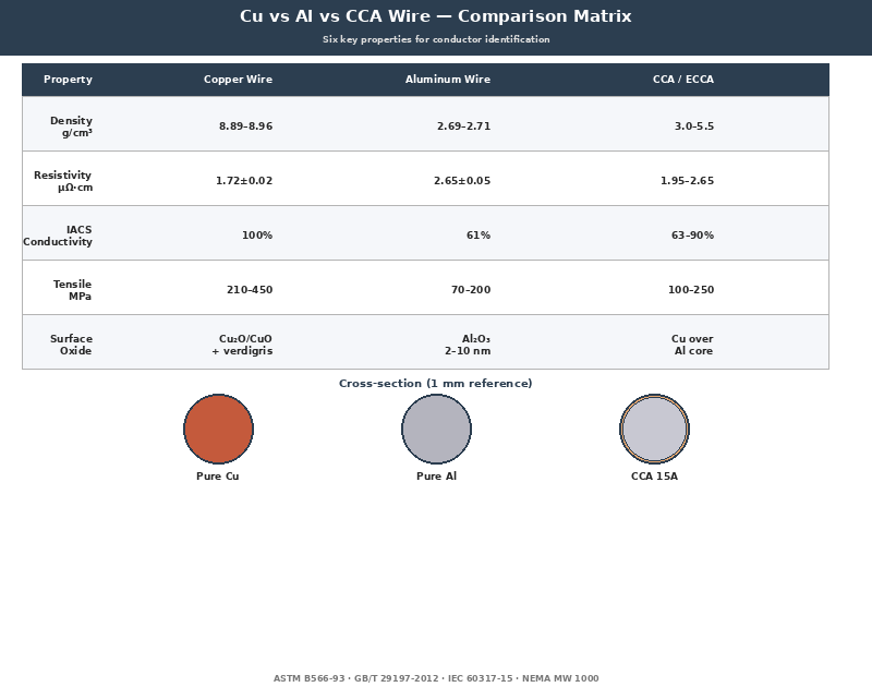
Visual inspection is the most fundamental, rapid, and cost-effective first step in identifying the conductor material of enameled wire; however, its accuracy can only be improved by combining it with experience and multiple auxiliary techniques.
Conductor Color:
Copper wire exhibits a characteristic reddish-brown to orange-red metallic luster (commonly referred to as “copper-red”); even after annealing, it retains this warm hue. As-drawn (hard-drawn) copper wire displays an orange-red metallic luster on its surface, whereas annealed (soft-drawn) copper wire appears purplish-red with slightly reduced luster. As-drawn aluminum wire exhibits a bright silvery-white metallic luster, while annealed (soft-drawn) aluminum wire appears silvery-gray with diminished luster.
Oxidation State:
When exposed to air over extended periods, copper wire gradually forms a surface oxide layer ranging from dark red to brown-black or even black (CuO). Under humid conditions, it further develops green basic copper carbonate (verdigris / patina), commonly known as “copper green.” In contrast, aluminum wire rapidly forms a dense, grayish-white aluminum oxide (Al₂O₃) film on its surface; further oxidation results in a dark-gray appearance. The marked color differences between these oxidation products can serve as an initial basis for differentiation. However, caution is warranted: tinned copper wire exhibits a silvery-white surface appearance, closely resembling aluminum wire—thus requiring verification via subsequent analytical methods.
Insulation Enamel Color:
The insulation enamel coating on enameled wire typically appears light yellow, amber, brown, red, dark brown, or even black, depending on the resin type (e.g., polyester, polyurethane, polyester-imide, polyamide-imide, polyimide) and pigment formulation. Importantly, enamel color bears no direct correlation to the underlying conductor material and therefore cannot be used to determine conductor composition.
Tactile Sensation and Weight:
For identical diameter (e.g., 1.0 mm) and length (e.g., 1 m), enameled copper wire weighs approximately 8.96 g, whereas enameled aluminum wire weighs approximately 2.70 g—a difference readily perceptible by hand. Even experienced operators may misidentify short samples (50–100 mm in length); therefore, precise weighing using an electronic balance (with resolution of 0.01 g or better) is recommended.
Limitations of Visual Inspection:
Relying solely on visual observation and tactile assessment yields an identification accuracy of only ~60–75%. For surface-treated wires—including tinned copper, nickel-plated copper, silver-plated copper, and copper-clad aluminum (CCA, with a copper outer layer)—visual inspection is highly prone to misidentification. Consequently, comprehensive identification must integrate supplementary techniques such as magnetic testing, density measurement, electrical resistivity analysis, X-ray fluorescence (XRF) spectroscopy, and metallographic examination.
Magnetic Testing and Preliminary Screening
Magnetic testing is a rapid exclusion method based on differences in material magnetism, primarily used to identify ferromagnetic impurities—not to distinguish between copper and aluminum.
Neodymium-iron-boron (NdFeB) permanent magnets (recommended grade N35 or higher) are the most commonly used tool for electromagnetic wire identification. During testing, the magnet is slowly brought close to the enameled wire sample surface to a distance of approximately 1–3 mm, and attraction is observed. Pure copper and pure aluminum are both non-ferromagnetic; thus, neither will be attracted by the magnet. Similarly, for coils wound from enameled wire—where the large number of turns renders the enamel coating and air gaps effectively non-magnetic—the magnet will also produce no attraction.
If the sample exhibits clear attraction to the magnet, this strongly suggests the conductor may contain ferromagnetic components. Common scenarios include:
- The conductor itself is steel or iron (to be excluded);
- The conductor is copper-plated steel (not permitted under electromagnetic wire standards);
- The conductor is an iron-containing alloy (e.g., Cu–Fe alloy—beyond the scope of this document);
- The sample is contaminated with iron filings, steel particles, or other magnetic inclusions.
Limitations of magnetic testing: Magnetic testing can only exclude ferromagnetic materials; it is ineffective for distinguishing between non-ferromagnetic materials such as copper vs. aluminum, copper vs. copper-clad aluminum (CCA), or aluminum vs. CCA. The relative magnetic permeabilities of copper and aluminum are both very close to 1 (copper ≈ 0.99999; aluminum ≈ 1.000022), making differentiation even with high-sensitivity fluxmeters extremely difficult. Therefore, magnetic testing serves only as a preliminary screening tool and must be supplemented by further analytical methods—including density measurement, electrical resistivity testing, X-ray fluorescence (XRF) spectroscopy, and metallographic analysis—for definitive identification.
Density Measurement and Identification
Density measurement is a classical identification method based on Archimedes’ principle. It offers the advantages of non-destructiveness, high accuracy (error < 0.5%), simple equipment, and ease of operation—making it one of the most commonly used methods in both laboratory and production environments.
Test equipment includes: an electronic balance with a precision of 0.01 g or 0.001 g; a fine metal-wire basket for the Archimedean method; a thermometer for measuring water temperature (precision ±0.5°C); and distilled or deionized water.
Test procedure:
Step 1: Measure the mass of the specimen in air (m_air), accurate to 0.01 g.
Step 2: Place the specimen into the basket and fully immerse it in distilled water at 20–25°C, ensuring complete submersion and absence of adhering air bubbles; then measure the mass of the specimen in water (m_water).
Step 3: Calculate density using the formula:
ρ = m_air / (m_air − m_water) × ρ_water,
where ρ_water denotes the density of water at the measured temperature (0.9982 g/cm³ at 20°C; 0.9970 g/cm³ at 25°C).
Identification criteria:
- Pure copper: 8.89–8.96 g/cm³
- Pure aluminum: 2.69–2.71 g/cm³
- Copper-clad aluminum (CCA) wire (10A / 10H): ~3.0–3.2 g/cm³
- CCA wire (15A / 15H): ~3.4–3.7 g/cm³
- CCA wire (20A / 20H): ~3.9–4.2 g/cm³
- CCA wire (30A): ~4.6–4.8 g/cm³
- CCA wire (40A): ~5.2–5.5 g/cm³
Note the precision limitations of density-based identification: For CCA, the typical tolerance on copper-layer thickness is ±10%, and density measurements are thus susceptible to variations in copper-layer thickness. While density measurement serves well as a rapid classification tool, it cannot replace the metallurgical (metallographic) method—specified in GB/T 29197–2012 as the arbitration method—for definitive accuracy. Therefore, it is recommended to adopt a comprehensive assessment combining resistivity measurement, X-ray fluorescence (XRF) elemental analysis, and other complementary techniques.
For enameled wires with small diameters (e.g., 0.10–0.30 mm), the mass of a single specimen is only approximately 0.01–0.20 g, resulting in relatively large density measurement errors. To improve accuracy, it is recommended either to combine multiple specimens (e.g., 5–10 segments, each 1 m long) for collective measurement, or to determine resistivity via the four-wire resistance method combined with length and cross-sectional area measurements—and then perform dual-criteria evaluation based on both density and resistivity.
Electrical Property Measurement Identification
Electrical property measurement is a non-destructive identification method based on the difference in resistivity between copper and aluminum (Cu: 1.724 μΩ·cm vs. Al: 2.654 μΩ·cm—a difference of approximately 1.54×). It offers high accuracy, excellent repeatability, and suitability for automated online inspection, and is one of the standard methods for factory acceptance testing of electromagnetic wires.
Test equipment includes:
- Four-wire micro-ohmmeter (e.g., KEITHLEY DMM6500, HIOKI RM3545, or CHROMA 16502; accuracy: 0.1 μΩ);
- Constant-temperature water bath (20°C ± 0.5°C);
- Precision micrometer or laser diameter gauge (accuracy: 0.001 mm);
- Precision ruler or laser length gauge (accuracy: 0.5 mm).
Test procedure:
Step 1: Measure the length (L) of the enameled wire sample; recommended sample length is 1.000 m ± 0.001 m.
Step 2: Use the micrometer to measure the total outer diameter of the enameled wire (including the enamel coating). Then, locally remove ~10 mm of enamel using acetone or isopropanol, and measure the bare conductor diameter (d).
Step 3: Calculate the conductor cross-sectional area (A) using the formula A = π × d² / 4.
Step 4: Measure the sample resistance (R) using the four-wire micro-ohmmeter, with current applied parallel to the sample length direction; select current magnitude such that the resulting voltage drop falls within the range of 10–100 mV.
Step 5: Calculate the resistivity (ρ) using the formula ρ = R × A / L, with required accuracy of 0.01 μΩ·cm.
Acceptance criteria:
- Copper conductors at 20°C: resistivity shall be 1.72 ± 0.02 μΩ·cm (i.e., 1.70–1.74 μΩ·cm);
- Aluminum conductors at 20°C: resistivity shall be 2.65 ± 0.05 μΩ·cm (i.e., 2.60–2.70 μΩ·cm);
- Copper-clad aluminum (CCA) resistivity lies between these two values:
- 10A grade: ~2.55–2.65 μΩ·cm,
- 15A grade: ~2.45–2.55 μΩ·cm,
- 20A grade: ~2.35–2.45 μΩ·cm,
- 30A grade: ~2.15–2.25 μΩ·cm,
- 40A grade: ~1.95–2.05 μΩ·cm.
Temperature correction: Resistivity varies with temperature. It is recommended to maintain the sample temperature at 20°C ± 0.5°C during measurement; alternatively, apply the temperature-correction formula:
ρ(T) = ρ(20°C) × [1 + α × (T − 20)],
where the temperature coefficient α = 0.00393 /°C for copper and α = 0.00403 /°C for aluminum.
Limitations of the resistivity method:
Resistivity measurement requires knowledge of the conductor’s cross-sectional area. For conductors with irregular cross-sections—such as flat wire, shaped wire, embossed wire, or stranded wire—the measurement error increases significantly. For CCA, due to the ±10% tolerance in copper-cladding thickness, measured resistivity may deviate from the theoretical value by 5–10%. Therefore, comprehensive judgment should combine resistivity measurements with density determination and X-ray fluorescence (XRF) analysis.
XRF and Eddy Current Non-Destructive Testing
XRF (X-Ray Fluorescence) and eddy current testing are two modern, non-destructive identification techniques characterized by rapidity, accuracy, and compatibility with online integration. They are now widely employed in the electromagnetic wire industry for incoming material inspection and final product verification.
XRF Detection Principle: An XRF analyzer emits high-energy X-rays or γ-rays onto the sample surface, thereby exciting characteristic X-ray fluorescence from elements present in the sample. Each element emits fluorescence at a unique characteristic energy; by detecting both the energy and intensity of these characteristic X-rays, quantitative analysis of elemental composition is achieved. XRF instruments achieve an accuracy of up to 99.9%, capable of detecting nearly all elements in the periodic table with atomic number ≥ 4 (i.e., beryllium and above). Typical measurement time ranges from 1 to 30 seconds.
Application of XRF in Enameled Wire Identification: Handheld XRF analyzers (e.g., Hitachi X-MET8000, Thermo Fisher Niton XL2, Olympus Vanta) enable non-destructive elemental analysis of the enameled wire surface. For samples with thin insulation coatings—such as polyester-based enamel films (thickness: 20–50 μm)—X-rays penetrate the coating (typical X-ray penetration depth: hundreds of micrometers to several millimeters), allowing direct measurement of elemental composition at the conductor surface. For thicker insulation layers—such as polyimide enamel films (50–100 μm)—localized removal of the enamel layer is required prior to analysis. XRF provides direct readouts of elemental percentages—including Cu%, Al%, Fe%, Ni%, Sn%, Ag%, and Zn%—enabling accurate differentiation among various conductor materials, such as pure copper, pure aluminum, tin-plated copper, nickel-plated copper, and copper-clad aluminum (CCA).
Limitations of XRF: XRF exhibits low sensitivity toward light elements (e.g., Li, Be, B, C) and is essentially incapable of detecting elements with atomic number < 11 (i.e., sodium and below). Furthermore, XRF measures only surface elemental composition; for samples with thick surface platings (e.g., Sn or Ni plating > 5 μm), the underlying substrate composition may not be detectable, necessitating complementary analytical methods.
Eddy Current Detection Principle: Eddy current testing operates on the principle of electromagnetic induction: a high-frequency alternating magnetic field induces circulating eddy currents within a conductive material (e.g., coil or wire). The distribution and magnitude of these eddy currents depend on the conductor’s electrical conductivity, magnetic permeability, geometric configuration, and surface condition. Differences in eddy current response—including impedance, phase angle, and resonant frequency—are detected and analyzed to distinguish among different conductor materials, such as copper, aluminum, and CCA.
Application of Eddy Current Testing in Enameled Wire Identification: Commercial eddy current flaw detectors (e.g., Förster Defectomat, Olympus NORTEC 600, ETher NDC) simultaneously assess multiple parameters—including enamel continuity, conductor material identity, and surface defects. The eddy current response to copper versus aluminum differs markedly (copper conductivity = 100% IACS vs. aluminum = 61% IACS; a difference of ~39%), enabling high-speed, inline sorting at production line speeds of 100–500 m/min.
Limitations of Eddy Current Testing: Eddy current responses are highly sensitive to variations in surface condition—including surface roughness, oxide layers, and enamel thickness—requiring regular recalibration using reference standards. Moreover, precise quantification of the copper cladding thickness in CCA wire remains challenging; thus, eddy current testing is typically used as a rapid classification tool rather than a precision metrology method.
Paint Film Removal and Cross-Sectional Metallographic Analysis
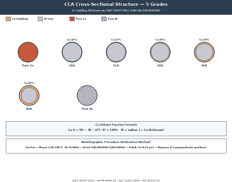
Paint film removal and cross-sectional metallographic analysis constitute micro-destructive identification methods and serve as the arbitration method for determining the copper layer thickness of copper-clad aluminum (CCA) wire, as specified in GB/T 29197–2012.
Paint Film Removal Methods:
- Chemical method: Immersion in concentrated sulfuric acid (98% H₂SO₄) or concentrated hydrochloric acid (37% HCl) at 60–80 °C for 10–30 minutes dissolves the paint film. This method is suitable for large-volume sample batches but requires proper waste liquid disposal.
- Mechanical method: Localized removal of the paint film over a length of 10–30 mm using fine-grit sandpaper (400–1000 mesh) or a razor blade. This method is operationally simple and suitable for rapid on-site inspection.
- Thermal decomposition method: High-temperature incineration at 400–500 °C for 5–10 minutes carbonizes and removes the paint film.
After paint film removal, visually inspect or examine under a 10× magnifier the conductor’s surface color: pure copper appears reddish-brown to orange-red; pure aluminum appears silvery-white to grayish-silver; for CCA wire, the underlying aluminum core exhibits a silvery-white appearance once the outer copper cladding is removed.
Cross-Sectional Metallographic Analysis Procedure:
- Sample sectioning: Cut a specimen 10–20 mm in length and mount it using epoxy resin or hot-compression mounting powder at a temperature of 150–180 °C and pressure of 20–30 MPa.
- Grinding: Sequentially grind the mounted specimen with silicon carbide abrasive papers of increasing fineness—200, 400, 800, 1200, and 2000 mesh—rotating the specimen by 90° between each grit stage.
- Polishing: Polish on a cloth using diamond polishing paste (particle sizes 1 μm and then 0.25 μm) until a mirror-like finish is achieved.
- Thickness measurement: Measure the copper layer thickness—including the thinnest location—at four mutually perpendicular positions using either a measuring microscope (resolution 0.001 mm) or a metallographic microscope (magnifications 100×–500×).
- Volume ratio calculation: Compute the copper volume fraction as:
\[
\text{Copper volume fraction} = \frac{R^2 – (R – t)^2}{R^2} \times 100\%,
\]
where \(R\) is the conductor radius and \(t\) is the measured copper layer thickness.
Metallographic Analysis Acceptance Criteria:
According to GB/T 29197–2012 and ASTM B566, CCA wire is classified into three grades: 10A/10H, 15A/15H, and 20A/20H, corresponding to nominal copper volume fractions of 10% ± 2%, 15% ± 2%, and 20% ± 2%, respectively. Per industry standard SJ/T 11223–2000, the copper layer thickness shall fall within the range of 0.05–0.30 mm. Metallographic analysis serves as the arbitration method: it yields highly accurate results but is time-consuming (1–2 hours per specimen), making it appropriate for type testing and dispute resolution.
Chemical Testing and Flame Testing
Chemical testing and flame testing are classical, on-site rapid identification methods—simple to perform and low in cost—but their accuracy and safety are limited; therefore, they are recommended only as auxiliary techniques.
Dilute Nitric Acid Test Method:
Using a cotton swab, apply a 10% dilute nitric acid (HNO₃) solution to the conductor surface after removing the paint coating, and observe the reaction and resulting solution color. Pure copper dissolves rapidly, and the solution gradually turns bluish-green (characteristic of Cu²⁺ ions). The reaction equation is:
3 Cu + 8 HNO₃ (dilute) → 3 Cu(NO₃)₂ + 2 NO↑ + 4 H₂O.
Pure aluminum dissolves slowly in dilute nitric acid, yielding a nearly colorless solution (Al³⁺ ions are colorless). The reaction equation is:
Al + 4 HNO₃ (dilute) → Al(NO₃)₃ + NO↑ + 2 H₂O; however, the actual reaction proceeds very slowly. In Copper-Clad Aluminum (CCA), dissolution of the surface copper plating reveals the underlying aluminum core.
Precautions for the Dilute Nitric Acid Test:
Testing must be conducted inside a fume hood. Operators must wear safety goggles, rubber gloves, and a lab coat. Concentrated nitric acid (>65%) generates toxic, reddish-brown nitrogen dioxide (NO₂) gas and must be avoided. Post-test samples and waste solutions must be disposed of in accordance with hazardous chemical handling regulations.
Flame Test Method:
Heat the bare (paint-free) end of the conductor to red-hot temperature (~700–900 °C) using a propane torch or butane lighter, and observe flame characteristics and oxidation behavior. Pure copper forms a black copper(II) oxide (CuO) layer on its surface upon heating in air, with essentially no visible change in flame color. Pure aluminum rapidly forms a white aluminum oxide (Al₂O₃) layer on its surface when heated in air; further heating thickens this oxide layer, yet the flame remains largely unchanged in color. In CCA, oxidation of the surface copper plating exposes the silvery-white aluminum core underneath.
Limitations of the Flame Test:
The flame test is a qualitative method capable only of distinguishing broad metal categories—not of precisely determining the copper-layer thickness ratio in CCA. Due to the high heating temperatures involved, it poses operational safety hazards and causes irreversible sample damage; thus, it is suitable only for rapid verification of small samples.
Copper-Clad Aluminum Wire (CCA/ECCA) Identification Special Topic
Copper-clad aluminum wire (CCA) and enameled copper-clad aluminum wire (ECCA) are rapidly developing composite conductor materials. They are primarily used in high-frequency inductors, coaxial cables for 5G base stations, lightweight windings for new-energy vehicles, and lightweight transformer and inductor designs. Their identification methods differ significantly from those for pure copper or pure aluminum wires and require special attention to three core parameters: copper-layer thickness, copper-to-aluminum volume ratio, and interfacial bond strength.
Structural characteristics of CCA: A solid aluminum core—typically from the commercially pure aluminum series (e.g., 1050, 1060, or 1100)—is continuously clad with a layer of oxygen-free copper (OFC, ASTM C10100) or electrolytic-tough-pitch (ETP) copper (ASTM C11000). The copper cladding is formed via metallurgical bonding (e.g., continuous casting or cladding-welding processes) or electroplating, resulting in a permanent bond. Common copper-volume ratios are 10%, 15%, and 20%, with copper-layer thickness tolerances of ±10%.
Key identification methods for CCA:
- Metallographic method (arbitration method): A cross-sectional sample is cut, mounted, ground, and polished; copper-layer thickness and copper-volume ratio are then measured using a measuring microscope.
- Density method (rapid method): Density is measured experimentally and compared against a theoretical density–copper-volume-ratio reference table: a 10% copper volume ratio corresponds to a density of ~3.0–3.2 g/cm³; 15%, to 3.4–3.7 g/cm³; and 20%, to 3.9–4.2 g/cm³.
- XRF method (non-destructive method): A handheld X-ray fluorescence (XRF) spectrometer directly measures Cu% and Al% content, enabling identification of the composite structure (i.e., plating vs. substrate).
- Resistivity method (indirect method): Electrical resistivity is measured and cross-verified against a reference table correlating resistivity with known copper-volume ratios.
Special considerations for ECCA identification: ECCA adds an insulating enamel coating onto the CCA substrate. Prior to identification, the enamel must first be removed—either chemically or mechanically—after which standard CCA identification procedures apply. Particular attention must be paid to interfacial bond strength among the enamel layer, copper cladding, and aluminum core. Bond integrity may be assessed by repeated bending (five to ten 90° bends), observing for signs such as copper-layer delamination, enamel cracking, or exposure of the aluminum core.
Standards applicable to CCA/ECCA:
- ASTM B566-93 (American Society for Testing and Materials: Standard Specification for Copper-Clad Aluminum Wire)
- GB/T 29197–2012 (Chinese National Standard: Copper-Clad Aluminum Wire, including Classes 10A, 10H, 15A, 15H, 20A, and 20H)
- SJ/T 11223–2000 (Chinese Electronic Industry Standard: Copper-Clad Aluminum Wire)
- IEC 60317-15 (International Electrotechnical Commission: Specifications for Enameled Round Copper-Clad Aluminum Wire)
- NEMA MW 1000 (National Electrical Manufacturers Association: Specifications for Enameled Copper-Clad Aluminum Wire)
- JIS C 3202 (Japanese Industrial Standard)
- GB/T 6109.15–2008 (Chinese National Standard: Enameled Round Copper-Clad Aluminum Wire)
Industrial-Grade QC Sampling and Standard System
Industrial-grade quality control (QC) sampling plans are a critical component for ensuring that magnet wire conductor materials comply with technical specifications, requiring the establishment of a systematic process covering sampling, testing, acceptance/rejection decisions, and traceability.
The primary sampling standard is GB/T 2828.1–2012 (identical to ISO 2859-1:1999), a counting-based sampling standard. General Inspection Level II is commonly adopted in the magnet wire industry; Special Inspection Levels S-1 through S-4 are applied for destructive or high-cost tests. The relationship between lot size and sample size is as follows:
- Lot size 26–50 units (boxes/coils): sample size = 8 units
- Lot size 51–90 units: sample size = 13 units
- Lot size 91–150 units: sample size = 20 units
- Lot size 151–280 units: sample size = 32 units
- Lot size 281–500 units: sample size = 50 units
- Lot size 501–1,200 units: sample size = 80 units
- Lot size 1,201–3,200 units: sample size = 125 units
- Lot size 3,201–10,000 units: sample size = 200 units
Acceptable Quality Limit (AQL) setting: Conductor material identification for magnet wire constitutes a critical quality characteristic; an AQL of 0.65 is recommended (i.e., no more than 0.65 defects per 100 units is acceptable). For enameled copper wire key parameters:
- Copper content ≥ 99.90% (C11000)
- Resistivity = 1.72 ± 0.02 μΩ·cm
- Density = 8.89–8.96 g/cm³
- Tensile strength = 210–450 MPa
- Elongation ≥ 30%
- Enamel coating continuity: compliant
For enameled aluminum wire key parameters:
- Aluminum content ≥ 99.50% (Alloys 1050/1060)
- Resistivity = 2.65 ± 0.05 μΩ·cm
- Density = 2.69–2.71 g/cm³
- Tensile strength = 70–200 MPa
- Elongation ≥ 25%
- Enamel coating continuity: compliant
Comprehensive Standard System:
- International Standards: IEC 60317-0-1 (General requirements for enamelled round winding wires), IEC 60317-15 (Enamelled copper-clad aluminium round winding wires), IEC 60317-25 (Enamelled aluminium round winding wires), IEC 60317-27 (Paper-covered copper rectangular winding wires), IEC 60317-46 (Class 200 enamelled round copper winding wires), IEC 60851 (Test methods for enamelled winding wires), IEC 60243 (Methods of test for electric strength of solid insulating materials), ASTM B566 (Standard Specification for Aluminium-Clad Copper Wire), ASTM B3 (Standard Specification for Soft or Annealed Copper Wire), ASTM B8 (Standard Specification for Concentric-Lay-Stranded Copper Conductors), ASTM B230/B231 (Standard Specification for Aluminum 1350 Conductors), ASTM B193 (Standard Test Method for Resistivity of Electrical Conductor Materials), ASTM B279 (Standard Test Method for Magnetic Properties of Electrical Steels);
- Chinese National Standards: GB/T 6109.1–6109.23 (Series of standards for enameled round copper winding wires), GB/T 7095.1–7095.7 (Series of standards for enameled rectangular copper winding wires), GB/T 29197–2012 (Aluminum-clad copper wire), GB/T 3953 (Round copper wire for electrical purposes), GB/T 3955 (Round aluminum wire for electrical purposes), GB/T 5584.1–4 (Round copper rods for electrical purposes), SJ/T 11223–2000 (Aluminum-clad copper wire), GB/T 3048 (Electrical test methods for electric cables and wires);
- European Standards: EN 60317 (identical to IEC 60317 series), EN 60228 (Conductors of insulated cables), EN 13602 (Copper and copper alloys — Drawn solid round wire), EN 13605 (Copper and copper alloys — Rods, bars and sections);
- Japanese Industrial Standards: JIS C 3202 (Enameled wires), JIS C 3210–3212 (Various types of insulated electromagnetic wires), JIS C 3102 (Round copper wire for electrical purposes);
- U.S. Standards: NEMA MW 1000 (Comprehensive standard for enameled wires, including MW 18, MW 35, MW 41–44, MW 46, MW 48, MW 53, MW 62, etc.), UL 1446 (Standard for Systems of Insulating Materials).
Recommended Testing Equipment Configuration:
- Basic Level (small- and medium-sized enterprises): electronic balance (0.001 g resolution), four-wire milliohmmeter, enamel continuity tester (DC 30–1500 V), calipers, and micrometers;
- Intermediate Level (large enterprises): in addition to basic-level equipment, add X-ray fluorescence (XRF) analyzer, density measurement kit, metallographic microscope (100×–500×), and universal tensile testing machine;
- Advanced Level (research institutes and accredited testing centers): further add scanning electron microscope (SEM), energy-dispersive X-ray spectroscopy (EDS) system, inductively coupled plasma optical emission spectrometer (ICP-OES), differential scanning calorimeter (DSC), and thermomechanical analyzer (TMA).
Selection Decision Tree and Prevention of Identification Pitfalls
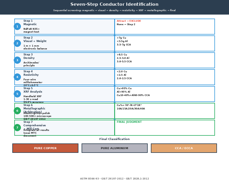
To improve identification accuracy and efficiency, establishing a systematic selection decision tree is essential. A recommended seven-step decision-making process is as follows:
Step 1: Magnetic Screening
Use a strong neodymium-iron-boron (NdFeB) magnet (grade N35 or higher). If the sample exhibits obvious magnetic attraction, it is excluded (ferromagnetic material); if no attraction occurs, proceed to Step 2.
Step 2: Visual Inspection and Weighing
Observe surface color and oxidation state, and weigh using an electronic balance. For a 1-m-long, 1-mm-diameter wire, a mass >7 g suggests copper; <3.5 g suggests aluminum; and 3.5–7 g suggests copper-clad aluminum (CCA).
Step 3: Density Measurement
Determine density via the Archimedes principle. A density >8.5 g/cm³ indicates copper; 2.5–3.0 g/cm³ indicates aluminum; and 3.0–5.5 g/cm³ indicates CCA.
Step 4: Resistivity Measurement
Measure electrical resistivity using the four-terminal (Kelvin) method. A resistivity <2.0 μΩ·cm indicates copper; >2.5 μΩ·cm indicates aluminum; and 2.0–2.5 μΩ·cm indicates CCA.
Step 5: XRF Analysis (if available)
Directly quantify elemental composition (e.g., Cu%, Al%, Fe%) via X-ray fluorescence (XRF) spectroscopy. Cu >95% indicates copper; Al >95% indicates aluminum; Cu 10–40% combined with Al 60–90% indicates CCA.
Step 6: Metallographic Analysis (for arbitration)
For cases requiring high-precision determination of the copper-cladding thickness ratio—or for dispute resolution—perform cross-sectional mounting, grinding, polishing, and microscopic measurement.
Step 7: Comprehensive Assessment and Material Certification
Integrate results from multiple methods to render a final judgment, and issue a material certificate (Mill Certificate / Material Test Certificate), documenting test data, test methods, test equipment, personnel, and date of testing.
Five Common Identification Pitfalls and Preventive Measures:
Pitfall 1: “Color-Only Judgment”
Oxidized copper turns black or green; aluminum wires electroplated with copper may appear identical to copper. Color alone is insufficient—quantitative methods such as density and resistivity measurements must be employed.
Pitfall 2: “Magnet-Only Judgment”
Both copper and aluminum are non-magnetic; magnetic screening serves only to exclude ferromagnetic contaminants and cannot differentiate between copper and aluminum.
Pitfall 3: “Weight-Only Judgment”
CCA contains an aluminum core, reducing its weight by 30–50% relative to pure copper—potentially causing misclassification as aluminum. Complementary methods (e.g., density measurement, copper-cladding ratio analysis) are required.
Pitfall 4: “Sole Reliance on Resistivity Measurement”
Resistivity measurements are susceptible to temperature fluctuations, cross-sectional area inaccuracies, and contact resistance errors. Cross-validation with density measurement and XRF analysis is mandatory.
Pitfall 5: “Uncontrolled Destructive Testing”
Metallographic and chemical analyses destroy the sample. Non-destructive tests (magnetic screening, visual inspection, density measurement, resistivity measurement, XRF) should always precede testing. Micro-destructive procedures (e.g., enamel coating removal) and fully destructive tests (metallography, chemical analysis) should be performed only when necessary.
Industry-Specific Application Differences:
- Transformers & Reactors: Aluminum wire is commonly used in low-voltage windings (especially in distribution transformers); copper wire is preferred for high-voltage windings due to lower losses.
- Motors: Small- and medium-sized motors predominantly use copper windings (for superior thermal management and starting performance); household appliance motors (e.g., air-conditioner compressors, washing-machine motors) employ both copper and aluminum.
- New Energy Vehicle (NEV) Traction Motors: Copper flat wire/hairpin conductors dominate, owing to their high power density.
- Wind-Powered Direct-Drive Generators: Copper windings prevail, aligned with trends toward larger-scale units.
- High-Frequency Inductors, 5G Base Stations, and Energy Storage Inductors: CCA is widely adopted for cost-effectiveness and lightweighting.
- Induction Heating Equipment, Resistance Welding Systems, and Low-Voltage Contactors: Aluminum wire may be selected where cost sensitivity is paramount.
- Recycling & Dismantling Enterprises: Must identify enameled wire composition (e.g., via density measurement and XRF) to enable accurate sorting and downstream processing.
By systematically mastering these identification methodologies, testing equipment, standards frameworks, and decision-making protocols, manufacturers and users can reliably distinguish among enameled copper wire, enameled aluminum wire, and copper-clad aluminum (CCA/ECCA) electromagnetic conductors—providing robust technical support across the entire electromagnetic wire value chain: design, procurement, production, quality control, and recycling.