


Magnet wire (also known as winding wire) is the core conductive material in electromagnetic equipment such as motors, transformers, and inductors. Any mistake in selecting magnet wire can lead to systemic failures such as overheating, insulation breakdown, vibration-induced wire breakage, efficiency degradation, or shortened lifespan. Therefore, upgrading from “procurement by drawing” to “selection by project” is a systematic approach that engineering teams must master.
This article, based on engineering practice, establishes a complete project-driven magnet wire selection framework around nine dimensions: project requirement identification, conductor selection, wire diameter and tolerance, enamel coating system, key performance, application scenarios, standards compliance, supplier evaluation, and decision-making processes.
Project Requirement Identification and Pre-Selection Preparation
Continuous operating temperature is the most critical single indicator, determining the thermal classification of the enamel coating; peak temperature (including short-term overload and welding process temperature) is usually required to be one level higher than the continuous operating temperature; humidity level determines whether a hydrolysis-resistant coating (such as AIW polyamide-imide) is needed; exposure to chemical media (such as transformer oil, refrigerant, electrolyte) requires the enamel coating to have chemical compatibility; mechanical stress conditions (vibration, shock, centrifugal force) require the enamel coating to have corresponding elongation and adhesion; at altitudes exceeding 3000 m, the current density needs to be adjusted accordingly due to the reduced heat dissipation caused by the drop in air pressure. # and Compliance Requirements: Different end markets correspond to different certification systems: UL 1446 is the general specification for electrical insulation systems in North America; EU CE and RoHS mandate compliance with the IEC 60317 series and hazardous substance restrictions; the PPAP documentation under the IATF 16949 system for automobiles requires suppliers to have corresponding quality management systems; and the AS9100 system for aerospace requires suppliers to have traceable batch management and material certificates of conformity (CoC).
The target market directly determines which standards are the “hard thresholds” that must be met. # Budget and Project Cycle: The proportion of cost to total material cost varies depending on the application: approximately 5-10% for household appliance motors, approximately 8-15% for industrial transformers, and approximately 12-20% for new energy vehicle drive motors.
Setting a target range for “cost per kW” or “budget per unit” at the initial project stage can quickly eliminate solutions that exceed the budget.
Simultaneously, a balance needs to be struck between small-batch customization and the economics of small rolls—the minimum order quantity (MOQ) for most projects is between 50–200 kg; demand below this range requires negotiation with suppliers to share inventory. Material Selection: Engineering Trade-offs of Copper, Aluminum, and Copper-Clad Aluminum The conductor material determines the conductivity, mechanical properties, and cost structure of the magnet wire.
Copper, aluminum, and copper-clad aluminum (CCA) are the three main conductor types, each with its own engineering boundaries. # Conductor: Performance Benchmark Copper (C11000 oxygen-free copper or C10100 electronic grade copper) is the performance benchmark for magnet wire, with an IACS conductivity of 100%, a density of 8.89 g/cm³, and a resistivity of 1.724 μΩ·cm at 20°C.
Copper magnet wire possesses optimal conductivity, best mechanical strength (soft tensile strength 220–260 MPa), and the highest fatigue life.
Aluminum (1350-O or 1370-O state) is a lightweight and low-cost option for magnetic wires, with an IACS conductivity of approximately 61%, a density of 2.70 g/cm³ (30% of copper), and a resistivity of 2.83 μΩ·cm.
Under the same resistance conditions, the cross-sectional area of an aluminum conductor is approximately 1.6 times that of copper, but its weight is only 48% of copper.
Conductor Material Selection: Engineering Trade-offs of Copper, Aluminum, and Copper-Clad Aluminum
This characteristic of “increased equivalent cross-section and halved weight” gives aluminum magnetic wire significant advantages in high-power, low-frequency, and lightweight applications such as large power transformers, wind turbines, solar inverters, railway traction transformers, and induction heating.
Termination of aluminum magnet wire typically employs cold pressing or ultrasonic welding rather than soldering, requiring dedicated termination solutions in the process design. # aluminum (CCA) conductors: a middle ground for cost-sensitive applications.
Copper-clad aluminum (CCA) uses a metallurgical cladding process to form a copper layer with a cross-sectional area ratio of 10–25% on the outside of an aluminum core.
Its conductivity is between that of pure aluminum and pure copper (approximately 67–85% IACS, depending on the copper layer ratio), and its density is approximately 3.63–4.06 g/cm³.
In high-frequency applications (>100 kHz), CCA exhibits superior high-frequency performance compared to pure aluminum due to the skin effect, allowing current to primarily flow through the copper layer.
CCA is primarily used in weight-sensitive mid-range applications where the mechanical strength of pure aluminum is insufficient—such as household appliance motors (e.g., air conditioner outdoor unit fan motors), small transformers, consumer electronics coils, and medium-power inductors.
It is important to note that CCA termination must use specialized processes (cold pressing, energy storage welding, or laser welding), and soldering is not recommended (as it will form a brittle Cu-Al intermetallic compound at the copper-aluminum interface). # Trade-offs Among Three Conductor Materials Conductor selection is essentially about finding a balance between five dimensions: conductivity, weight, mechanical strength, cost, and process compatibility.
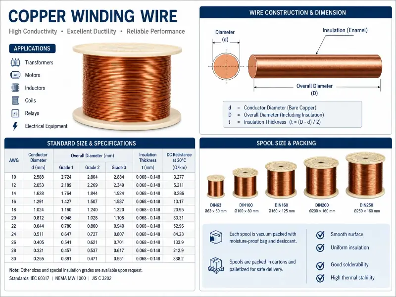
High power density, compactness, and high-frequency applications tend to favor copper; high power, lightweight, and low-frequency applications tend to favor aluminum; cost-sensitive, medium-performance, and special frequency scenarios may consider CCA. Gauge and Tolerance System Wire gauge selection is the geometric basis for magnet wire selection, determining multiple interconnected parameters such as slot fill factor, resistance, and enamel coating integrity test window. # between AWG and Metric Wire Gauges There are two main systems for wire gauge specifications: AWG (American Wire Gauge) is mainly used in the North American market, while metric diameters (mm) are commonly used in China, Europe, and Japan.
Wire Diameter and Tolerance System
Commonly used correspondences: AWG 14 ≈ 1.628 mm, AWG 18 ≈ 1.024 mm, AWG 24 ≈ 0.511 mm, AWG 30 ≈ 0.255 mm, AWG 36 ≈ 0.127 mm, AWG 40 ≈ 0.0799 mm, AWG 44 ≈ 0.0502 mm.
A unified wire gauge system must be maintained within the same project to avoid confusion in procurement and inventory caused by mixing different gauges. # between conductor diameter and outer diameter In engineering, “magnet wire diameter” has four different physical quantities: conductor diameter (bare copper/aluminum diameter, determines resistance), outer diameter (finished outer diameter, determines slot fill factor), outer diameter increment (outer diameter minus conductor diameter, determines insulation thickness), and out-of-roundness (the difference between the maximum and minimum diameters of the same cross-section, determines outer diameter uniformity).
Product specifications typically use a combination of “conductor diameter + enamel coating grade,” for example, “0.500 mm Grade 2” means a conductor diameter of 0.500 mm and enamel coating grade 2. # System and Compliance The IEC 60317 series standards specify permissible deviations and minimum enamel coating increments for each nominal diameter.
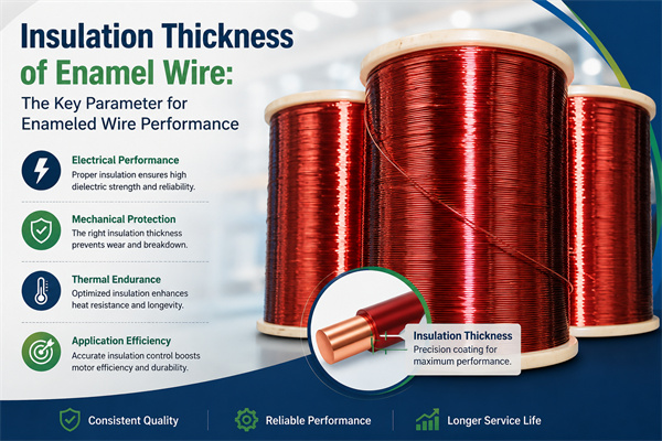
The minimum increments for Grade 1, Grade 2, and Grade 3 enamel coatings increase progressively, with Grade 3 being the thickest industrial-grade enamel coating (typically used in high-voltage transformers and new energy vehicle drive motors).
NEMA MW 1000-2020 uses a boundary constraint method of “minimum enamel coating increment + maximum outer diameter.” The two systems strictly correspond in technical specifications but differ in their expression. of Enamel Coating System and Thermal Class
Choosing an enamel coating system essentially involves a trade-off between thermal classification, mechanical strength, process compatibility, and chemical inertness.
The five mainstream enamel coating systems are: Polyurethane (UEW, Polyurethane) – offering the best direct solderability, allowing direct tinning in a 380°C solder bath without scraping; Thermal class – 130°C or 155°C (depending on the modified formulation); Moderate mechanical strength (elongation 25–35%); Primarily used in applications requiring direct soldering, such as small relays, coils, transformers, and sensors.
Polyester-imide (EIW) has a thermal class of 180°C and is the most commonly used enamel coating for F-class (155°C) motors; excellent mechanical strength (elongation 35–45%); better chemical resistance than PEW; good refrigerant resistance (suitable for air conditioning compressors); widely used in F-class motors, H-class transformers, and new energy vehicle drive motors.
Matching of Enamel Coating System and Thermal Class
Polyamide-imide (AIW) with a thermal class of 200°C is the standard enamel coating for Class H magnet wires; it has extremely high mechanical strength (elongation 40–50%) and excellent chemical resistance (resistant to refrigerants, transformer oils, and electrolytes); it is usually used as the outer layer of a double-coating system in conjunction with EIW or PEW to form a “composite coating” system; suitable for new energy drives, rail transportation, aerospace, and industrial motors in harsh environments.
Polyimide (PIW) with a thermal class of 220–240°C is the representative enamel coating for Class C; it has good mechanical strength (elongation 35–45%); it is radiation resistant and vacuum release resistant; however, it is more difficult to process (narrow coating window, high price); it is mainly used in aerospace, nuclear industry, military, and special motors. ### enamel coating grades and thermal classes | enamel coating grade | enamel coating increment | Applicable scenarios | |-|-|-| | Grade 1 | Minimum | Low voltage applications, large space margin | | Grade 2 | Medium | General industrial standard | | Grade 3 | Maximum | High voltage, high insulation strength | | thermal class | Temperature limit | enamel coating system | Typical applications | |-|-|-|-| | Y | 90°C | Oil-based enamel coating | Vintage equipment, low-cost scenarios | | A | 105°C | Oil-based modified | Low-end household appliances | | E | 120°C | Polyvinyl alcohol formaldehyde | Small transformers | | B | 130°C | Polyurethane | General purpose coils | | F | 155°C | polyester, polyesterimide | Class F motor, transformer | | H | 180°C | Polyamide-imide, polyesterimide | New energy drive, Class H motor | | C | 200°C+ | Polyimide, ceramic | Aerospace, special motor | ### enamel coating selection decision logic The selection of enamel coating follows a four-step method of “temperature baseline + process compatibility + special environment + cost”.
First, determine the thermal class baseline based on the continuous operating temperature.
| Enamel Coating Grade | Enamel Coating Increment | Applicable Scenarios |
|---|---|---|
| Grade 1 | Minimum | Low-voltage applications, large space margin |
| Grade 2 | Medium | General industrial standard |
| Grade 3 | Maximum | High voltage, high insulation strength |
Then, determine whether direct solderability (UEW/AIW) is required based on the termination process.
The third step is to check the special environment (oil resistance, refrigerant resistance, chemical resistance).
| Thermal Class | Temperature Limit | Enamel Coating System | Typical Applications |
|---|---|---|---|
| Y | 90°C | Oil-based enamel | Legacy equipment, low-cost scenarios |
| A | 105°C | Oil-modified | Low-end home appliances |
| E | 120°C | Polyvinyl formal | Small transformers |
| B | 130°C | Polyurethane | General coils |
| F | 155°C | Polyester, polyester-imide | F-class motors, transformers |
| H | 180°C | Polyamide-imide, polyester-imide | New energy drives, H-class motors |
| C | 200°C+ | Polyimide, ceramic | Aerospace, special motors |
Finally, select the enamel coating system with the lowest cost among the solutions that meet the first three criteria. electrical and mechanical performance indicators The enamel coating level and thermal class are macro-constraints.
The nominal value and tolerance of the resistance per kilometer are specified by IEC 60317 / NEMA MW 1000.
Class A tolerances are typically ±2%, while the more stringent Class B tolerances are ±1%.
Key Electrical and Mechanical Performance Indicators
DCR sampling should be performed on the windings before they leave the factory; deviations exceeding the standard indicate abnormalities in the conductor cross-section or material. # Voltage (BDV) Breakdown voltage is a core indicator of the insulation strength of an enamel coating.
It is measured by applying an increasing voltage across the enamel coating until breakdown occurs.
The minimum BDV for Grade 2 enamel coatings depends on the conductor diameter—typical BDV ≥ 600 V for 0.100 mm conductors, ≥ 2000 V for 0.500 mm conductors, and ≥ 3000 V for 1.000 mm conductors.
The 800V platform for new energy vehicles requires a much higher BDV (BDV) for the magnetic wire than the traditional 400V platform. ### enamel coating continuity (pinhole test): enamel coating continuity is tested through an aqueous solution pinhole test or a saline solution pinhole test, measured in “permissible pinholes per 30 m”.
Grade 2 enamel coatings typically require ≤ 5 pinholes per 30 m, while Grade 3 has even stricter requirements.
Pinholes are the “weak points” of the enamel coating, the starting point for partial discharge and early breakdown, and are particularly critical for high-frequency and high-voltage applications. # and adhesion: The enamel coating must be able to withstand bending and stretching during winding, embedding, and shaping processes without cracking or peeling.
IEC 60851-3 specifies the minimum bending diameter required for the enamel coating to not crack after winding.
Grade 2 enamel coatings typically require a diameter equal to 1 times the conductor diameter (i.e., the diameter of the conductor itself) without cracking. # Temperature The cut-through temperature is the critical temperature at which the enamel coating fails mechanically at high temperatures.
Project Application Scenarios and Magnet Wire Mapping
It is the temperature at which the enamel coating softens and adheres under increased temperature and pressure, leading to a short circuit between two intersecting enameled wires.
Class H magnetic wires require a cut-through temperature ≥ 320°C. # and Chemical Resistance Magnetic wires used in air conditioning compressors and refrigeration systems must pass a refrigerant resistance test (IEC 60851-15).
The enamel coating should not crack, blister, or delaminate after immersion in refrigerants such as R22, R410A, and R134a.
| Application Scenario | Core Requirements | Conductor Selection | Enamel Coating | Typical Wire Diameter | Additional Requirements |
|---|---|---|---|---|---|
| Transformer | Voltage resistance, oil resistance, stability | Copper (critical) / Aluminum (large distribution) | EIW, PEW, dual-coat | AWG 14–24 (0.5–1.6 mm) | Transformer oil resistance, impregnation process compatibility |
| Motor (industrial/home appliance) | Slot fill, heat dissipation, mechanical strength | Copper/Aluminum/CCA | EIW, dual-coat (PEW+AIW) | Slot fill and current density calculation | Centrifugal force resistance, AIW for high-speed motors |
| Inductor/High-frequency coil | Q value, frequency characteristics | Copper (Litz wire) | PEW, EIW | Litz multi-strand fine wire | Skin effect suppression (>20 kHz) |
| Home appliance & consumer electronics | Cost, mass production stability, certification | Copper (precision) / CCA (mid-low) | PEW, UEW | AWG 24–32 | CCC, UL, VDE certification |
| New energy vehicle | High voltage resistance, high power density, high reliability | Copper (drive) / Aluminum (partial) | H-class and above AIW, dual-coat | AWG 14–22 | IATF 16949 + PPAP, 800V platform Grade 3 |
| Rail transit/aerospace | Extreme environment, long life, high reliability | Copper (high-purity oxygen-free) | PIW, AIW, special composite | Strict design margin matching | EN 45545-2 HL3, AS9100, MIL-W-583 |
Magnetic wire used in transformer impregnation processes requires resistance to transformer oil (mineral oil) or ester oil, while magnetic wire used in electroplating workshops and electrolysis industries requires resistance to acids and alkalis. # Loss Factor (tan δ) The dielectric loss factor (tan δ) is a key indicator for high-frequency applications.
The lower the tan δ, the smaller the insulation dielectric loss at high frequencies, and the higher the Q value of the coil.
PIW has a tan δ of approximately 0.003 at 1 kHz, UEW approximately 0.008, and PEW approximately 0.010. # Wire Self-bonding magnetic wire involves applying a layer of hot melt adhesive (such as polyamide alcohol or butyral) over a conventional enamel coating.
When heated to 110–180°C, the hot melt adhesive melts, solidifying the coil.
This is a key solution for winding frameless coils. Application Scenarios and magnet wire Mapping Different application scenarios have vastly different requirements for magnet wire.
Standards Compliance and Certification System
Selection engineers need to establish a clear mapping relationship between project categories and magnet wire types.
Conductors are typically copper (critical transformers) or aluminum (large power distribution transformers); enamel coatings include EIW, PEW, or double-coated EIW + AIW; wire diameter is usually thicker (AWG 14–24 / 0.5–1.6 mm) for easier winding; additional requirements include transformer oil resistance, compatibility with impregnation processes, and high enamel coating integrity. # Project Specific Analysis The core requirements for magnet wire in motors (industrial motors, servo motors, household appliance motors, EV drive motors) are slot fill factor, heat dissipation, mechanical strength, and thermal classification.
Conductors are selected from copper, aluminum, and CCA based on power density and weight requirements; enamel coatings are typically EIW or double-coated (PEW + AIW); wire diameter is calculated based on slot fill factor and current density; high-speed motors also require consideration of enamel coating resistance to centrifugal force, and AIW is the standard choice for high-speed motor enamel coatings. # Energy Vehicle Special Analysis The requirements for magnetic wire in new energy vehicles (drive motor, OBC, DC-DC converter, motor controller) are high withstand voltage, high power density, and high reliability.
The conductor is copper (mainstream for drive motors) or aluminum (some models); the enamel coating must be H-grade or higher (AIW, double-coated EIW + AIW); the wire diameter is relatively thick (AWG 14–22); BDV requirements are significantly higher than for industrial motors; it needs to meet the PPAP requirements and traceability under the IATF 16949 system. # Transit and Aerospace Special Analysis The requirements for magnetic wire in rail transit (traction motor, traction transformer, pantograph) and aerospace (aviation motor, airborne transformer) are extreme environment adaptability, high reliability, and long lifespan.
The conductor is made of copper (high-purity oxygen-free copper); the enamel coating is PIW, AIW, or a special composite coating; the wire diameter is strictly matched to the design margin; it must meet specific standards such as EN 45545-2 HL3 (railway fire protection), AS9100 (aerospace), and MIL-W-583 (military winding wire). Compliance and Certification System Standards are a “hard threshold” for supplier qualifications and product quality; different target markets correspond to different standard systems.
For example, IEC 60317-0-1 is a general requirement; IEC 60317-13 is for self-adhesive enameled round copper wire; IEC 60317-21 is for polyamide-imide enameled round copper wire; IEC 60317-47 is for polyurethane enameled round copper wire; and IEC 60317-67 is for polyester-imide enameled round copper wire.
Each sub-standard has a strict correspondence with Annex C of NEMA MW 1000, and mutual recognition of standards can be achieved through table lookup. # US standard system NEMA MW 1000-2020 is a master document published by the National Electrical Manufacturers Association (NEMA) for magnetic wire, which uniformly numbers all magnetic wire specifications using “MW + number” (e.g., MW 35-C polyester enameled copper round wire, MW 80-C polyamide-imide enameled copper round wire).
NEMA MW 1000 also specifies that “adding the letter C” indicates compliance with environmental requirements such as RoHS. # and Chinese standards JIS C 3202 is a Japanese industrial standard, corresponding to IEC 60317, but with localized adjustments for wire diameter specifications.
Supplier Evaluation and Quality Control
The GB/T 6109 series is a Chinese national standard, equivalent to IEC 60317, and is the most frequently cited standard by domestic magnetic wire suppliers. # Application Standards UL 1446 is the general specification for electrical insulation systems in North America, defining the test methods for magnet wire in insulation systems; ASTM B-566 is a specific standard for copper-clad aluminum wire; EN 45545-2 is a fire protection standard for rail transportation; AS9100 is a quality system standard for aerospace; IATF 16949 is a quality system standard for automobiles. # Selection Strategy When selecting standards for projects, we follow the three elements of “target market + application scenario + customer requirements”.
For projects exported to North America, we prioritize NEMA MW 1000; for projects exported to the EU, we prioritize IEC 60317; for domestic projects, we prioritize GB/T 6109; for automotive projects, we combine IATF 16949 + PPAP; for aerospace, we combine AS9100 + MIL-W; for rail transportation, we combine EN 45545-2 + fire protection rating report. Evaluation and Quality Control The supplier’s capabilities directly determine the reliability of the project’s supply chain.
B2B selection must be systematically evaluated from four dimensions: process, quality, capacity, and business. # Capability Evaluation Process capability determines whether the supplier can stably produce the required materials for the project.
The structure of the coating furnace (vertical furnace, muffle furnace, catalytic hot air furnace) affects the uniformity of the coating; the coating thickness control system (online laser diameter measurement + closed-loop feedback) determines the tolerance control accuracy; the conductor drawing process (sliding type, sliding + storage type) affects the surface quality and consistency of the conductor; the cladding process (copper-clad aluminum cladding welding, continuous extrusion, hydrostatic extrusion) determines the interfacial bonding strength of CCA.
Suppliers need to demonstrate videos, photos, or provide on-site visits for key processes. # Management System Suppliers must be certified to the ISO 9001 basic system.
Each project batch requires a Certificate of Materials (CoC) and a Certificate of Accreditation (CoA).
Critical projects also require a First Article Inspection Report (FAIR) and Production Part Approval Procedure (PPAP) documents. # and Delivery Capacity Supplier capacity must match the batch size requirements of the project.
Household appliance projects have an annual usage of 50–500 tons, requiring suppliers to have multiple production lines; new energy vehicle (drive motor) projects have an annual usage of 200–2000 tons, requiring suppliers to have large-scale production capacity and rapid expansion capabilities; aerospace and military projects have an annual usage of 5–50 tons, but have extremely high requirements for batch consistency and complete documentation.
Project-Driven Selection Decision Process
| Step | Process Content |
|---|---|
| Step 1: Project Requirements | List electrical parameters, environmental conditions, certification requirements, cost budget, project cycle |
| Step 2: Candidate Screening | Screen 3-5 candidate magnet wire specifications per IEC 60317 / NEMA MW 1000 |
| Step 3: Parameter Comparison | Compare DCR, BDV, enamel continuity, thermal class, process compatibility, cost |
| Step 4: Sample Verification | Request 50-500 m samples, perform winding, embedding, impregnation, temperature rise, life tests |
| Step 5: Finalization & Stocking | Sign technical agreement, place first order, reserve safety stock |
Supplier lead times (typically 4–8 weeks), minimum order quantities (typically 50–200 kg), and inventory strategies are also key evaluation points. # and Sustainability
In terms of sustainability, European customers require suppliers to provide carbon footprint reports (ISO 14067), Conflict Minerals Declaration (CMRT), and REACH and RoHS compliance declarations; ESG ratings have become an implicit threshold for major customer access. # Acceptance and Warehousing Inspection Sampling acceptance must be performed upon arrival of goods.
The sampling ratio is based on GB/T 2828.1 (equivalent to MIL-STD-105E), general inspection level II, AQL 0.65.
The handling procedure for non-conforming batches must be agreed upon in writing with the supplier beforehand. project-driven selection decision-making process transforms the above 9 dimensions into an executable 5-step decision-making process, which is key to the implementation of engineering methodologies. # 1: Project Requirements List List electrical parameters (voltage/current/frequency), environmental conditions (temperature/humidity/chemical media/vibration), certification requirements (UL/CE/CCC/IATF 16949/AS9100), cost budget (cost per kW / budget per unit), and project cycle (2 weeks for initial sample / 8 weeks for mass production). # 2: Candidate Magnetic Wire Scheme Screening Based on the requirements list, screen 3–5 candidate magnetic wire specifications from the IEC 60317 / NEMA MW 1000 standards, including conductor material, wire diameter, enamel coating system, and thermal class. # 3: Engineering Parameter Comparison Compare the conductor resistance, breakdown voltage, enamel coating continuity, thermal class, process compatibility, and cost of candidate solutions item by item, creating a comparison table. # 4: Sample Verification and Lifetime Testing Obtain samples (typically 50–500 m) from candidate suppliers and perform project-specific verification tests (winding test, wire embedding test, immersion test, temperature rise test, lifetime test).
New energy vehicle drive motor projects also require 1000 hours of high-temperature durability testing and 500 cycles of thermal cycling testing. # 5: Solution Finalization and Material Preparation Based on the sample verification results and commercial terms, determine the final solution, sign a technical agreement (including specifications, tolerances, test methods, acceptance criteria, and non-conformance handling procedures), place the first order, and reserve safety stock. Magnet Wire Application Selection Recommendations Discuss selection priorities according to project category.
For motor projects, priority should be given to the matching of conductor materials and enamel coating temperature resistance—high power density motors should use copper conductors + H-class enamel coating (AIW or double coating), high-power low-frequency motors can consider aluminum conductors + EIW or PEW enamel coating, and new energy drive motors must have voltage resistance (800 V platform Grade 3) and automotive-grade quality system (IATF 16949 + PPAP); for transformer projects, the focus should be on the compatibility of enamel coating voltage resistance and impregnation process—dry transformers can choose PEW or EIW, oil-immersed transformers must ensure that the enamel coating is oil-resistant (mineral oil or ester oil), and high-voltage transformers (35 kV and above) require Grade 3 enamel coating or wrapped insulation reinforcement; for inductors and high-frequency applications, the focus should be on Q value and skin effect—low frequency (<20 For applications with a frequency of kHz, ordinary round copper wire is used.
For high-frequency applications (>20 kHz), Litz wire structure (multi-strand fine wire twisted together) must be used.