

In the field of enameled wire, “high strength” encompasses three independent technical dimensions: the tensile strength of the conductor itself, the mechanical strength of the enamel coating, and the ability of the winding to resist inter-turn short circuits. These three differ significantly in their implementation paths, costs, and failure modes. In engineering practice, failure to clearly distinguish between them can lead to selection errors that directly result in winding breakage, enamel coating cracking, and winding failure.
Another easily overlooked physical constraint is that while hard-drawn conductors can increase tensile strength to 455–460 MPa, elongation decreases simultaneously to 1.0%–1.5%. Within this range, the matrix almost completely loses its ductility buffering capacity, and the bending strain during winding is entirely borne by the enamel coating. The enamel coating thus transforms from a passive protective layer to the sole stress-absorbing layer. This shift in mechanical mechanism forms the core of this paper’s discussion.
The data cited in this article are partly derived from publicly available ASTM and IEC standard clauses, and partly from manufacturing inspection records and field application verification results.
Hard-Drawn Conductor Properties
How Cold Working Reshapes Copper Conductor Properties
Copper conductors are high-precision manufactured products, requiring wire drawing and one or more cold working processes. Cold working alters the material’s mechanical response through grain deformation and density increase, resulting in a bidirectional change of increased strength and decreased ductility.
This process is crucial. Pure copper is a low-strength, high-ductility soft-drawn material, and annealed conductors are used in the vast majority of enameled wire manufacturing. The hard-drawn temper, by contrast, is produced to order for specific application requirements.
Temper Designations: O60, H02, H04, H08
In the ASTM B1 and NEMA MW 1000 systems, the processing conditions of copper conductor have a standard designation system:
- O60 (Soft / Annealed)—Fully soft-drawn, offering maximum ductility and flexibility. Tensile strength: 210–255 MPa, elongation: 15–35%, conductivity: 101% IACS. This is the most widely used temper and the most forgiving in winding.
- H02 (½ Hard)—A compromise between strength and flexibility, suited to applications that require some mechanical protection without excessive loss of winding flexibility.
- H04 / H08 (Hard Drawn) — Hard-drawn state. Tensile strength 345–455 MPa, elongation decreases to 1.5%–2.5%, conductivity approximately 97% IACS.
The difference between H04 and H08 should be noted: H08 has a higher degree of work hardening, resulting in greater strength but lower ductility. The cost of this strength gain depends on the wire diameter, specifications, and specific grade.
Conductor Material: C11000 as the Industry Baseline
The conductors of hard-drawn winding wires are mostly made of C11000 (ETP electrolytic copper), with a copper content > 99.90% and 0.02%–0.04% Cu₂O residue. This grade is the industry-recognized standard for electrical conductors, with a resistance of 0.017241 Ω·mm²/m.
- C10100 / C10200 (Oxygen-Free Copper)—Copper content > 99.95% / > 99.99%, almost oxygen-free. Used in high-frequency and ultra-high vacuum applications because oxygen forms oxide interfaces at high temperatures, increasing losses.
- C13500 (Copper-Silver Reinforced) — Contains 0.75%–1.25% silver, with an annealed strength of 220–280 MPa and minimal conductivity degradation.
Under hard-drawn conditions, the main source of strength improvement is work hardening, rather than alloy strengthening. The advantages of the silver-strengthened approach are correspondingly diminished in the hard-drawn state, as work hardening already accounts for a large portion of the strength margin.
Thermal Expansion Mismatch Stress
Copper has a coefficient of thermal expansion of 17.0 × 10⁻⁶ /°C and a melting point of 1083°C. When hard-drawn enameled wire operates at high temperatures for extended periods, the substrate expands while the adhesion strength of the enamel coating remains constant, resulting in accumulated shear stress between the two. Therefore, the thermal shock resistance requirements for enamel coatings in hard-drawn enameled wire are significantly higher than those in soft-drawn wire.
Trade-Offs Between Strength, Ductility, and Conductivity
Comparison of the Three Tempers
| Temper | Tensile Strength | Elongation | Conductivity | Resistivity (Ω·mm²/m) | Typical Applications |
|---|---|---|---|---|---|
| O60 annealed | 210–255 MPa | 15–35% | 101% IACS | 0.017241 | Conventional motors and transformer windings |
| H02 half-hard | approx. 280–320 MPa | 8–12% | approx. 99% IACS | approx. 0.0175 | Windings requiring moderate mechanical strength |
| H04 hard-drawn | 345–420 MPa | 1.5–2.5% | approx. 97% IACS | 0.01777 | Traction motors, special windings, high-tension applications |
These figures must be read together. Tensile strength rises from 255 MPa to 420 MPa, an increase of 65%; elongation falls from 15% to 1.5%, a reduction of 90%; conductivity drops by 4 percentage points.
Tensile strength and elongation are two sides of a single trade-off, not independent parameters. Specifying tensile strength implies accepting a corresponding elongation level.
Effect of Wire Diameter on Hard-Drawn Parameter Spread
When the same H08 state is applied to different wire diameters, the parameter dispersion is significant:
| Nominal Diameter | Elongation | Tensile Strength |
|---|---|---|
| 7.348 mm | 2.2% | 385 MPa |
| 5.189 mm | 1.7% | 415 MPa |
| 3.264 mm | 1.3% | 440 MPa |
| 2.588 mm | 1.2% | 445 MPa |
| 1.628 mm | 1.0% | 455 MPa |
| 1.024 mm | 1.0% | 460 MPa |
When a thin wire reaches 460 MPa tensile strength, its elongation is only 1.0%, meaning the buffer margin is almost zero. At fine diameters, hard-drawn wire therefore depends far more heavily on the mechanical performance of its coating.
Scope of ASTM B1
The scope of ASTM B1-13 (2018) is clearly defined as: covering electrical hard-drawn round copper wire, testing tensile strength, elongation and resistance, and stipulating that finished wires must not have joints (joints on the front rod of the wire drawing must comply with best commercial practice).
The tensile properties table in the standard gives the limits according to the nominal diameter, with typical values as follows:
- Nominal diameter 11.684 mm → 49,000 psi (340 MPa), elongation 3.8%
- Nominal diameter 10.464 mm → 51,000 psi (350 MPa), elongation 3.3%
- Nominal diameter 9.266 mm → 52,800 psi (365 MPa), elongation 2.8%
The rule is clear: as the diameter increases, the requirements for elongation are relaxed, and as the diameter decreases, the strength requirements are increased.
Sampling and Acceptance Rules Under ASTM B1 and ASTM B8
Division of Scope Between the Two Standards
- ASTM B1—Specification for bare hard-drawn round copper wire: dimensional tolerances, tensile strength, elongation, and resistance.
- ASTM B8—Specification for magnet wire (enameled wire), which references B1 for the mechanical properties of the conductor portion while adding requirements for the coating itself.
In actual procurement, both standards are applied in combination: the B8 standard for enameled wire as a whole, and the B1 standard for copper conductor.
Key Tensile Test Parameters
According to the ASTM B1/B8 system, tensile tests must strictly adhere to the following parameters:
- Gauge length 10 in (250 mm)—not 50 mm. The distinction changes the reported elongation value, so the gauge length must be stated whenever figures are compared.
- Crosshead speed ≤ 3 in/min (75 mm/min)—An excessive loading rate drives the reported elongation below its true value.
- Retest rule—If the initial test fails, two additional specimens are taken and the result is judged on the average of all three.
Springback after winding is the second parameter governed by the same pairing. Because the hard-drawn temper retains only 1.0%–1.5% elongation, the conductor stores elastic strain rather than accommodating it plastically, and the residual recovery force at the coil end places additional load on the coating. For this reason the springback angle is measured under IEC 60851-3, and a rising springback value at constant diameter indicates that the temper has moved further into the hard-drawn range than the purchase specification intends.
The retest rule carries practical weight. Hard-drawn wire is a material with a pronounced brittleness tendency, and the probability of a spurious failure on a single specimen is not negligible, particularly where clamping has damaged the sample. Judging on a single specimen alone will reject conforming lots.
How Sampling Location Affects Data Validity
Several details during the verification process can compromise the validity of the data:
- Localized crushing at the ends can cause fracture before the gauge length has been fully strained. The fracture point must fall inside the effective gauge length; if it does not, the specimen is reported separately.
- Post-fracture measurement is taken with the halves rejoined; clamp displacement must not be counted toward elongation.
- The cross-sectional area used in the calculation must come from the actual dimensions of the specimen, not from nominal values.
- Elevated strength with depressed elongation may serve as an indicator for investigating processing conditions, but it is not sufficient on its own to establish that a given wire-drawing operation is out of control.
- Resistivity must be measured on the as-delivered cross-section of the test specimen; the specimen must not be stretched to a regular shape before measurement.
Standard sampling practice takes specimens from several positions within the same spool and retains each specimen’s own diameter measurement and mechanical designation, rather than combining them into a single average. Pooling the results masks lot-to-lot variation in manufacturing condition.
Material State Versus Finished-Wire Performance
The standards specify material state, not finished-wire performance. High tensile strength is not equivalent to high winding short-circuit strength: coating performance, winding geometry, and varnish impregnation all intervene between the two. Treating conductor tensile strength as a direct proxy for winding or mechanical strength is not technically sound.
How Hard-Drawn Conductors Load the Enamel Coating
The Coating Shifts from Protection to Load Bearing
The elongation of soft-drawn copper is 15%–35%. During the winding process, the copper substrate deforms first, absorbing most of the bending strain. The enamel coating only needs to deform accordingly, resulting in a relatively minor load.
In the hard-drawn state, elongation accounts for only 1.0%–2.5%, the matrix hardly participates in ductility deformation, and all bending strain is borne by the enamel coating. The functional properties of the enamel coating are thus fundamentally transformed:
- Shifted from a passive protective layer to a load-bearing layer
- Shifted from resisting abrasion to withstanding repeated bending strain.
- Shifted from a cosmetic defect to the exposure of bare conductor.
The characteristic failure sequence is as follows: where winding tension has not been reset for hard-drawn wire, fine cracks form in the coating at the payoff eye, and the bare copper underneath is not discovered until the entire spool has been wound.
Three Characteristic Failure Modes
Scratch-induced failure—Mechanical abrasion thins the coating locally until it wears through. This is the most frequent failure mode; the countermeasures are an AIW coating system together with correct payoff eye and tension settings.
Cracking failure—The coating cracks under bending strain. The countermeasures are coating adhesion and flexibility; composite coatings such as EIW/AIW perform markedly better here than single-layer thin coatings.
Thermal shock failure—The copper substrate expands while the coating adhesion remains unchanged, generating shear stress at the interface. The countermeasures are the coating’s thermal shock rating and the design of the winding operating temperature.
Under IEC 60317-71:2020 and comparable standards, the criteria for the flexibility and adhesion tests are no cracking and sound adhesion after winding. For fiberglass-covered wire the adhesion test is specified more precisely: at 10% strain, neither the fiber serving nor the coating shall exhibit any loss of adhesion.
Residual Stress at the Coating Interface
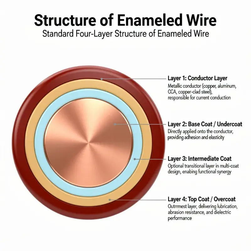
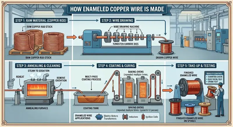
The hard-drawn copper conductor inherently carries cold working residual stress. This stress exists before the coating process, and is partially released during the high-temperature processes of coating and curing (typically 350–450°C for the base coat and 400–500°C for the top coat), with the remainder constrained by the enamel coating in the area adjacent to the interface.
The engineering consequence is that coating adhesion on hard-drawn enameled wire is more sensitive than on soft-drawn wire, and more dependent on surface cleanliness and preheating practice before coating. Residual drawing lubricant, oxide film, and plating pre-treatment quality all bear directly on the final adhesion result.
Matching Enamel Coating Systems to the Hard-Drawn Temper
Principal Properties of the Five Coating Systems
Classified according to IEC 60317 series and NEMA MW 1000-2018:
- Polyurethane (PU / UEW)—130°C. Good solderability, high elasticity, and strong recovery.
- Polyester (PEW / QZ)—155°C. The cost-effective mainstream system.
- Polyester-imide (EIW / QZXY)—180°C. Balanced mechanical performance.
- Polyamide-imide (AIW / QZY)—200/220°C. Outstanding thermal shock resistance.
- Polyimide (PI)—220/240°C. Best chemical resistance.
The corresponding NEMA designations are approximately: MW 15 / MW 18 (round wire / flat wire, polyvinyl formal), MW 79–83 (polyurethane series), MW 30 / MW 102 (polyester-imide), MW 45 / MW 46 (polyester glass fiber).
Coating Suitability Matrix for Hard-Drawn Temper
| Coating System | Thermal Class | Abrasion Resistance | Bending Strain Capacity | Hard-Drawn Suitability | Typical Applications |
|---|---|---|---|---|---|
| PU / UEW | 130°C | Poor | Good | Not recommended | Low-tension, solderable windings |
| PEW / QZ | 155°C | Moderate | Moderate | Conditional | General hard-drawn windings |
| EIW / QZXY | 180°C | Good | Good | Recommended | Traction motors and special windings |
| AIW / QZY | 200–220°C | Excellent | Excellent | Strongly recommended | High-tension, high-thermal-class applications |
| PI | 220–240°C | Excellent | Excellent | Recommended | Extreme temperature and high-frequency applications |
PU is excluded in the hard-drawn temper on grounds of hardness rather than thermal capability. During winding, both payoff eye friction and de-reeling tension act on the coating surface; a soft coating lacks the abrasion resistance to absorb these loads, breaks down first, and exposes the conductor.
Why AIW Is Preferred for Hard-Drawn Wire
The softening breakdown temperature of polyamide-imide typically exceeds 330–350°C, far above its nominal 200°C/220°C thermal class. Under thermal shock exceeding 200°C, internal stress in the coating remains low and the coating does not crack.
Inspection data point to the same conclusion: AIW achieves markedly higher abrasion resistance and tensile adhesion than standard polyester and polyester-imide. These two properties are precisely what the hard-drawn temper demands.
For solid conductors, the coating system corresponds to EI/AIW (QZY). Where greater mechanical protection is required, a fiberglass-covered construction is available, but the thermal shock rating and breakdown voltage must then be re-qualified against it.
Winding Process and Equipment Parameters
Recalibrating De-Reeling Tension
NEMA MW 1000-2018 devotes a dedicated clause to de-reeling (winding) tension. The de-reeling tension characteristic of hard-drawn wire is inherently higher than that of soft-drawn wire. Where winding equipment retains the tension settings used for soft-drawn wire, the coating is inevitably subjected to stresses beyond its design limits.
The recommended changeover procedure is: run an unloaded winding and inspect the coating surface for whitening, indentation, or fine cracking, then raise speed and tension progressively. A practical shop-floor indicator is that if a fine burr can be felt under the fingernail on the coated surface during winding, the tension setting is too high.
Winding Speed, Guides, and Dies
In addition to tension, the following variables also need to be controlled:
- Winding speed—Higher speed produces greater dynamic tension and a correspondingly heavier impact load on the coating. Hard-drawn wire in particular requires margin for speed reduction.
- Payoff eye and dies—Contact surfaces must be smooth and burr-free. Hard-drawn wire has high surface hardness, so any discontinuity raises the likelihood of coating damage.
- Spool tension—Tension fluctuation at the guide rollers and take-up shaft is transmitted directly to the winding point.
Narrowing of the Coating Process Window
Coating of hard-drawn wire carries a specific requirement: the conductor surface must be clean before coating. Residual drawing oil and oxide film directly impair adhesion, and adhesion on the hard-drawn temper is in turn more sensitive to interface condition, because the partial release of residual stress during curing disturbs that interface.
Within the curing window of 350–450°C for the base coat and 400–500°C for the top coat, coating thickness must be held to ±2.5 μm and monitored in-line with a laser thickness gauge. A coating that is too thin lacks the required strength; one that is too thick is more prone to cracking along the substrate under the high stresses characteristic of the hard-drawn temper.
Drafting the Purchase Specification
Specify Mechanical Properties as Pairs
The central requirement in drafting a specification is this: a label of “high strength” or “hard-drawn” is not a specification. Tensile strength and elongation must be stated as a pair.
A conformant notation, structured per IEC 60317-27 (representation of enamelled copper wire), is as follows:
14.00 × 1.00 + 0.20
Rp0.2 = 150 MPa (min)
A5 = 1.5% (min)- The first line gives the conductor dimensions and the finished dimensions.
- The second line gives the minimum proof strength (Rp0.2).
- The third line gives the minimum elongation (A5, 250 mm gauge length).
Specifying tensile strength without elongation is the most common defect in a purchase specification. Across different coating suppliers and manufacturing sources, elongation under the same nominal “hard-drawn” designation may differ by more than a factor of two. Unless stated explicitly, the ductility actually delivered will not match what was intended.
Applicable Standards
| Standard | Scope | Relevance to This Topic |
|---|---|---|
| IEC 60317-0-1:2013 | General requirements for enameled round winding wire | Round wire nominal 0.020–2.500 mm; resistance per Annex B/C |
| IEC 60851-3 | Mechanical and electrical performance tests | Elongation, springback, flexibility, and adhesion |
| ASTM B1 | Hard-drawn round copper wire | Dimensions, tensile strength, elongation, and resistivity |
| ASTM B8 | Magnet wire | References B1 for conductor mechanical properties |
| ASTM B246 | Tin-coated hard-drawn and mid-hard-drawn copper wire | Corresponding requirements for tin-coated wire |
| NEMA MW 1000-2018 | Magnet wire | Thermal class, coating systems, de-reeling tension |
| GB/T 6109 series | Enameled round winding wire | Corresponding requirements in the Chinese national system |
| EN 13602 | Drawn round copper wire of copper and copper alloys | European counterpart system |
One qualification must be noted: the default conductor condition in the IEC 60317 volumes and the GB/T 6109 series is soft-drawn or half-hard-drawn. Hard-drawn enameled wire falls under custom and special-order supply within both systems. The temper designation and the mechanical requirements must therefore be stated separately in the purchase specification; they cannot be satisfied by reference to the general volumes alone.
Additional Specification Items
In addition to mechanical properties, the specifications should also clearly state:
- Conductor grade (C11000 / C10200 / C13500)
- Temper designation (H04 / H08, or as described in ASTM B1)
- Coating system and thermal class (PEW 155 / EIW 180 / AIW 200-220)
- Coating thickness grade (Grade 1 / 2 / 3)
- Breakdown voltage requirement
- Maximum coating thickness, single side or both sides
- Packaging form (spool, coil, 30–150 kg wood-plastic composite reels)
Five-Step Selection Framework
Selection proceeds along the following path.
Establish the application constraints. Operating temperature, winding tension, shock, vibration, and repeated flexing conditions must all be defined. Thermal class and mechanical strength requirements follow from these constraints rather than the reverse.
Select the conductor temper. Choose among O60, H02, and H04/H08, converting the general requirement of “high strength” into a defined range of tensile strength and elongation. Where elongation of 8% or more is acceptable, H02 will generally suffice and H08 is unnecessary.
Select the coating system. For the hard-drawn temper the default is EIW/AIW. Where a higher thermal class is required, AIW/QZY 200–220 applies. PU can be excluded from consideration in the hard-drawn case.
Verify the process window. Confirm that the tension, speed, and payoff eye settings of the winding equipment suit the wire, and that the pre-coating treatment and curing profile are compatible. Until this is confirmed, the conclusions of the preceding three steps are not executable.
Issue the specification and verify on receipt. State tensile strength and elongation as a pair, with sampling and retest provisions attached. On receipt, sample and inspect to ASTM B1/B8, for which measured elongation remains the one verification item that cannot be substituted.
Typical Applications
Traction motors and new energy vehicle drive motors—High rotational speed, high torque, and vibration produce significant mechanical stress in the winding. A hard-drawn conductor with AIW coating is the common configuration, with emphasis on coating abrasion resistance and long-term thermal cycling endurance.
Converter and traction transformers—The winding must withstand alternating electromagnetic forces and therefore requires high mechanical stability. Hard-drawn wire is used in conjunction with VPI impregnation, and the integrity of the coating before impregnation directly determines the quality of the impregnated system.
Industrial generators and special windings—Large conductor cross-sections combined with high mechanical tension make the tensile advantage of the hard-drawn temper significant. Because the conductors are of relatively large diameter here, the loss in elongation remains within manageable limits.
High-tension winding and formed coils—The conductor must retain its shape through the forming process, where de-reeling tension and coating adhesion form the primary tension point.
Conclusion
High strength is an outcome, not an objective. The 455–460 MPa tensile strength obtained in the hard-drawn temper carries a cost: elongation of 1.0%, conductivity of 97% IACS, and a coating system and winding process that must both be redesigned.
The technically meaningful specification is the paired one: tensile strength and elongation agreed together. Once both are fixed, the conductor temper, coating system, de-reeling tension, and equipment requirements all follow by derivation. Where this pair is left undefined, subsequent discussion of selection has no valid basis.