

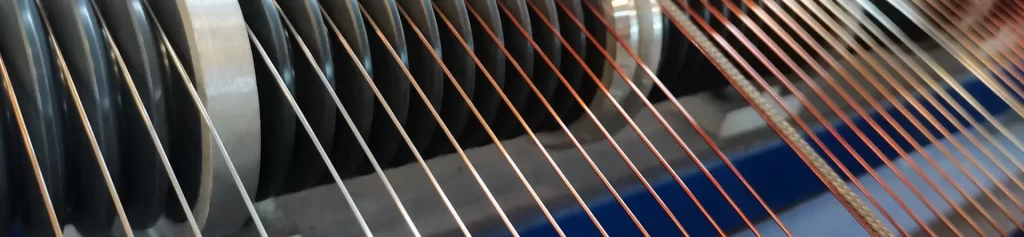
The requirements for the mechanical strength of enameled wire in large-scale motor windings are far higher than those for conventional industrial motors. This is due to the combined effect of wire diameter, operating speed, and electromagnetic force pulsation. In large synchronous motors, traction motors, and large hydro-generators of 2 MW and above, the nominal diameter of a single conductor in the stator slot generally falls between 1.0 mm and 3.0 mm, with hundreds of turns in a single slot and end overlap often exceeding 2 m. During winding and insertion, the conductor undergoes multiple mechanical loading processes, including payoff eye guidance, tension constraint, slot arrangement, and slot wedge clamping. During operation, it continuously endures the combined effects of alternating electromagnetic force, fundamental frequency vibration, and thermal cycling. Mechanical failure in any of these stages can lead to a local inter-turn short circuit, which may then develop into a phase-to-phase breakdown or grounding fault, ultimately forcing the entire stator winding to be repaired or replaced.
The mechanical strength of an enameled wire is not a single indicator, but rather a product of three independent physical capabilities. The tensile strength and ductility of the conductor substrate determine whether the wire will break under tension; the adhesion between the enameled coating and the substrate determines whether bending strain can be effectively transferred; and the abrasion resistance of the enameled coating surface determines whether the wire will lose its insulation layer during crossings, friction, and compression within slots. If any of these three capabilities fails, the mechanical strength becomes zero. A common bias in engineering judgment is equating conductor tensile strength directly with winding mechanical strength, leading to misjudgment during wire selection.
This article, based on the general requirements of IEC 60317-0-1, the IEC 60317 series, NEMA MW 1000, and ASTM B8 standards, and considering the actual operating conditions of large motors , systematically explains the three dimensions of mechanical strength, the applicable range of standard mechanical indicators, key points of testing methods, and selection paths. Some of the mechanical values listed in this article are derived from publicly available standard provisions and manufacturing inspection records.
The three independent dimensions of mechanical strength
Conductor Substrate: the inseparability of tensile strength and ductility
The conductor substrate bears the entire tensile load. Physically, tensile strength and elongation are two sides of the same coin—purchasing higher tensile strength necessarily means accepting lower elongation. They are not parameters that can be selected independently.
According to IEC 60317-0-1, the elongation of copper wire conductors with enamel increases with increasing nominal diameter. The required value is 5% for a diameter of 0.018 mm, rising to 38% for a diameter of 5.000 mm. This trend stems from the correlation between the degree of work hardening during cold drawing and the wire diameter. Thinner wires experience more extensive strain accumulation and more severe lattice deformation within the wire drawing die, thus shifting the ratio of ductility to strength towards strength.
The typical mechanical fit of large motors in the wire diameter range is as follows:
| Nominal diameter (mm) | Corresponding AWG specifications | Fracture elongation requirements | Engineering meaning |
|---|---|---|---|
| 0.500 | 24 | Approximately 6% | With limited buffering capacity, winding tension must be strictly controlled. |
| 1.000 | 20 | Approximately 9% | Large motors typically use a lower limit, and the buffer margin becomes more ample. |
| 1.600 | 16 | Approximately 11% | Regular insertion interval |
| 2.000 | 14 | Approximately 12% | Large motors mainly use the wire diameter range |
| 3.000 | 11 | Approximately 14% | End overlap section and formed coil |
| 5.000 | 5 | 38% | Special formed coil and low-frequency high-current winding |
The above elongation values are typical limit levels in the standard table; specific determinations should be based on the corresponding clauses of the current standard version. The trend presented in the table is the basis for selection judgment—the thicker the wire diameter, the larger the available ductility buffer space.
Enamel Adhesion: The Interface for Stress Transfer
The adhesion of the enamel determines the distribution ratio of bending stress between the substrate and the coating layer. When the adhesion is insufficient, the bending strain acts directly on the interface between the enamel and the substrate, causing the enamel to crack or peel off at low strain levels.
It is worth noting that the hard-drawn conductor compresses this buffer space in the opposite direction. The tensile strength in the hard-drawn state can reach 455–460 MPa, while the elongation decreases simultaneously to 1.0%–1.5%. Within this range, the conductor substrate almost loses its ductility buffering capacity, and the bending strain during the winding process is entirely borne by the enamel. The functional attribute of the enamel thus changes from a passive protective layer to the sole stress-absorbing layer, and the requirements for adhesion and abrasion resistance performance rise accordingly.
Large motors employ rigid slot wedges for end-binding and fastening. The conductors are compressed within the slots and subjected to tension from the binding tape at the ends; both loads are transmitted through the enamel interface. Typical manifestations of insufficient enamel adhesion include longitudinal cracks in the conductor coating at the slot opening and annular erosion in the end-binding area.
Enamel Abrasion Resistance Capability: Surface Protection during Winding and Operation
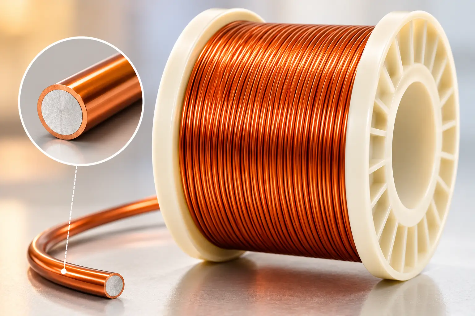
Abrasion resistance measures the ability of an enamel to maintain its insulating integrity under continuous mechanical friction. The test method is a reciprocating scratch test, in which a scraper is moved back and forth across the enamel surface under specified pressure, and the number of times and the force value are recorded when the enamel is worn through and conductive contact occurs.
IEC 60317-20’s specifications for solderable Polyurethane/enamel-coated copper wire serve as a typical example. Within the nominal diameter range of 0.250 mm to 0.800 mm, the minimum average breaking force for Grade 1 increases from 2.30 N to 4.50 N, with a single-measurement minimum breaking force ranging from 1.95 N to 4.40 N; the corresponding values for Grade 2 are 1.95 N to 5.45 N and 1.60 N to 6.20 N. The standard limits for abrasion resistance vary significantly with the enamel thickness grade; Grade 2 enamel coatings, even with thicker coatings, exhibit a higher lower limit for single-measurement breaking force.
The abrasion resistance specifications for polyvinyl acetal (enameled wire) cover the range of 0.250 mm to 2.500 mm, with minimum average breaking force and minimum single-blow breaking force specified for three enamel thickness grades: Grade 1, Grade 2, and Grade 3. This standard data indicates that while thicker enamel coatings result in higher electrical breakdown voltage, their mechanical surface strength is also simultaneously improved.
Polyamide-imide enameled wire ranks among the top in terms of mechanical abrasion resistance among all enamel types. Related product data indicates that its enamel surface is hard and smooth, with significantly better abrasion resistance and tensile adhesion than ordinary polyester and polyester imide systems. Its softening breakdown temperature is typically above 330 °C to 350 °C, and it exhibits extremely low internal stress without cracking under sudden thermal shocks exceeding 200 °C.
Three-dimensional failure independence
Conductor breakage, enamel peeling, and enamel scratching are three independent failure modes, each with different triggering conditions and testing methods. Confusing these three will lead to systematic omissions in selection and verification.
| Dimension | Physical carrier | Dominant Failure Mode | Standard verification methods |
|---|---|---|---|
| Conductor substrate | Tensile load | Tensile fracture, necking fracture | Tensile test (ASTM B1 / B8) |
| Enamel adhesion | Interface transfer of bending strain | Peeling, longitudinal cracking | Bending test, peel test |
| Enamel abrasion resistance | Surface friction | Wear through to expose copper | Reciprocating scratch test |
Sources of mechanical loads under large motor operating conditions
Loads during the winding and insertion phases
The insertion process is the stage with the highest density of mechanical damage. The conductors within a slot must be arranged within a limited slot size; the slot fill factor is typically designed to be between 0.45 and 0.55, leaving insufficient clearance to accommodate the minute deformations and displacements of the conductors under stress. The conductors are constrained by the bending radius at the slot entry bend, and the enamel at the slot opening corner is subjected to both bending and scratching.
The wedge clamping process in the slot creates radial compression on the conductors within the slot. The compression load is positively correlated with the slot fill factor; the higher the slot fill factor, the greater the contact pressure between the conductors, and the higher the risk of mutual scratching between the enamel coatings.
End processing is another high-load stage. The ends need to be bent, bound, and insulated. During bending, the conductor is subjected to tension on the outside and compression on the inside, with tensile cracking of the outer enamel being a common failure mode. The overlap length at the ends can reach several meters in large motors, and uneven distribution of binding tape tension along the length can cause localized stress concentrations.
Load during operation
The mechanical load during the operation phase is different in nature from that during the winding phase; it is a periodic, stable-amplitude alternating load.
The electromagnetic force acts radially and tangentially within the rotor, and its amplitude is proportional to the square of the current. Under normal operating conditions, the motor typically operates at 60% to 80% of its rated torque. Torque pulsation is caused by tooth effect, load fluctuations, and power supply harmonics. The frequency of the electromagnetic force pulsation caused by torque pulsation is directly related to the number of rotor teeth, and the typical frequency can reach several hundred hertz.
Electromagnetic force pulsations superimposed on fundamental frequency mechanical vibrations cause minute relative motions in the conductor within the slot. The minute reciprocating friction between the conductor and the slot wall, and between conductors themselves, continuously depletes the enamel thickness. This loss mechanism gradually manifests after the motor has operated for hundreds of thousands of hours, exhibiting an imbalance in the stator, winding, and DC resistance, accompanied by a localized temperature rise.
Thermal cycling constitutes a third type of load source. During motor start-up and shutdown, the temperature fluctuates within a range of tens of degrees Celsius. The thermal expansion coefficients of the copper substrate and the enamel do not match, resulting in periodic shear stress at the interface. After hundreds to thousands of thermal cycling cycles, microcracks may appear in the enamel, which can propagate into through-hole defects under vibration conditions.
Furthermore, there is a risk of partial discharge in the electromagnetic environment. Under variable frequency drive power supply conditions, the rate of increase of the impulse voltage in the insulation system can reach 1 kV/μs to 5 kV/μs. High-frequency components can induce partial discharge at micro-defects in the enamel, and the chemical reactions resulting from this partial discharge can accelerate the degradation of the enamel. At this point, defects in the enamel caused by insufficient mechanical strength become the starting point for electrochemical degradation.
Correspondence between enamel type and mechanical properties
Mechanical property positioning of each enamel type
The ranking of mainstream enamel types in terms of mechanical properties is not entirely consistent with their ranking in terms of heat resistance. Polyurethane systems have a relatively low thermal class and moderate mechanical properties; polyester and polyester imide systems achieve a balance between heat resistance and mechanical properties; and polyester/polyamide-imide and polyamide-imide systems perform best in terms of mechanical properties.
| Enamel type | Typical thermal class | Mechanical performance positioning | Applicability of large motors |
|---|---|---|---|
| Polyurethane (PU) | 130 °C | Moderate, with neither adhesion nor abrasion resistance being particularly strong. | Not recommended for use with large motors |
| Solderable Polyurethane (PU) | 155 °C | Above average, with good solderability. | End welding connectors are applicable |
| Polyester (PEW) | 155 °C | Good, with obvious cost advantages | Mainstream choice for conventional large motors |
| Polyesterimide (PEI) | 180 °C | Good, with both heat resistance and a certain degree of abrasion resistance. | Large motors operating in high-temperature conditions |
| Polyester Polyamide-imide (EIW) | 200 °C | Excellent, with outstanding abrasion resistance and adhesion. | Large motors are preferred |
| Polyamide-imide (PAI) | 220 °C | Best, abrasion resistance has the strongest performance | First choice for high-demand occasions |
The advantages of the polyester polyamide-imide system in large motors stem from its double-layer structure design. The outer polyamide-imide layer provides the mechanical function of a high-strength enamel, while the inner polyester layer offers good flexibility and process buffering, allowing the overall system to maintain high abrasion resistance while still accommodating wire bending.
Standard system comparison
The correspondence between the enamel type and international standards is as follows. When selecting a type, the current version of the cited clauses must be confirmed:
| enamel type | IEC Standard | NEMA Standard | Federal regulations |
|---|---|---|---|
| Polyvinyl Formal (PVA) | 60317-1 (round wire) | MW 15 | JW 1177/14 |
| Polyvinyl Formal adhesive type | 60317-5 | MW 19 | JW 1177/6 |
| Polyurethane | 60317-20 | MW 79 | JW 1177/41 |
| Polyurethane adhesive type | 60317-35 | MW 131 | — |
| Polyesterimide | 60317-8 | MW 30 | JW 1177/12 |
| polyester polyamide-imide | 60317-13 | MW 73 | — |
| Polyesterimide bonding type | 60317-20 | MW 102 | — |
| Polyimide | 60317-46 (round wire) | MW 16 | JW 1177/15 |
Table 50 of NEMA MW 1000-2018 specifies the requirements for reducing the residual resistance of round wire/magnet wire after scratching, covering the MW 5, 9, 15, 17, 24, 28, 30, 35, 72, 73, 74, 76, 80, 81, and 8359 series. This table does not address the number of times the enamel is scratched through, but rather the residual resistance level of the magnet wire after scratching, examining the loss of effective conductive area due to enamel damage and conductor deformation.
Fitting the springback angle with the wire diameter
The springback angle reflects the conductor’s ability to return to its original shape after winding; a smaller value indicates a higher ductility deformation ratio and easier subsequent shaping. IEC 60317-0-1 specifies springback angle limits for diameters ranging from 0.080 mm to 1.600 mm.
| Nominal diameter (mm) | Grade 1 Maximum springback angle | Max Springback Angle, Grade 2 and Grade 3 |
|---|---|---|
| 0.080–0.160 | 70° to 59° | 80° to 67° |
| 0.180–0.500 | 54° to 28° | 62° to 32° |
The springback angle limit increases with increasing diameter and also increases with increasing enamel thickness. Large motors commonly use wire diameters ranging from 1.0 mm to 3.0 mm, which falls outside the range covered by the table above and must be determined according to the relevant clauses of the standard.
Mechanical testing methods and judgment criteria
Specifications for tensile testing
Differences in tensile test values often stem from testing conditions rather than the material itself. Before comparing tensile strength data from different sources, the following conditions must be verified to ensure consistency.
The choice of gauge length directly determines the elongation reading. Hard-drawn copper wire systems use a 10-inch (250 mm) gauge length, while some systems use a 50 mm gauge length; the elongation values of these two systems cannot be directly compared. Ignoring the gauge length difference when referencing data across standards can result in errors of several percentage points.
The tensile rate affects the measurement results. Excessive rates can cause the material to fracture before it has fully deformed, resulting in a lower reading. ASTM B1 and B8 systems specify a tensile speed not exceeding 3 in/min, or 75 mm/min.
The retest rule determines the fairness of the judgment. If the initial test fails, two additional specimens are taken, and the average of the three results is used as the judgment value. The significance of this rule is that hard-drawn materials tend to be brittle, and the probability of a single specimen failing due to clamping damage or improper sampling position is not low. Disqualifying a single specimen based solely on its appearance would inadvertently disqualify qualified lots.
Sampling and Data Validity
Several details in the testing process can directly affect the validity of the data and must be controlled at the sampling stage.
The breaking point must fall within the effective gauge length. Specimens falling within the clamping section or clamping transition zone should be listed separately and not included in the statistics. Post-fracture measurements must maintain the fracture surfaces in contact; clamp displacement must not be included in the elongation results. The verification area must be taken from the actual measured dimensions of this single-line test, and nominal values must not be applied. Resistivity measurements must maintain the actual delivered cross-section of the test section; it is not permissible to stretch the section to a regular shape before measurement.
Samples should be taken from different locations on the same spool of wire, and each sample should be recorded with its own diameter measurement and mechanical number. It is not advisable to mix samples and calculate a single average. Mixing samples will mask the differences in manufacturing conditions, which are often significant in the procurement of long coils for large motors.
High strength and low elongation can serve as clues for investigating processing conditions, but they are not sufficient on their own to prove that there is an anomaly in a certain wire drawing process.
Scratch test and thermal shock test
The results of the abrasion resistance test are affected by the material of the scraper, the pressure, and the reciprocating frequency. Cross-laboratory comparisons require confirmation that the test conditions are consistent. IEC 60317-20 specifies a test range of 0.250 mm to 0.800 mm for nominal diameters; for wire diameters exceeding 0.800 mm, the abrasion resistance performance usually needs to be determined according to the specific clauses of the enamel type.
Thermal shock testing examines the cracking tendency of the enamel under sudden temperature changes. IEC 60317-0-1 specifies that mandrels with diameters of 0.140 mm and below should be as listed in the table, mandrels with diameters from 0.160 mm to 1.600 mm should be from 0.250 mm to 5.000 mm, and conductors with diameters exceeding 1.600 mm must withstand 25% elongation without cracking of the enamel.
The thermal shock requirements for wires used in large motors are typically higher than those for general applications because these motors vary significantly in operating temperature, start-stop frequency, and cooling conditions. The non-cracking properties of polyester/polyamide-imide and polyamide-imide/enamel coatings under thermal shock above 200 °C are a key reason for their widespread use in the field of large motors.
Insulation continuity and breakdown voltage
Mechanical damage ultimately manifests as insulation defects, therefore insulation continuity constitutes the final verification step for mechanical strength. For conductors with a diameter not exceeding 1.600 mm, IEC 60317-0-1 specifies the upper limit for the number of defect points per 30 m length: 5 to 40 for Grade 1 and Grade 1B (divided by diameter), 3 to 10 for Grade 2 and Grade 2B, and 2 to 5 for Grade 3.
Breakdown voltage requirements are graded by both enamel thickness and conductor diameter. For diameters ranging from 0.112 mm to 2.500 mm, Grade 1 is 1300 V to 2700 V, Grade 2 is 2700 V to 5000 V, and Grade 3 is 3900 V to 7600 V. Large motors typically operate at voltages between 6 kV and 13.8 kV; therefore, inter-turn insulation assessment relies on winding inter-turn withstand voltage tests and partial discharge measurements, rather than the breakdown voltage of a single conductor.
The temperature index of the insulation material shall be determined according to the IEC 60172 method, and the minimum service life required by the standard is 5000 hours. All mechanical and electrical performance tests shall be equilibrated at a temperature of 15 °C to 40 °C and a relative humidity of 25% to 75%.
Selection Decision Framework
The selection process can be carried out by following these steps.
The first step is to define the operating condition boundaries. The motor capacity class, voltage class, cooling method, start-stop frequency, vibration and shock conditions of the operating environment, and winding type (lapped or wave-wound, formed coil or embedded) all need to be confirmed first. The thermal class and mechanical strength requirements are derived from this, rather than being deduced backwards from the specifications.
The second step is to determine the wire diameter and conductor condition. For large motors, the wire diameter typically ranges from 1.0 mm to 3.0 mm. It is necessary to verify whether the corresponding elongation value meets the winding process requirements. The conductor condition is selected between annealed and semi-hard drawn; if elongation is acceptable at 8% or more, semi-hard drawn is usually sufficient, and hard drawn is unnecessary.
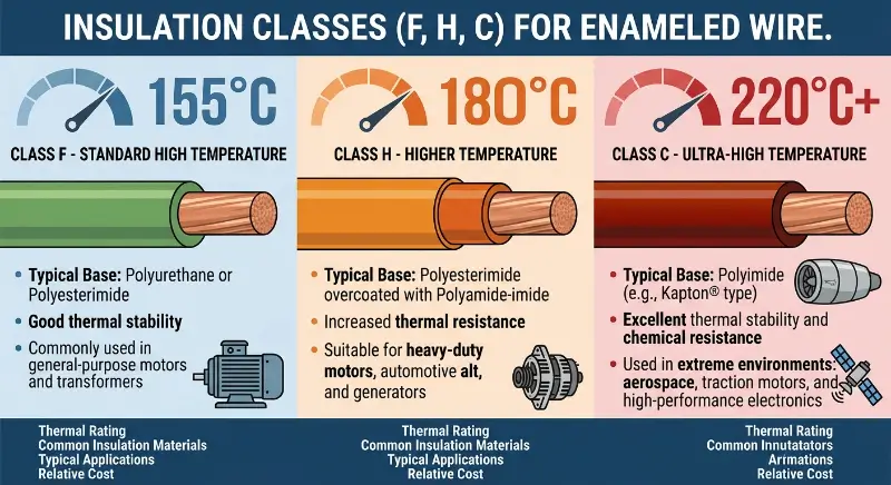
Step 3: Matching the enamel type. The thermal class is the primary constraint, and mechanical properties are the secondary constraint. Under normal large motor operating conditions, polyester imide offers a comprehensive advantage in terms of cost and performance; under high temperature or high vibration conditions, a shift towards polyester imide and higher grades is needed; when there are special requirements for abrasion resistance, the enamel thickness must be increased accordingly. Due to thermal class limitations, the Polyurethane system is generally not suitable for the main winding of large motors.
Step 4: Verify the process window. Check whether the payoff tension, drum speed, wire payoff eye radius, and arrangement accuracy of the winding equipment are suitable for the selected wire specifications, and whether the pre-coating treatment and curing curve match the enamel type. Before this is confirmed, the conclusions of the previous three steps are not feasible. Large motors have longer single wire lengths and more end bends, requiring a higher margin in the process window than conventional motors.
Step 5: Write the mechanical properties in pairs in the specifications document. Tensile strength and elongation must be agreed upon in pairs, and the sampling location, gauge length, and retesting rules must be noted. Abrasion resistance, adhesion, thermal shock, and insulation continuity should be selected and included based on the specific winding type.** Upon arrival, a verification test should be performed; the measured value of elongation is an irreplaceable verification item.
Typical application scenarios
Large hydro-generators—characterized by low rotational speed but large diameter, numerous conductors within a single slot, and long end overlap. During operation, they are subjected to low-frequency, high-amplitude electromagnetic forces, making mechanical fatigue a primary concern. Both polyester imide and polyester polyamide-imide are suitable, and the matching relationship between the end-binding process and the conductor’s mechanical strength is a key design consideration.
Traction motors and large drive motors—operating at high speeds and high torques, with high electromagnetic force pulsation frequency and high vibration intensity. The abrasion resistance and long-term thermal cycling tolerance of the enamel form the main selection criteria; thicker enamel grades paired with high-strength enamel types are common configurations.
Large synchronous generators and industrial drive motors – operate under continuous conditions with stable temperatures but long service life. The number of thermal cycling cycles is relatively low; enamel and insulation continuity are primary considerations, and polyester systems offer a cost advantage.
Large water pumps and mining motors—Environmental vibration and shock conditions are harsh, leading to significant fluctuations in the quality of end binding and slot wedge tightening processes. These operating conditions demand higher-than-average consistency upon delivery, necessitating more frequent random checks and verifications of mechanical performance.
Common Selection Mistakes
Using only tensile strength to determine mechanical strength—tensile strength only covers the conductor substrate dimension and does not reflect enamel adhesion and abrasion resistance. All three must be verified separately.
Ignoring the relationship between elongation and enamel—When using conductors with extremely low elongation, the bending strain is entirely borne by the enamel. The requirements for the enamel type must be increased accordingly; otherwise, the high-strength conductor may become a source of breakage.
Mechanical reinforcement should only be considered after meeting electrical requirements with a thin enamel. The enamel thickness grade determines both breakdown voltage and abrasion resistance; these are the same variable. Increasing the enamel grade improves both performance aspects simultaneously.
The resistance index after scratching in NEMA MW 1000 Table 50 is mistakenly taken as the number of times it is scratched through. This table assesses the level of residual resistance after scratching, which is not in the same dimension as the destructive force index of the reciprocating scratch test, and the two cannot be substituted for each other.
Using a single specimen to determine the qualification of hard-drawn or semi-hard drawn materials — These materials have a high probability of accidental failure with a single specimen and must be subject to the retest rule.
Conclusion
Mechanical strength is a combination of three independent capabilities, not a single indicator. The tensile strength of the conductor substrate, the adhesion of the enamel, and the abrasion resistance of the enamel together constitute effective mechanical strength. If any one of these capabilities fails, the overall indicator returns to zero.
Technically significant indicators are paired and combined indicators, namely the joint agreement of tensile strength and elongation, accompanied by a matching confirmation of enamel grade. Once this set of indicators is determined, the conductor condition, enamel type, winding process parameters, and delivery verification plan can all be derived. Conversely, if this set of indicators is not determined, subsequent selection discussions will lack a valid basis.
The design margin for the mechanical strength of large motors should ultimately be reflected in the coordination of three aspects: the selection of the winding type, the design of the end fixing, and the operation and maintenance procedures, rather than being limited to the technical parameters of the conductor itself.