


1 Introduction
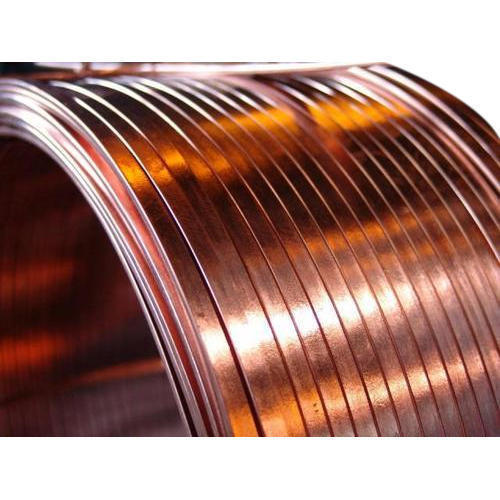
Flat enameled copper wire slot utilization optimization scheme selection starts with the fact that flat enameled copper wire, also known as flat enameled copper wire, is the key winding material for high power, high power density, and high efficiency electrical equipment. Flat enameled copper wire is increasingly used in new energy vehicle drive motors, rail transit traction motors, wind power generation, special transformers, large industrial motors, superconducting magnets, robot servo motors, home appliance variable frequency motors, and other scenarios. The core advantages of flat enameled copper wire are high slot fill factor, large power density, high efficiency, low copper loss, and good mechanical strength, which is the key technology for the design and manufacture of high power density electrical systems.
Slot fill factor is the core parameter of flat enameled copper wire winding design, which directly affects the motor power density, efficiency, temperature rise, vibration noise, reliability, and other key performance indicators. Slot fill factor optimization is the key technical issue of flat enameled copper wire winding design. This article, based on IEC 60317, NEMA MW 1000-2018, IEC 60034, and ASTM B 49 international standards, systematically describes the technical methods and engineering practice of flat enameled copper wire slot fill factor optimization from eight dimensions including slot fill factor basic theory, flat enameled copper wire conductor form, insulation structure, winding process, heat dissipation optimization, electrical performance optimization, application scenarios, and typical cases, providing systematic technical reference for the design and manufacture of high power density electrical systems.
2 Slot Fill Factor Basic Theory
2.1 Slot Fill Factor Definition
Slot fill factor is a parameter to measure the filling degree of conductors in stator slots or rotor slots, defined as the ratio of the total cross-sectional area of conductors in the slot to the effective cross-sectional area of the slot, usually expressed as a percentage. The slot fill factor calculation formula: slot fill factor equals the total cross-sectional area of conductors divided by the effective cross-sectional area of the slot multiplied by 100%.
Slot fill factor includes pure conductor cross-sectional area and conductor enamel film cross-sectional area. The pure conductor slot fill factor only calculates the bare conductor cross-sectional area, and the enamel film slot fill factor calculates the total cross-sectional area of conductors including the enamel film. In engineering, the enamel film slot fill factor is usually used as the design and calculation basis.
2.2 Slot Fill Factor Classification
Based on conductor form, winding slot fill factor can be divided into the following types:
Round conductor single layer winding slot fill factor: Round conductor single layer winding slot fill factor is usually 35% to 50%, suitable for general small and medium motors and transformers.
Round conductor double layer winding slot fill factor: Round conductor double layer winding slot fill factor is usually 45% to 60%, suitable for medium and large motors.
Flat conductor single layer winding slot fill factor: Flat conductor single layer winding slot fill factor is usually 50% to 65%, suitable for compact motors.
Flat conductor double layer winding slot fill factor: Flat conductor double layer winding slot fill factor is usually 60% to 75%, suitable for high power motors.
Flat conductor multi-layer winding slot fill factor: Flat conductor multi-layer winding slot fill factor is usually 70% to 80%, suitable for high power density motors.
Hairpin flat winding slot fill factor: Hairpin flat conductor winding slot fill factor is usually 75% to 85%, which is the winding structure with the highest slot fill factor currently.
2.3 Slot Fill Factor Influence
The influence of slot fill factor on winding performance is mainly reflected in the following aspects:
Power density influence: For every 10% increase in slot fill factor, motor power density increases by approximately 5% to 8%. This is because an increase in slot fill factor means that under the same slot volume, the conductor cross-sectional area increases, the current capacity increases, and the output power increases.
Efficiency influence: After slot fill factor increases, the conductor cross-sectional area increases, the resistance decreases, the copper loss decreases, and the motor efficiency increases. For every 10% increase in slot fill factor, the efficiency increases by approximately 0.5% to 1%.
Temperature rise influence: After slot fill factor increases, the conductor heat dissipation area increases, the heat dissipation path shortens, and the winding temperature rise decreases. For every 10% increase in slot fill factor, the temperature rise decreases by approximately 3 to 5 K.
Mechanical performance influence: After slot fill factor increases, the conductors are more closely arranged in the slot, the winding mechanical strength increases, and the vibration resistance is enhanced. However, an excessively high slot fill factor will increase the difficulty of the insertion process and may damage the enamel film.
Process difficulty influence: After slot fill factor increases, the difficulty of the insertion process increases significantly. When the slot fill factor exceeds 80%, the insertion qualification rate decreases significantly, and the insertion cost increases.
Manufacturing cost influence: After slot fill factor increases, the material cost per unit of power decreases, the winding structure is more compact, and the overall weight is reduced. However, the material cost of flat conductors is slightly higher than that of round conductors, and the enamel film coating process is more complex.
2.4 Slot Fill Factor Limiting Factors
The slot fill factor of flat enameled copper wire windings is limited by the following factors:
Slot insulation thickness: Slot insulation includes slot bottom insulation, slot side insulation, slot opening insulation, inter-layer insulation, and slot wedge. The thicker the slot insulation, the smaller the effective slot cross-sectional area, and the lower the upper limit of slot fill factor.
Conductor enamel film thickness: The thicker the conductor enamel film, the larger the conductor outer diameter, the fewer conductors filled in the slot, and the lower the upper limit of slot fill factor. In engineering, the thinnest possible enamel film should be selected under the premise of allowing dielectric strength.
Conductor aspect ratio: The greater the conductor aspect ratio, the flatter the conductor cross-section, the higher the space utilization rate in the slot, and the higher the upper limit of slot fill factor. However, an excessively large aspect ratio will reduce the conductor rigidity and affect the insertion process.
Insertion process: The level of insertion process directly affects the achievable slot fill factor. High precision automatic insertion can achieve higher slot fill factor.
Conductor tolerance: The larger the conductor dimensional tolerance, the larger the gap in the slot, and the lower the actual slot fill factor. Selecting high precision flat conductors can increase the actual slot fill factor.
3 Flat Enameled Copper Wire Conductor Form
3.1 Cross-Section Shape
The cross-section shape of flat enameled copper wire is crucial for slot fill factor optimization.
Rectangular cross section: Standard rectangular cross section, with aspect ratio 1 to 20, mature process and wide universality, is the most commonly used flat conductor cross section shape.
Rounded rectangular cross section: The edge of the rectangular cross section adopts a rounded corner design, with corner radius 0.2 to 2.0 mm. The rounded corner design improves the electric field distribution, reduces the risk of enamel film damage, and improves the dielectric strength.
Chamfered rectangular cross section: The edge of the rectangular cross section adopts a small chamfer design, with chamfer size 0.1 to 0.5 mm. The chamfer design reduces the stress concentration of the enamel film.
Waist round cross section: The two ends of the waist round cross section are semi-arcs, and the middle is a straight line segment. The conductor rigidity of the waist round cross section is higher than that of the rectangle, and the uniformity of enamel film coating is better than that of the rectangle.
Trapezoidal cross section: The two sides of the trapezoidal cross section are inclined edges, and the trapezoidal cross section is convenient for insertion and manufacture, and is used in special scenarios.
3.2 Aspect Ratio Design
The aspect ratio W/T of flat enameled copper wire is a key parameter for slot fill factor optimization. Low aspect ratio 1 to 3 is close to square cross section, with high rigidity, easy insertion, and lower slot fill factor. Medium aspect ratio 3 to 8 is flat rectangular cross section, with moderate rigidity, medium insertion difficulty, and higher slot fill factor. High aspect ratio 8 to 20 is flat rectangular cross section, with lower rigidity, high insertion difficulty, and high slot fill factor. Ultra-high aspect ratio above 20 is extremely flat cross section, with low rigidity, extremely difficult insertion, and highest slot fill factor.
The recommended aspect ratio for slot fill factor optimization of flat enameled copper wire: compact motor selects 5 to 8, high power motor selects 4 to 10, Hairpin motor selects 6 to 12, special transformer selects 8 to 15.
3.3 Size Specification
The size specification of flat enameled copper wire should be determined based on factors such as current capacity, slot fill factor target, insertion process, and rigidity requirements.
Micro flat conductor: Width 1.5 to 4 mm, thickness 0.4 to 1.5 mm, cross-sectional area 0.6 to 6 square mm, suitable for small power motors and small transformers.
Small flat conductor: Width 3 to 8 mm, thickness 0.8 to 3.0 mm, cross-sectional area 2.4 to 24 square mm, suitable for small and medium motors and medium transformers.
Medium flat conductor: Width 6 to 14 mm, thickness 1.5 to 5.0 mm, cross-sectional area 9 to 70 square mm, suitable for large motors and traction motors.
Large flat conductor: Width 10 to 20 mm, thickness 2.5 to 8.0 mm, cross-sectional area 25 to 160 square mm, suitable for extra-large motors, wind power, and special transformers.
Extra-large flat conductor: Width 16 to 30 mm, thickness 4.0 to 10.0 mm, cross-sectional area 64 to 300 square mm, suitable for extra-large special transformers and superconducting magnets.
3.4 Corner Radius
The corner radius of flat enameled copper wire has an influence on both slot fill factor optimization and dielectric strength. Corner radius 0 to 0.2 mm is a sharp corner design, with uneven enamel film thickness, easy damage to enamel film during insertion, and low dielectric strength, which is not recommended. Corner radius 0.2 to 0.5 mm is a small corner radius design, with relatively uniform enamel film coating, good insertion process, and high dielectric strength. Corner radius 0.5 to 1.0 mm is the standard corner radius design, with uniform enamel film coating, good insertion process, and high dielectric strength, which is the recommended scheme. Corner radius 1.0 to 2.0 mm is a large corner radius design, with the most uniform enamel film coating, the best insertion process, and the highest dielectric strength, but the conductor utilization rate is slightly reduced.
The recommended corner radius for slot fill factor optimization of flat enameled copper wire: low voltage scenario selects 0.3 to 0.5 mm, medium high voltage scenario selects 0.5 to 1.0 mm, extra high voltage scenario selects 1.0 to 2.0 mm.
3.5 Dimensional Tolerance
The dimensional tolerance of flat enameled copper wire directly affects the actual slot fill factor. The width tolerance should be controlled within ±0.03 to ±0.10 mm, and high precision scenarios should be controlled within ±0.01 to ±0.03 mm. The thickness tolerance should be controlled within ±0.02 to ±0.05 mm, and high precision scenarios should be controlled within ±0.01 to ±0.02 mm. The corner tolerance should be controlled within ±0.05 to ±0.20 mm. The angle tolerance, the perpendicularity of adjacent edges should be controlled within ±0.3 to ±1.0 degrees.
For slot fill factor optimization of flat enameled copper wire, high precision flat conductors should be selected, with dimensional tolerance controlled within ±0.05 mm and surface roughness controlled within Ra 0.8 to Ra 1.6 μm, ensuring smooth insertion and stable slot fill factor.
4 Insulation Structure Optimization
4.1 Enamel Film System Selection
The enamel film system of flat enameled copper wire should be selected based on factors such as working temperature, voltage class, mechanical stress, and insertion process.
Polyester enamel film 130 to 155 degrees Celsius: Suitable for general small and medium motors and home appliance motors, standards IEC 60317-20, IEC 60317-21, IEC 60317-35.
Polyesterimide enamel film 180 degrees Celsius: Suitable for medium and large motors and traction motors, standards IEC 60317-8, IEC 60317-13.
Polyamide-imide enamel film 200 to 220 degrees Celsius: Suitable for high power density motors, wind power, and new energy vehicle drive, standards IEC 60317-15, IEC 60317-26.
Polyimide enamel film 240 degrees Celsius and above: Suitable for extra-high temperature, extra-high power special motors, standards IEC 60317-7, IEC 60317-46.
The slot fill factor optimization of flat enameled copper wire recommends polyesterimide overcoated with polyamide-imide double coat composite enamel film, Class H or N, with high dielectric strength, excellent heat resistance, and high mechanical strength, which is the standard enamel film system for high power density windings.
4.2 Enamel Film Thickness Optimization
The enamel film thickness of flat enameled copper wire directly affects the slot fill factor. The thicker the enamel film, the larger the conductor outer diameter, the fewer conductors filled in the slot, and the lower the upper limit of slot fill factor. However, if the enamel film is too thin, the dielectric strength is insufficient, the enamel film is easily damaged, and the reliability decreases.
Enamel film thickness optimization principle: Under the premise of allowing dielectric strength, select the thinnest possible enamel film to improve the slot fill factor.
Thin enamel film Grade 1: Film thickness 0.02 to 0.06 mm, minimum breakdown voltage 1500 to 7500 V, suitable for low voltage scenarios.
Heavy enamel film Grade 2: Film thickness 0.04 to 0.10 mm, minimum breakdown voltage 2350 to 12000 V, suitable for medium voltage scenarios.
Extra heavy enamel film Grade 3: Film thickness 0.06 to 0.13 mm, minimum breakdown voltage 3000 to 14000 V, suitable for high voltage scenarios.
The slot fill factor optimization of flat enameled copper wire recommends Grade 2 enamel film thickness, achieving a balance between dielectric strength and slot fill factor. Medium and high voltage scenarios can select Grade 3 enamel film thickness.
4.3 Slot Insulation Optimization
Slot insulation includes slot bottom insulation, slot side insulation, slot opening insulation, inter-layer insulation, and slot wedge. The thinner the slot insulation, the larger the effective slot cross-sectional area, and the higher the upper limit of slot fill factor.
Slot bottom insulation: Traditional slot bottom insulation adopts polyester film plus mica paper plus glass fiber cloth composite structure, with thickness 0.20 to 0.50 mm. The optimization scheme adopts single layer polyimide film, with thickness 0.10 to 0.25 mm.
Slot side insulation: Traditional slot side insulation adopts polyester film plus mica paper composite structure, with thickness 0.15 to 0.40 mm. The optimization scheme adopts single layer polyimide film or polyethylene naphthalate film, with thickness 0.075 to 0.20 mm.
Inter-layer insulation: Inter-layer insulation adopts polyester film plus mica paper plus glass fiber cloth composite structure, with thickness 0.15 to 0.30 mm. The optimization scheme adopts single layer polyimide film or polyester film, with thickness 0.05 to 0.15 mm.
Slot wedge: The slot wedge adopts epoxy resin board, polyester resin board, or glass fiber reinforced resin board, with thickness 1.0 to 3.0 mm. The optimization scheme adopts thin epoxy resin board or magnetic slot wedge, with thickness 0.8 to 2.0 mm.
The slot fill factor optimization of flat enameled copper wire recommends the thin slot insulation scheme, with total slot insulation thickness controlled within 0.30 to 0.50 mm, improving the effective slot cross-sectional area by 5% to 10%.
4.4 Inter-Phase Insulation Optimization
Inter-phase insulation is the insulation between different phase windings at the winding end. The thickness of inter-phase insulation affects the winding end size and manufacturing process.
Traditional inter-phase insulation adopts polyester film plus mica paper plus glass fiber cloth composite structure, with thickness 0.20 to 0.50 mm. The optimization scheme adopts single layer polyimide film or polyester film plus glass fiber cloth composite structure, with thickness 0.10 to 0.30 mm.
The slot fill factor optimization of flat enameled copper wire recommends the thin inter-phase insulation scheme, with inter-phase insulation thickness controlled within 0.15 to 0.30 mm, reducing the winding end size by 10% to 20%.
5 Winding Process Optimization
5.1 Insertion Method
The insertion methods of flat enameled copper wire windings include:
Manual insertion: Traditional insertion method, suitable for small batch, multi-variety, special structure windings. The insertion quality is affected by worker skills, with upper slot fill factor 60% to 70%.
Semi-automatic insertion: Adopts special insertion tools and positioning fixtures, suitable for medium batch, standardized structure windings. The insertion quality is relatively stable, with upper slot fill factor 65% to 75%.
Fully automatic insertion: Adopts numerical control insertion machine and automatic wire feeding system, suitable for large batch, standardized structure windings. The insertion quality is stable, with upper slot fill factor 70% to 80%.
Hairpin insertion: Adopts automatic forming, automatic insertion, and automatic welding process, suitable for new energy vehicle drive motor windings. The insertion efficiency is high, with upper slot fill factor 75% to 85%.
The slot fill factor optimization of flat enameled copper wire recommends fully automatic insertion or Hairpin insertion, ensuring insertion precision and improving the actual slot fill factor.
5.2 Insertion Process Parameters
The insertion process parameters of flat enameled copper wire windings directly affect the slot fill factor and enamel film integrity.
Insertion speed: The insertion speed of flat conductors should be lower than that of round conductors to avoid enamel film damage caused by high speed insertion. The recommended insertion speed is 0.5 to 2.0 m per minute, and the Hairpin insertion speed is 5 to 20 m per minute.
Insertion force: The insertion force of flat conductors should be controlled within 50 to 200 N to avoid enamel film damage caused by excessive insertion force. The Hairpin insertion force is controlled within 200 to 500 N.
Insertion temperature: The insertion temperature of flat conductors should be controlled at 20 to 50 degrees Celsius to avoid enamel film brittleness cracking caused by low temperature insertion. In low temperature scenarios, the conductor should be preheated to 30 to 50 degrees Celsius.
Insertion tension: The insertion tension of flat conductors should be controlled within 10 to 50 N to avoid conductor deformation or enamel film damage caused by excessive tension.
Slot wedge installation: The slot wedge installation should use special tools to ensure that the slot wedge is installed in place but does not damage the conductor enamel film. The slot wedge installation force is controlled within 30 to 100 N.
5.3 Insertion Quality Control
The insertion quality control items of flat enameled copper wire windings:
Enamel film integrity: After insertion, the enamel film integrity should be tested. The high voltage pinhole detector or dielectric loss test can be used, with test voltage 1000 to 3000 V.
Conductor position: After insertion, the position of the conductor in the slot should be tested. The conductor should be centrally arranged with uniform gap. The position deviation should be controlled within ±0.1 to ±0.3 mm.
Slot wedge tightness: After insertion, the slot wedge tightness should be tested. The slot wedge should be firm but not damage the conductor. The slot wedge tightness should be controlled within 50 to 150 N.
Winding resistance: After insertion, the DC resistance of the winding should be tested to ensure that the resistance value meets the design requirements. The resistance deviation should be controlled within ±2%.
Insulation resistance: After insertion, the winding insulation resistance should be tested. The insulation resistance should not be lower than 100 MΩ per kV of rated voltage.
5.4 Insertion Difficulties Solutions
Insertion difficulties and solutions of flat enameled copper wire windings:
Conductor deformation: The conductor may be deformed by mechanical force during insertion. The solution is to adopt high precision molds and guides, reduce insertion force, and control insertion speed.
Enamel film damage: The conductor enamel film may be damaged by mechanical stress during insertion. The solution is to adopt rounded corner design, strictly control insertion force, and adopt automatic insertion equipment.
Uneven conductor arrangement: The conductor may be unevenly arranged in the slot during insertion. The solution is to adopt positioning fixtures, insert one by one, and vibrate during insertion.
Slot fill factor not up to standard: After insertion, the actual slot fill factor may be lower than the design value. The solution is to select high precision flat conductors, strictly control dimensional tolerance, and adopt automatic insertion equipment.
6 Heat Dissipation Optimization
6.1 Heat Dissipation Path
The main heat dissipation paths of flat enameled copper wire windings:
Conductor to slot insulation: Conductor heat is transferred to slot insulation through the enamel film. The thermal resistance depends on the enamel film thickness and thermal conductivity. The thinner the enamel film, the higher the thermal conductivity, and the lower the thermal resistance.
Slot insulation to iron core: Slot insulation heat is transferred to the shell through the iron core. The thermal resistance depends on the slot insulation thickness and iron core thermal conductivity. The thinner the slot insulation, the higher the iron core thermal conductivity, and the lower the thermal resistance.
Iron core to shell: Iron core heat is transferred to the shell through convection and radiation. The thermal resistance depends on the contact quality between the iron core and the shell, the shell surface temperature, and the ambient temperature.
Winding end heat dissipation: The winding end dissipates heat through convection and radiation. The thermal resistance depends on the end surface area, air velocity, and end insulation thickness.
The heat dissipation strategy of flat enameled copper wire slot fill factor optimization: select thin enamel film and thin slot insulation to improve the heat conduction efficiency from conductor to iron core; expand the winding end surface area to improve the end convection heat dissipation efficiency; adopt water-cooled or oil-cooled windings to improve the comprehensive heat dissipation efficiency.
6.2 Enamel Film Heat Conduction
The thermal conductivity of enamel film has a significant influence on winding heat dissipation. The thermal conductivity of common enamel films: polyester enamel film 0.20 to 0.25 W per m per K, polyesterimide enamel film 0.20 to 0.30 W per m per K, polyamide-imide enamel film 0.25 to 0.35 W per m per K, polyimide enamel film 0.30 to 0.40 W per m per K.
Enamel film heat conduction optimization: Select enamel film systems with higher thermal conductivity. Polyimide enamel film has the highest thermal conductivity, followed by polyamide-imide. Add nano thermal conductivity fillers such as nano alumina and nano boron nitride to the enamel film, improving the thermal conductivity of the enamel film by 20% to 50%. The enamel film thickness should be minimized under the premise of allowing dielectric strength, reducing the thermal resistance of the enamel film.
6.3 Slot Insulation Heat Conduction
The thermal conductivity of slot insulation has a significant influence on winding heat dissipation. The thermal conductivity of common slot insulation: polyester film 0.20 to 0.30 W per m per K, polyimide film 0.30 to 0.40 W per m per K, mica paper 0.20 to 0.30 W per m per K, glass fiber cloth 0.25 to 0.35 W per m per K, epoxy resin board 0.30 to 0.50 W per m per K.
Slot insulation heat conduction optimization: Select slot insulation materials with higher thermal conductivity. Minimize the number of layers and thickness of slot insulation. Adopt composite slot insulation materials reinforced with thermal conductivity fillers.
6.4 Impregnation Varnish Heat Conduction
Impregnation varnish fills the gaps in the winding and improves the overall thermal conductivity of the winding. The thermal conductivity of common impregnation varnish: epoxy impregnation varnish 0.20 to 0.30 W per m per K, polyester impregnation varnish 0.20 to 0.25 W per m per K, silicone impregnation varnish 0.25 to 0.30 W per m per K.
Impregnation varnish heat conduction optimization: Select impregnation varnish with higher thermal conductivity. Add nano thermal conductivity fillers such as nano alumina and nano boron nitride to the impregnation varnish. Adopt vacuum pressure impregnation process to ensure that the impregnation varnish fully penetrates the internal gaps of the winding.
7 Electrical Performance Optimization
7.1 Conductor Resistance Optimization
Flat enameled copper wire conductor resistance optimization strategy:
Select high purity conductor: TU1 oxygen-free copper conductivity is not less than 101% IACS, TU2 oxygen-free copper conductivity is not less than 100% IACS, T2 standard electrolytic copper conductivity is not less than 100% IACS. It is recommended to select TU1 oxygen-free copper.
Control conductor cross-sectional area: Under the premise of allowing slot fill factor, select conductors with larger cross-sectional area to reduce conductor resistance. The resistance of large cross-sectional area conductors is about 30% to 50% of that of small cross-sectional area conductors.
Control conductor length: Optimize the winding structure, shorten the winding end length, and reduce the total conductor length. Winding end optimization can reduce the total conductor length by 10% to 20%.
Control conductor temperature: The conductor resistance increases with the increase of temperature, and the resistance temperature coefficient is about 0.00393 per degrees Celsius. Optimizing heat dissipation to reduce conductor temperature can reduce conductor resistance by 5% to 15%.
7.2 Skin Effect Optimization
Flat enameled copper wire has skin effect in high frequency scenarios, and the skin depth is related to frequency, conductor resistivity, and magnetic permeability.
Skin depth calculation: At 50 Hz, the copper conductor skin depth is about 9.3 mm. At 60 Hz, the copper conductor skin depth is about 8.5 mm. At 400 Hz, the copper conductor skin depth is about 2.1 mm. At 1000 Hz, the copper conductor skin depth is about 2.1 mm. At 10 kHz, the copper conductor skin depth is about 0.66 mm.
Skin effect optimization: In low frequency scenarios, the skin effect is not significant, and a single layer flat conductor design is sufficient. In medium frequency scenarios, the flat conductor thickness should be controlled to be less than 1.5 times the skin depth. In high frequency scenarios, the Litz wire structure should be adopted, with multiple thin wires stranded to reduce the skin effect.
7.3 Proximity Effect Optimization
Flat enameled copper wire has proximity effect in high frequency scenarios, and the proximity effect is related to the conductor spacing, frequency, and conductor size.
Proximity effect optimization: Increase the conductor spacing to reduce proximity effect loss. Adopt Litz wire structure with multiple thin wires distributed. Optimize the conductor arrangement to reduce the magnetic field coupling between adjacent conductors.
7.4 Dielectric Loss Optimization
The dielectric loss of flat enameled copper wire windings is related to the dielectric properties of enamel film, slot insulation, and impregnation varnish.
Dielectric loss optimization: Select enamel film with low dielectric loss angle. The polyimide enamel film dielectric loss tangent is about 0.005 to 0.010. Select slot insulation with low dielectric loss angle. The polyimide film dielectric loss tangent is about 0.003 to 0.008. Select impregnation varnish with low dielectric loss angle. The epoxy impregnation varnish dielectric loss tangent is about 0.010 to 0.020. Reduce the thickness of enamel film and slot insulation to reduce dielectric loss.
8 Application Scenarios and Typical Cases
8.1 New Energy Vehicle Drive Motors
New energy vehicle drive motors are the most important application scenario for slot fill factor optimization of flat enameled copper wire. Hairpin flat conductor winding is the current mainstream solution, with slot fill factor reaching 75% to 85%.
A certain model of permanent magnet synchronous drive motor: Rated power 200 kW, rated speed 16000 rpm, flat conductor specification width 6 mm, thickness 2.0 mm, aspect ratio 3.0, enamel film thickness 0.08 mm, slot fill factor 78%, power density 5.5 kW per kg, efficiency 97%.
A certain model of high power density drive motor: Rated power 350 kW, rated speed 18000 rpm, flat conductor specification width 8 mm, thickness 2.5 mm, aspect ratio 3.2, enamel film thickness 0.10 mm, slot fill factor 82%, power density 7.5 kW per kg, efficiency 97.5%.
8.2 Rail Transit Traction Motors
Rail transit traction motors are an important application scenario for slot fill factor optimization of flat enameled copper wire. The slot fill factor of traction motor flat conductor windings reaches 65% to 75%.
A certain model of subway traction motor: Rated power 250 kW, rated speed 3600 rpm, flat conductor specification width 8 mm, thickness 3.0 mm, aspect ratio 2.7, enamel film thickness 0.10 mm, slot fill factor 70%, overload capacity 2.5 times rated power, efficiency 96%.
A certain model of EMU traction motor: Rated power 600 kW, rated speed 4000 rpm, flat conductor specification width 10 mm, thickness 3.5 mm, aspect ratio 2.9, enamel film thickness 0.12 mm, slot fill factor 72%, overload capacity 2.2 times rated power, efficiency 96.5%.
8.3 Wind Power Generators
Wind power generators are a special application scenario for slot fill factor optimization of flat enameled copper wire. Wind power flat conductor windings need to cope with harsh conditions such as vibration impact, temperature changes, and humid environments.
A certain model of onshore wind power generator: Rated power 5 MW, rated speed 12 rpm, flat conductor specification width 10 mm, thickness 4.0 mm, aspect ratio 2.5, enamel film thickness 0.12 mm, slot fill factor 68%, protection level IP54, service life over 20 years.
A certain model of offshore wind power generator: Rated power 12 MW, rated speed 10 rpm, flat conductor specification width 12 mm, thickness 4.5 mm, aspect ratio 2.7, enamel film thickness 0.13 mm, slot fill factor 70%, protection level IP65, service life over 25 years.
8.4 Special Transformers
Special transformers are a traditional application scenario for slot fill factor optimization of flat enameled copper wire. The slot fill factor of special transformer flat conductor windings reaches 65% to 75%.
A certain model of high current rectifier transformer: Rated capacity 5000 kVA, rated voltage 10 kV, flat conductor specification width 12 mm, thickness 4.0 mm, aspect ratio 3.0, enamel film thickness 0.10 mm, slot fill factor 72%, efficiency 98.5%.
A certain model of electric furnace transformer: Rated capacity 8000 kVA, rated voltage 35 kV, flat conductor specification width 16 mm, thickness 5.0 mm, aspect ratio 3.2, enamel film thickness 0.13 mm, slot fill factor 75%, efficiency 98%.
8.5 Robot Servo Motors
Robot servo motors are a high precision application scenario for slot fill factor optimization of flat enameled copper wire. The slot fill factor of servo motor flat conductor windings reaches 70% to 78%.
A certain model of industrial robot servo motor: Rated power 7.5 kW, rated speed 6000 rpm, flat conductor specification width 4 mm, thickness 1.5 mm, aspect ratio 2.7, enamel film thickness 0.08 mm, slot fill factor 73%, power density 4.5 kW per kg, positioning accuracy 0.01 mm.
A certain model of collaborative robot servo motor: Rated power 3.0 kW, rated speed 8000 rpm, flat conductor specification width 3 mm, thickness 1.2 mm, aspect ratio 2.5, enamel film thickness 0.07 mm, slot fill factor 70%, power density 3.8 kW per kg, torque ripple lower than 2%.
8.6 Home Appliance Variable Frequency Motors
Home appliance variable frequency motors are a high volume application scenario for slot fill factor optimization of flat enameled copper wire. The slot fill factor of home appliance variable frequency motor flat conductor windings reaches 60% to 70%.
A certain model of variable frequency air conditioner compressor motor: Rated power 2.0 kW, rated speed 6000 rpm, flat conductor specification width 3 mm, thickness 1.5 mm, aspect ratio 2.0, enamel film thickness 0.08 mm, slot fill factor 65%, efficiency 92%.
A certain model of variable frequency washing machine motor: Rated power 0.5 kW, rated speed 12000 rpm, flat conductor specification width 2 mm, thickness 1.0 mm, aspect ratio 2.0, enamel film thickness 0.07 mm, slot fill factor 62%, efficiency 88%.
9 Future Development Trends
9.1 Flat Conductor Technology Evolution
Flat enameled copper wire technology continues to evolve, supporting the continuous improvement of slot fill factor.
Ultra-flat conductor: Ultra-flat conductor with aspect ratio 20 to 30, with slot fill factor up to 85% to 90%, but low rigidity and difficult insertion.
Composite conductor: Copper clad aluminum composite flat conductor, nickel-plated flat conductor, silver-plated flat conductor, improving the comprehensive performance of the conductor.
Special shape conductor: Waist round, oval, racetrack and other special shape conductors, balancing rigidity and slot fill factor.
High purity conductor: Ultra-high purity conductor with copper content above 99.99%, with conductivity exceeding 102% IACS.
9.2 Enamel Film Technology Evolution
The enamel film technology of flat enameled copper wire continues to evolve.
Ultra-thin enamel film: Ultra-thin enamel film technology reduces the enamel film thickness under the premise of ensuring dielectric strength, improving slot fill factor.
Nano-modified enamel film: Nano alumina, nano boron nitride, nano graphene oxide modified enamel film, improving the thermal conductivity and dielectric properties of enamel film.
Self-repairing enamel film: The enamel film can be automatically repaired after damage, improving the long term reliability of the enamel film.
Ultra corona resistant enamel film: Corona resistant enamel film improves the voltage impulse resistance of windings and extends the winding life.
9.3 Insertion Process Evolution
The insertion process of flat enameled copper wire continues to evolve.
Hairpin process: The Hairpin process continues to evolve. Flat wire Hairpin, flat wire multi-layer Hairpin, X-Pin, I-Pin continue to improve slot fill factor.
Automatic insertion: The precision of fully automatic insertion equipment continues to improve, and the upper limit of slot fill factor continues to increase.
Laser welding: Laser welding technology replaces resistance welding and copper welding, improving the end welding quality.
Online inspection: Online inspection technology monitors the insertion quality in real time, improving the insertion qualification rate.
9.4 Slot Fill Factor Optimization Intelligence
Slot fill factor optimization of flat enameled copper wire is deeply integrated with intelligent technology.
Simulation optimization: Slot fill factor simulation optimization based on finite element analysis, predicting the actual slot fill factor and performance.
Machine learning: Machine learning models based on historical data automatically recommend conductor specifications, enamel film thickness, and insertion process.
Digital twin: Winding digital twin model, real-time monitoring of winding performance and life.
Intelligent manufacturing: Intelligent manufacturing of flat conductor manufacturing, enamel film coating, and winding manufacturing in the whole process.
10 Conclusion
Flat enameled copper wire slot utilization optimization scheme confirms that slot fill factor optimization of flat enameled copper wire is the key technology for the design and manufacture of high power density electrical systems including new energy vehicle drive motors, rail transit traction motors, wind power generation, special transformers, robot servo motors, and home appliance variable frequency motors. Slot fill factor optimization of flat enameled copper wire is a systematic engineering of multi-dimensional collaborative optimization including conductor form, insulation structure, insertion process, heat dissipation optimization, and electrical performance optimization.
Conductor form optimization includes key parameters such as cross-section shape, aspect ratio, size specification, corner radius, and dimensional tolerance. Insulation structure optimization includes key parameters such as enamel film system, enamel film thickness, slot insulation, and inter-phase insulation. Insertion process optimization includes key links such as insertion method, process parameters, quality control, and difficult problem solutions. Heat dissipation optimization includes key parameters such as heat dissipation path, enamel film heat conduction, slot insulation heat conduction, and impregnation varnish heat conduction. Electrical performance optimization includes key parameters such as conductor resistance, skin effect, proximity effect, and dielectric loss.
Application scenarios cover new energy vehicle drive motors, rail transit traction motors, wind power generators, special transformers, robot servo motors, home appliance variable frequency motors, and other fields. Each application scenario has unique requirements for slot fill factor and optimization strategy, requiring optimized design based on specific scenarios.
With the continuous evolution of flat conductor technology, enamel film technology, insertion process, and slot fill factor optimization intelligence, the slot fill factor and comprehensive performance of flat enameled copper wire windings will be further improved, providing strong support for the development of strategic emerging industries including new energy vehicles, rail transit, wind power, intelligent manufacturing, smart home appliances, and superconductivity.
Contact Information: E-mail office@cnlpzz.com, WhatsApp 0086-19337889070, Zhengzhou LP Industry Co., Ltd.
Contact Information:
- E-mail: office@cnlpzz.com
- WhatsApp: 0086-19337889070
- Zhengzhou LP Industry Co., Ltd.