


1 Introduction
As a core component of the global renewable energy infrastructure, wind turbine generators face stringent requirements for their winding insulation systems due to their operating environment. Wind turbines are typically deployed in wind-rich areas—mountains, deserts, offshore, and near-shore intertidal zones—enduring multiple stresses including strong winds, wide-temperature circulation, humid salt spray, vibration, and frequent start-stop cycles. Conventional single-stranded wind turbines are prone to insulation aging, inter-turn short circuits, and premature failure in such environments, significantly reducing power generation and operational economics.
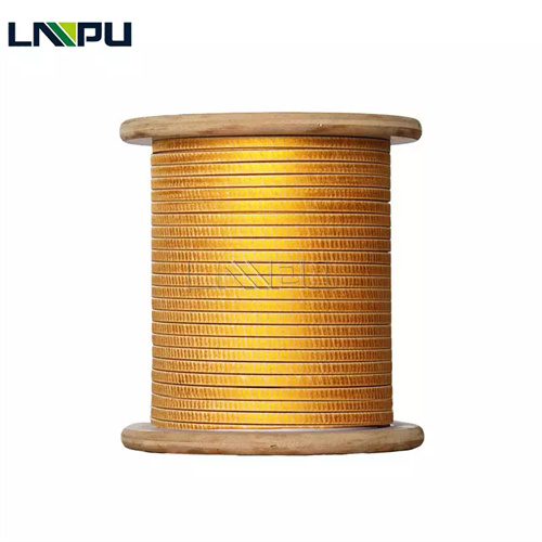
Fiberglass Covered Wire (FGCW), with its multi-layered dielectric composite structure of conductor, enamel coating, glass fiber, and impregnation varnish, provides wind turbines with comprehensive improvements in heat resistance, mechanical properties, moisture resistance, and vibration resistance. This article, based on standards and specifications such as ANSI/NEMA MW 1000-2018, IEC 60317-48, IEC 61400-1, and GB/T 19960, discusses this topic from five dimensions: application scenarios, insulation systems, technical requirements, typical applications, and selection evaluation. It primarily serves the design and procurement of doubly-fed induction generators (DFIG), direct-drive permanent magnet synchronous generators (PMSG), semi-direct-drive units, yaw and pitch motors, transformers, and auxiliary motors within the nacelle.
2 Engineering Requirements for Wind Turbine Winding Insulation
The winding insulation system of a wind turbine must simultaneously meet the following multiple requirements:
- **Heat Resistance and Thermal Life:** Wind turbines are typically designed for a lifespan of 20-25 years, with winding operating temperatures constrained by Class F (155 °C) or Class H (180 °C) insulation systems. According to Montsinger’s rule of thumb, for every 10 K decrease in winding temperature, insulation life approximately doubles. – **Mechanical Strength and Vibration Resistance:** Wind turbines are subjected to broadband random vibrations ranging from 5 to 2000 Hz. Rotor imbalance, tower shadow effect, and yaw maneuvers can all induce significant vibration and shock. The winding insulation must possess vibration resistance, impact resistance, and fatigue resistance; – **Moisture resistance and salt spray resistance:** Offshore and onshore wind power face high humidity and high salt spray environments, and the insulation system must pass the IEC 60068-2-52 salt spray test (≥ 96 hours); – **Wide temperature range cycling:** Wind turbines operate in environments with a wide temperature range (-40 °C to +55 °C), and the windings must withstand frequent thermal cycles without cracking or delamination; – **Chemical corrosion resistance:** Offshore wind power faces multiple corrosions from salt spray, ultraviolet radiation, and oil mist (hydraulic system leakage), and the insulation must possess chemical inertness.
In the aforementioned scenarios, FGCW has become the mainstream insulation solution for wind turbine windings through its composite system of “inorganic fiber + organic impregnation varnish”.
3 Differences in Main Winding Types and Insulation Requirements of Wind Turbines
3.1 Doubly Fed Induction Generator (DFIG)
Doubly fed induction generators (DFIGs) are one of the mainstream models for onshore wind power, with rated power ranging from 1.5 to 5 MW. The stator winding of the DFIG is directly connected to the grid (10 kV or 690 V), while the rotor winding is excited by a converter. The stator winding insulation must withstand the power frequency voltage and the du/dt impulse voltage output from the PWM converter (typically 5–10 kV/μs); the rotor winding insulation withstands frictional dust and electrochemical corrosion in the slip ring and carbon brush environment. The fly galvanized gas turbine (FGCW) acts as a high-voltage insulating medium in the DFIG stator winding and as a mechanical and moisture-proof protective layer in the rotor winding.
3.2 Direct-drive permanent magnet synchronous generator (PMSG)
Direct-drive permanent magnet synchronous generators (PMSGs) eliminate the gearbox, directly driving a multi-pole low-speed generator (typically 10-25 rpm) via an impeller. The stator winding output is connected to the grid via a full-power converter. PMSG diameters typically reach 3-6 m (multi-pole structure), with windings featuring multi-branch, multi-parallel branch structures. The insulation system must simultaneously meet requirements for power frequency withstand voltage, mechanical strength, and long-term thermal stability. Rectangular flat wire (1.6-3.15 mm thick × 5-12 mm wide) combined with VPI technology is the mainstream solution for PMSG stator windings.
3.3 Semi-direct drive unit
The semi-direct drive unit uses a medium-speed gearbox (transmission ratio approximately 1:30) + a multi-pole medium-speed generator (typical speed 200-500 rpm). The stator winding structure is similar to that of the PMSG but with fewer poles. The FGCW rectangular flat wire is also applicable.
3.4 Yaw and Pitch Motors
Yaw and pitch motors, as key actuators in wind turbines, withstand frequent start-stop cycles, overloads, and low-temperature starts (below -30 °C). F-class and H-class FGCW (round wire) (AWG 18-24) combined with VPI technology offer comprehensive performance including vibration resistance, wide temperature range, and long lifespan.
3.5 Engine Room transformer and Auxiliary Motors
An internal transformer (typically 0.69/10 kV or 0.69/35 kV) in the nacelle boosts the generator output voltage to the grid voltage. Flat wire (FGCW) serves as the low-voltage winding insulation for this type of transformer, capable of withstanding long-term operation at 105 °C oil temperature or with dry insulation. Auxiliary motors within the nacelle (cooling fan, hydraulic pump motor, gearbox lubrication pump motor) utilize Class F single-layer flat wire (FGCW).
4 Insulation System Composition
The insulation system of FGCW in wind turbines consists of the following four layers:
- **Conductor layer**: Round copper (C11000 / C10100) or rectangular copper (thickness 1.0-6.0 mm × width 2-15 mm) as the current-carrying medium. 1. High-power offshore wind turbines are beginning to use copper-clad aluminum (CCA) or aluminum conductors to reduce weight and cost; 2. **Base layer **enamel coating** (optional): polyester imide (PEI, 180 °C), polyamide imide (PAI, 220 °C), etc., as basic inter-turn insulation; 3. **Glass fiber capping layer**: Electrical grade E-Glass continuous filament glass yarn is tightly, uniformly, and continuously woven or wound around the conductor or enamel coating, with a dielectric constant of approximately 6.0–6.5 and a volume resistivity of 10¹²–10¹⁴ Ω·m @ 25 °C, providing mechanical protection, dielectric redundancy, and a moisture barrier; 4. **Impregnated varnish finish**: polyester, polyester imide, silicone, or epoxy resin impregnating varnishes are vacuum pressure impregnated (VPI) and cured to form a dense, hard surface layer, inhibiting surface creep, external contaminant adsorption, and enhancing mechanical integrity.
According to NEMA MW 41-C Clauses 3.3.8 and 3.3.2, the cladding layer must not crack to the point of exposing the underlying bare wire or enamel coating after bending the mandrel from 1d to 15d. This clause has direct implications for the winding process of “Ramsay type” and “Roebel type” transposed windings for rectangular flat wires in wind turbines.
5 Core Technical Requirements for Wind Turbines Using FGCW
5.1 Heat Resistance and Thermal Life
The operating temperature of wind turbine windings is constrained by the thermal class of the insulation system. Typical thermal classes for FGCWs cover three levels: F (155 °C), H (180 °C), and C (220 °C and above). Class F typically uses a polyester or polyimide impregnation system, suitable for medium-temperature applications such as doubly-fed generator stators and yaw/pitch motors; Class H typically uses a polyester or polyimide impregnation system, suitable for high-temperature applications such as direct-drive permanent magnet generators and offshore wind turbine compressors; Class C requires a silicone or polyimide impregnation system and is mainly used in desert, tropical high-temperature environments, or high-temperature auxiliary equipment.
5.2 Dielectric Strength and Partial Discharge Resistance
The stator windings of DFIG and PMSG withstand the power frequency voltage and the du/dt impulse voltage of the PWM converter output. NEMA MW 41-C Clause 3.8.4 gives the minimum dielectric breakdown voltage (taking 4/0-9.5 AWG as an example): Single layer ≥ 170 V, Double layer ≥ 315 V; for those with an enamel coating, the breakdown voltage corresponding to that enamel coating should be added.
For 10 kV and above wind power systems, FGCW combined with VPI technology can increase the power frequency breakdown voltage of the windings by 30%–50% compared to the unimpregnated state, and significantly reduce the probability of partial discharge (PD) initiation. In engineering practice, PDIV (PD initiation voltage) ≥ 2.5 times the rated voltage and PDEV (PD extinction voltage) ≥ 1.5 times the rated voltage are required.
5.3 Mechanical Strength and Vibration Resistance
Wind turbine windings are subjected to multi-source vibrations during operation, including electromagnetic vibrations at twice the power supply frequency, rotor imbalance excitation, and impacts from yaw and pitch movements. The fiberglass braided layer (FGCW) imparts high radial stiffness and wear resistance to the conductor surface, significantly reducing inter-turn displacement and insulation wear caused by vibration. High-power PMSGs for offshore wind power often employ rectangular FGCWs combined with Roebel transposition structures, resulting in a 30%–50% increase in mechanical strength compared to round wire.
5.4 Moisture Resistance and Salt Spray Resistance
Offshore and onshore wind power face high humidity and high salt spray environments. The FGCW fiberglass layer, an inorganic material, combined with an epoxy or polyester impregnation varnish curing layer, can pass the IEC 60068-2-52 salt spray test for ≥ 96 hours without significant degradation in insulation resistance or dielectric breakdown voltage. The windings, after VPI processing, form a dense, gapless insulator, effectively blocking moisture and salt penetration.
5.5 Resistance to thermal cycling
Wind turbines operate in environments with a wide temperature range (-40 °C to +55 °C), and their windings must withstand frequent thermal cycles. FGCW (Fiberglass Reinforced Coating) disperses thermal stress through its glass fiber skeleton, resulting in a significantly lower coefficient of linear expansion compared to pure enamel coating systems (approximately 5 × 10⁻⁶ / K vs. 60–100 × 10⁻⁶ / K). This effectively suppresses insulation cracking and blistering under thermal cycling.
5.6 chemical corrosion resistance
Offshore wind power faces multiple forms of corrosion, including salt spray, ultraviolet radiation, and oil mist (due to hydraulic system leaks). FGCW fiberglass is a chemically inert material, exhibiting stability against salt spray, mineral oil, synthetic ester oil, and ultraviolet radiation. When used with chemically corrosion-resistant impregnating varnishes (such as epoxy resin or polyester imide), it can operate stably for extended periods in offshore wind power environments.
6 Typical Application Scenarios
6.1 Stator Winding of Doubly Fed Asynchronous Generator
The stator winding of the doubly-fed asynchronous generator is directly connected to a 10 kV or 690 V power grid, and withstands the power frequency voltage and the du/dt impulse voltage of the PWM converter. The FGCW rectangular flat wire (thickness 1.0-2.5 mm × width 4-8 mm) with F-class or H-class VPI technology can withstand power frequency withstand voltage tests of 1.5-2.0 times the rated voltage.
6.2 Stator Winding of Direct-Drive Permanent Magnet Synchronous Generator
The stator winding of a PMSG is a multi-pole, multi-parallel branch structure, with the total winding length of a single unit reaching tens of kilometers. Rectangular flat wire (FGCW) with a thickness of 1.6–3.15 mm × width of 5–12 mm, combined with Roebel transposition technology, effectively suppresses the skin effect and circulating current losses. High-power (≥ 8 MW) offshore PMSGs commonly employ H-class FGCW with vacuum pressure impregnation of epoxy resin.
6.3 Yaw and Pitch Motors
Yaw and pitch motors withstand harsh conditions such as frequent start-stop, overload, and low-temperature start-up. F-class or H-class FGCW round wire (AWG 18-24) with VPI process can provide comprehensive performance with vibration resistance, wide temperature range (-40 °C to +155 °C), and long life (≥ 20 years).
6.4 Cabin transformer
An internal transformer (typically 0.69/10 kV or 0.69/35 kV) in the nacelle boosts the generator output voltage to the grid voltage. FGCW rectangular flat wire serves as the low-voltage winding insulation medium for this type of transformer, and, in conjunction with Nomex paper or polyester film as an additional insulation layer, can withstand long-term operation at oil temperatures of 105 °C or with dry insulation.
6.5 Offshore Wind Power Compressor and Cooling System
Offshore wind turbine auxiliary equipment such as compressors, gearbox cooling fans, and hydraulic pump motors operate in salt spray, humidity, and vibration environments. F-grade FGCW (round wire) motors, combined with epoxy VPI (Vacuum Insulation Polymer) technology, can pass the IEC 60068-2-52 salt spray test, making them the preferred solution for offshore wind turbine auxiliary motors.
6.6 Wind Turbine Slip Rings and Carbon Brush Components
Some doubly-fed generator units use a slip ring + carbon brush structure to connect the rotor windings and the converter. The rotor winding insulation near the slip rings needs to withstand frictional dust and electrochemical corrosion. H-class FGCW (AWG 14-18) with chemical corrosion-resistant impregnation varnish can significantly extend the service life of the windings in the slip ring area.
7 Key Points for Selection and Evaluation
The selection of wind turbine FGCW should be comprehensively evaluated from four dimensions: turbine type, insulation structure, environmental conditions, and testing and verification. Regarding turbine type, for double-fed induction generators (DFIGs), F-class or H-class FGCW with rectangular flat wire and VPI technology is recommended for the stator winding; for direct-drive permanent magnet generators (PMSGs), H-class FGCW with rectangular flat wire (Roebel transposition structure) and vacuum pressure impregnated epoxy resin is recommended; for yaw and pitch motors, F-class or H-class FGCW with round wire and VPI technology is recommended; and for the nacelle (transformer), F-class FGCW with rectangular flat wire (copper or aluminum) and dry or oil-impregnated insulation is recommended. Regarding insulation structure, single-layer FGCW can be used for units with a voltage rating of 690 V; double-layer FGCW + VPI process is recommended for voltage ratings of 3.3 kV and above; for voltage ratings of 10 kV and above, mica tape or polyester film wrapping should be added to the double-layer FGCW. In terms of environmental conditions, F-grade or H-grade FGCW can be selected for onshore wind power; H-grade FGCW + epoxy VPI process must be selected for offshore wind power, and the IEC 60068-2-52 salt spray test must be verified; in extremely cold regions (minimum temperature ≤ -30 °C), the low-temperature bending performance of the FGCW (no cracking when bent at -40 °C) should be verified. For testing and verification, the supplier should be able to provide type test reports that comply with standards such as ANSI/NEMA MW 1000, IEC 60317 series, GB/T 7672, IEC 61400-1, and IEC 60034, and have the following specific data: power frequency withstand voltage, lightning impulse (1.2/50 μs), partial discharge PDIV/PDEV, temperature rise characteristic curve, salt spray test (96 h), wide temperature range cycling (-40 °C to +155 °C), and accelerated thermal aging data.
In terms of certification systems, wind power FGCW suppliers should have basic certifications such as ISO 9001/14001/45001, UL, REACH, and RoHS. For offshore wind power scenarios, it is recommended that suppliers have wind power-specific certifications such as DNV-GL and TÜV NORD.
8 Conclusion
The application of FGCW in wind turbines is essentially an engineering choice for an insulation system that balances multiple objectives: heat resistance, dielectric properties, mechanical properties, moisture resistance, vibration resistance, and chemical resistance. When the heat resistance, mechanical properties, moisture resistance, and vibration resistance of a single enameled wire in wind turbines (especially offshore and remote onshore wind power) cannot meet the requirements, FGCW provides a comprehensive performance leap through its multi-layered dielectric composite structure.
In the selection and evaluation process, engineers are advised to adopt a four-step approach: “unit type → insulation structure → environmental conditions → testing and verification,” and to implement the technical requirements item by item in conjunction with specific wind resource conditions, unit type, and operation and maintenance strategies. For the development of new models or the upgrading of old models, it is recommended to complete tests such as PDIV/PDEV measurement, salt spray test, wide temperature range cycling, and accelerated thermal aging during the prototype stage to ensure that the design margin is consistent with the engineering expectations for the service life (20-25 years).
Contact Information:
- E-mail: office@cnlpzz.com
- WhatsApp: 0086-19337889070
- Zhengzhou LP Industry Co., Ltd.