


Renewable energy is the core direction of the global energy transition, encompassing multiple fields such as wind power, solar energy, energy storage, hydrogen energy, biomass energy, and geothermal energy. Fiberglass covered wire, as a high-temperature resistance (H/C grade) winding wire with high mechanical strength and excellent chemical resistance, plays a crucial role in key equipment such as generators, transformers, reactors, filter inductors, and energy storage converters in renewable energy systems. With the continued rapid growth of global renewable energy installed capacity, the market demand and technological innovation of fiberglass covered wire are showing significant growth. This article systematically elaborates on the application, technological advantages, insulation system, manufacturing process, selection decisions, and future development trends of fiberglass covered wire in the renewable energy field.
Overview of Renewable Energy Industry Growth Trends
Global renewable energy installed capacity continues to grow rapidly. According to statistics from the International Energy Agency (IEA) and the International Renewable Energy Agency (IRENA), by 2024, the total global installed capacity of renewable energy had exceeded 4,400 GW, including approximately 1,100 GW of wind power, approximately 2,200 GW of solar power, approximately 1,420 GW of hydropower, approximately 200 GW of biomass and geothermal power, and rapid growth in energy storage and hydrogen energy. China, the United States, the European Union, and India are the four major markets for global renewable energy installed capacity, accounting for more than 70% of the global total.
In the wind power sector, onshore wind and offshore wind are the two main directions. Offshore wind, due to its advantages such as stable wind speeds, large single-unit capacity (8-18 MW), and minimal noise and visual impact, has become the core driver of global wind power growth. In 2024, the global cumulative installed capacity of offshore wind power exceeded 75 GW, and it is projected to reach 380 GW by 2030. China has a cumulative installed capacity of 38 GW, making it the world’s largest offshore wind power market.
In the photovoltaic (PV) sector, both distributed and centralized PV power plants are maintaining rapid growth. PV inverters, combiner boxes, and transformers are core electrical equipment in PV power generation systems, resulting in a large demand for winding wires. The growth in PV installations directly drives the demand for winding wires used in inverters, transformers, and reactors.
In the field of energy storage, battery energy storage systems (BESS), supercapacitor energy storage, compressed air energy storage, and pumped hydro storage are the main technological routes. Power conversion systems (PCS), energy storage transformers, and DC/DC converters have a continuous demand for winding wires.
In the hydrogen energy sector, the rapid development of water electrolysis for hydrogen production (green hydrogen), fuel cells, and hydrogen storage systems is driving demand for related electrical equipment. Electrolyzer power supplies, fuel cell stack control systems, and hydrogen storage compressors (drive motors) all require winding wires.
In the field of new energy vehicle charging, the demand for high-temperature-resistant and high-reliability winding wires is increasing for charging stations (charging piles), on-board chargers (OBCs), DC/DC converters, and charging station transformers.
Basic Structure and Insulation System of Fiberglass Covered Wire
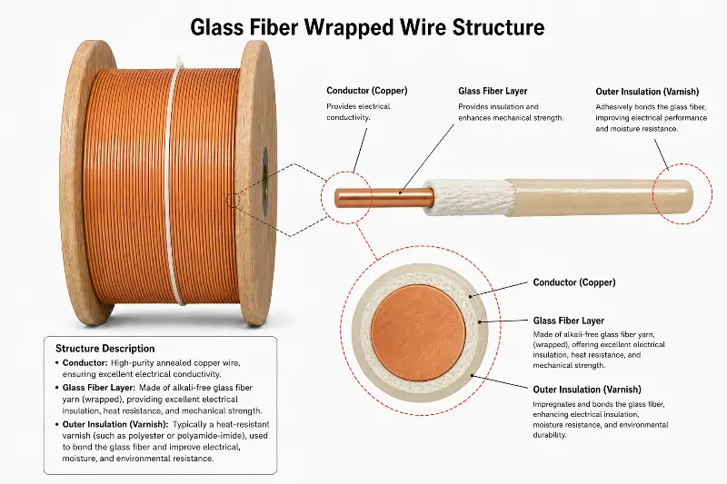
Fiberglass covered wire is a special type of winding wire with glass fiber filaments as the insulation layer. It consists of a conductor, an optional base insulation, a glass fiber covering layer, and an insulating varnish treatment layer. Fiberglass covered wire, along with enameled wire, paper-insulated wire, and film-insulated wire, is classified as one of the four major categories of winding insulated wires.
Regarding the conductor, glass-insulated wire typically uses electrolytic copper wire (ECW) or electrolytic aluminum wire. The copper conductor purity is ≥99.90% (ETP) or ≥99.97% (OFC), and the aluminum conductor purity is ≥99.5%. Conductor shapes include round wire (diameter 0.50-5.00mm) and rectangular/flat wire (thickness 1.00-8.00mm, width 3.00-25.00mm). Rectangular wire is used in high-current transformers and large generators.
Regarding the underlying film insulation, modern glass fiber wires typically add a layer of film insulation (enamel coating) beneath the glass fiber covering layer, forming a composite insulation structure of “enamel coating + glass fiber” or “film + glass fiber”. The thermal class of the underlying film insulation must meet Class 130 (polyester enamel coating) or Class 180 (polyester imide enamel coating, polyimide film).
For the glass fiber capping layer, the glass fiber used is electrical-grade continuous-filament glass yarn, which has excellent heat resistance, mechanical strength, and chemical resistance. The diameter of the glass fiber is typically 5-13 μm, and the twist is adjusted according to the wire diameter and application. The glass fiber capping methods include single-layer and double-layer. Single-layer capping provides basic insulation, while double-layer capping provides enhanced insulation (for high-voltage and high-reliability applications).
Regarding the insulating varnish treatment layer, the glass fiber covering layer needs to be coated with insulating varnish and then dried and cured to form a tough outer surface. Commonly used insulating varnishes include polyester resin (Polyester Varnish, F grade, 155°C), modified polyester resin (Modified Polyester Varnish, F/H grade, 155-180°C), silicone resin (Silicone Varnish, H/C grade, 180-220°C), and polyester imide resin (Polyesterimide Varnish, H grade, 180°C). The curing temperature, time, and number of layers of the insulating varnish determine the final thermal class and mechanical strength of the glass fiber-wrapped wire.
NEMA MW 1000-2018 standard specifies the core specifications for glass fiber insulated wire. MW 41-C specifies Class 155 glass fiber insulated round copper wire (bare wire or film insulation), with a single layer of glass fiber overlay and polyester insulating varnish treatment. MW 42-C specifies Class 180 glass fiber insulated round copper wire (bare wire or film insulation), with a double layer of glass fiber overlay and modified insulating varnish treatment. MW 47-C specifies Class 200 polyester fiberglass insulated round copper wire (bare wire or film insulation), with a single/double layer overlay and modified silicone insulating varnish treatment. IEC 60317-48 corresponds to MW 41-C standard. IEC 60317-0-8 specifies the technical requirements for polyester fiberglass insulated rectangular copper wire (flat wire).
Advantages of Fiberglass Covered Wire Over Enameled Wire
Glass-coated wire and enameled wire each have their advantages in renewable energy applications, but glass-coated wire has significant advantages in several key dimensions.
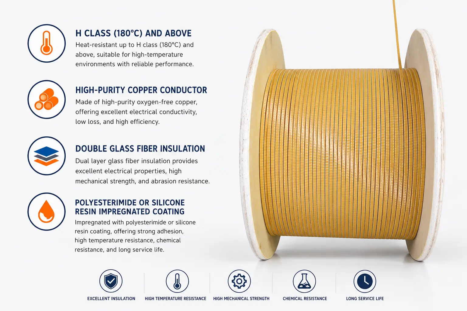
In terms of temperature resistance, glass fiber-insulated wire meets multiple insulation classes (Class 155/180/200/220), far exceeding the Class 130/155/180/200/220 of enameled wire. NEMA MW 47-C specifies Class 200 glass fiber-insulated wire that can withstand long-term operating temperatures of 200°C, making it the preferred choice for demanding applications such as offshore wind power transformers, energy storage converters, and high-temperature motors. While glass fiber itself can withstand temperatures above 550°C, the thermal class of the insulating varnish determines the overall temperature resistance of the glass fiber-insulated wire.
In terms of mechanical strength, glass fiber-insulated wire is significantly superior to enameled wire. The tensile strength of glass fiber can reach 2000-3500 MPa, which is 50-100 times that of enameled coating (20-50 MPa). Glass fiber-insulated wire is less prone to damage during winding, embedding, shaping, impregnation, and assembly processes, and can withstand greater tensile, bending, and abrasion stresses. Its mechanical strength advantage is particularly prominent in the winding manufacturing of large transformers (capacity ≥ 5 MVA) and large wind turbines (capacity ≥ 5 MW).
In terms of chemical resistance, glass fiber exhibits excellent resistance to most chemical media (acids, alkalis, salts, oils, and organic solvents). Glass fiber-insulated wire maintains insulation integrity in the high salt spray environment of offshore wind power, the acid rain environment of photovoltaics, the coolant environment of energy storage, and the corrosive gas environment of biomass. The enamel coating of enameled wire may swell, soften, and crack under long-term immersion in chemical media, leading to insulation failure.
In terms of heat dissipation performance, the glass fiber layer of the glass-insulated wire has a porous structure, which, when combined with the insulating varnish treatment, forms microchannels, facilitating the dissipation of heat from the inside of the winding to the outside. In high-power-density transformers and reactors, the heat dissipation performance of glass-insulated wire is superior to that of solid enamel-coated enameled wire, reducing temperature rise by 5-15%.
In terms of dimensional accuracy, rectangular glass fiber insulated wire (such as IEC 60317-0-8 polyester glass fiber enameled rectangular copper wire) has high dimensional accuracy, uniform insulation thickness, and a slot fill factor of 75-85%. The slot fill factor of enameled rectangular wire is usually 70-80%, while that of glass fiber insulated rectangular wire is even higher, which can effectively utilize the winding space.
In terms of corona resistance, glass fiber exhibits excellent corona resistance and is less prone to partial discharge under high-voltage electric fields. Glass fiber-wrapped wires are used in high-voltage transformers, high-voltage reactors, and high-voltage motors, where they can withstand higher voltage stresses.
Applications in Wind Power Generation
Wind power is a core area of renewable energy, and glass fiber-insulated wire is used in many key equipment of wind turbines, such as generators, transformers, reactors, and tower cables.
In the field of wind turbines, modern large-scale wind turbines (capacity 3-18 MW) mainly use double-fed induction generators (DFIGs) and permanent magnet synchronous generators (PMSGs). The stator and rotor windings of DFIGs, and the stator windings of PMSGs, typically use rectangular or circular glass-insulated wire (Class 180/200). Offshore wind turbines have large single-unit capacities (8-18 MW) and high voltage levels (≥690V AC), requiring stringent insulation levels, mechanical strength, and salt spray resistance for their generator windings. This makes glass-insulated wire (Class 200) a core application scenario.
In the wind power transformer sector, pad-mounted substations and step-up transformers in wind farms boost the turbine’s output voltage (690V AC) to medium voltage (35kV AC) or high voltage (110kV/220kV AC) for grid connection. Wind turbine transformer windings typically use rectangular glass-insulated wire (Class 155/180). The large cross-section of the rectangular wire (2-6mm thickness, 5-15mm width) accommodates the design requirements of high currents (100-3000A). Offshore wind turbine transformers have high requirements for tolerance to salt spray, temperature cycling (-25°C to +50°C), and vibration (5-50Hz), making H/C class insulation of the glass-insulated wire a core technology.
In wind power reactors, wind farms utilize a large number of reactors in their static var compensators (SVCs) and filters. The reactor windings typically use rectangular or circular glass-insulated wire (Class 155/180), with the large cross-section of the rectangular wire suitable for high current (100-2000A) designs. Reactors have high requirements for insulation thermal class, mechanical strength, and heat dissipation performance; glass-insulated wire is the preferred option.
Regarding tower cables, the internal wiring of the wind turbine tower (Yaw Motor Cable, Pitch Motor Cable, Control Cable) uses special cables. The conductors of the cables are usually insulated with glass fiber or mica tape to withstand the high temperature (up to 60-80°C in summer) and vibration environment inside the tower.
Regarding the special requirements for offshore wind power, offshore wind farms face extreme environments such as high salt spray (Cl⁻ concentration ≥ 5 mg/m³), high humidity (relative humidity ≥ 95%), temperature cycling (-20°C to +45°C), strong wind vibration, and typhoon impact. Offshore wind turbine generators, transformers, and reactors must use Class 200 glass fiber-insulated wire (treated with silicone resin) and pass the IEC 60068-2-52 salt spray test (≥ 56 days) and the IEC 60068-2-14 temperature cycling test (≥ 100 cycles).
Applications in Solar PV and Energy Storage
Photovoltaic power generation (Solar PV) and energy storage are another core area of renewable energy. Glass fiber-insulated wire is used in key equipment such as photovoltaic inverters, step-up transformers, energy storage converters, and battery management systems.
In the photovoltaic (PV) inverter sector, the inverter converts the direct current (DC 600-1500V) from the PV module into alternating current (AC 380V/480V/690V). Core components include a boost inductor, a filter inductor, an LF transformer, and an output reactor. The windings of the boost and filter inductors typically use rectangular or circular glass fiber insulated wire (Class 155/180). The large cross-section of the rectangular wire is suitable for high current (100-500A) designs. PV inverters can operate at temperatures ranging from 70-85°C and frequencies from 16-50 kHz. High requirements are placed on the insulation’s temperature resistance, heat dissipation, and high-frequency performance; glass fiber insulated wire is the preferred solution.
In the area of photovoltaic (PV) voltage booster transformers, the pad-mounted step-up transformer in a PV power plant boosts the inverter’s output voltage (AC 380V/480V/690V) to medium voltage (AC 10kV/35kV) for grid connection. The windings of PV voltage booster transformers typically use rectangular glass-insulated wire (Class 155/180), whose large cross-section is suitable for high-current designs. PV power plants are often deployed in harsh environments such as deserts, Gobi, and plateaus, requiring transformers with high resistance to temperature, UV radiation, and dust; glass-insulated wire offers significant advantages in environmental resistance.
In terms of power storage converters (PCS), the PCS of a battery energy storage system converts the battery’s direct current (DC 600-1500V) into alternating current (AC 380V/480V). Core components include a DC/DC converter, a DC/AC inverter, a power frequency transformer, and a filter inductor. The windings of the energy storage converter typically use rectangular or circular glass fiber insulated wire (Class 155/180) to accommodate high current, high frequency, and high efficiency designs. Energy storage converters have high requirements for insulation temperature resistance, heat dissipation, and reliability; glass fiber insulated wire is the preferred solution.
In the field of energy storage transformers, the boost transformers of large battery energy storage systems raise the PCS output voltage (AC 380V/480V) to medium voltage (AC 10kV/35kV) and connect it to the grid. The windings of energy storage transformers typically use rectangular glass fiber wrapped wire (Class 155/180) to accommodate high current designs. Energy storage systems are typically deployed in industrial plants, commercial buildings, and residential settings, placing high demands on the safety, reliability, and low noise of the transformers.
Regarding the BMS and battery pack, components such as the current sensor, isolation transformer, and common mode inductor of the battery management system (BMS) use round or rectangular glass fiber wrapped wire (Class 130/155) to meet the design requirements of miniaturization and high reliability.
Applications in Hydrogen Energy and EV Charging
Hydrogen energy and electric vehicle (EV) charging are emerging fields of renewable energy applications. Glass fiber-wrapped wire is used in key equipment such as electrolyzer power supplies, fuel cell stacks, charging stations, and OBCs.
In hydrogen production via water electrolysis, the power supply for the electrolyzer (PEM Electrolyzer Power Supply or Alkaline Electrolyzer Power Supply) converts alternating current (AC 380V/480V) to direct current (DC 100-500V) to drive the electrolyzer and produce hydrogen. The core components of the electrolyzer power supply include a rectifier transformer, a filter inductor, and a DC reactor. The rectifier transformer windings typically use rectangular or circular glass fiber wrapped wire (Class 155/180) to accommodate high current designs. The operating environment of the electrolyzer is usually high humidity (relative humidity ≥80%) and low vibration, requiring high moisture resistance from the transformer.
In terms of fuel cells, the fuel cell stack of a fuel cell vehicle (FCV) outputs direct current (DC 200-650V), which is then boosted to high voltage (DC 400-800V) via a DC/DC boost converter to power the drive motor. The fuel cell’s DC/DC converter employs a high-frequency transformer (switching frequency 50-100 kHz) and filter inductors, with windings using Litz wire or rectangular glass fiber wrapped wire (Class 180/200). Fuel cells can operate at temperatures ranging from 60-80°C, requiring high temperature resistance from the insulation.
In terms of charging stations, charging piles for new energy vehicles include AC charging stations and DC charging stations. The core components of a DC charging station include a rectifier transformer, a DC/DC converter, and a filter inductor. The rectifier transformer typically uses rectangular or circular glass fiber insulated wire (Class 155/180) to accommodate high-current designs. Charging stations are usually deployed outdoors, requiring high insulation performance in terms of temperature resistance, moisture resistance, UV resistance, and salt spray resistance; glass fiber insulated wire is the preferred solution.
In terms of on-board chargers (OBCs), the on-board charger (OBC) of new energy vehicles converts alternating current (AC 220V/380V) to direct current (DC 400-800V) to charge the power battery. The core components of the OBC include a power frequency isolation transformer, a resonant inductor, and a filter inductor. The windings typically use Litz wire or rectangular glass fiber wrapped wire (Class 180). Since the OBC is deployed inside the vehicle, it has high requirements for insulation temperature resistance (70-85°C), vibration resistance (5-2000Hz), and reliability.
In terms of DC/DC converters, those used in new energy vehicles convert high-voltage batteries (HV batteries, 400-800V) into low-voltage (12V/48V) power to supply the vehicle’s electrical system. The core components of a DC/DC converter include a high-frequency transformer, a filter inductor, and a resonant inductor. The windings typically use Litz wire or rectangular glass fiber wrapped wire (Class 180/200). DC/DC converters operate at high frequencies (50-200 kHz) and high temperatures (85-105°C), placing stringent requirements on the high-frequency resistance and high-temperature resistance of the insulation.
Applications in Biomass and Geothermal Power Generation
Biomass power generation and geothermal power generation are complementary areas of renewable energy, and glass fiber-insulated wire is used in key equipment such as biomass boilers and geothermal generators.
In biomass power generation, the capacity of biomass boilers and turbine generators is typically 5-50 MW, with operating temperatures of 400-540°C and pressures of 4-13 MPa. The stator and rotor windings of biomass turbine generators usually use rectangular or circular glass fiber wrapped wire (Class 180/200) to accommodate high current and high speed designs. The flue gas produced by burning biomass fuels (straw, sawdust, and waste-derived fuel RDF) contains corrosive substances (Cl⁻, SO₂, NOₓ), requiring high chemical resistance in the insulation; glass fiber wrapped wire is the preferred solution.
In geothermal power generation, geothermal turbine generators typically have capacities of 5-100 MW and operate at temperatures of 150-350°C. The stator and rotor windings of these generators usually use rectangular or circular glass fiber wrapped wire (Class 180/200/220) to accommodate high temperatures, high currents, and high speeds. Since the geothermal fluids used in geothermal power generation contain hydrogen sulfide (H₂S), carbon dioxide (CO₂), and chloride ions (Cl⁻), high chemical resistance is required for the insulation.
In waste-to-energy (WTE) power generation, the turbine generator capacity is typically 10-50 MW, with an operating temperature of 400-500°C. The flue gas from waste incineration contains hydrogen chloride (HCl), hydrogen fluoride (HF), and heavy metal vapors, requiring extremely high corrosion resistance from the insulation. The windings in WTE power plants typically use Class 200/220 glass fiber insulated wire (treated with silicone resin) and pass the IEC 60068-2-42 acid atmosphere test (≥56 days).
Breakdown Voltage and Insulation Reliability
The insulation reliability of glass-insulated wire is a core element for the safe operation of renewable energy equipment. The NEMA MW 1000-2018 and IEC 60317 series standards specify the breakdown voltage requirements for glass-insulated wire.
The breakdown voltage requirements for NEMA MW 41-C (Class 155 glass-insulated round copper wire) are as follows: Single-layer AWG 4/0-9.5 ≥ 170V, Single-layer AWG 10-23.5 ≥ 360V, Single-layer AWG 24-30 ≥ 225V; Double-layer AWG 4/0-9.5 ≥ 315V, Double-layer AWG 10-23.5 ≥ 540V, Double-layer AWG 24-30 ≥ 400V. For glass-insulated wire with a bottom film insulation layer, the breakdown voltage of the film insulation layer must be added on top of the glass-insulated breakdown voltage.
The breakdown voltage requirements for NEMA MW 47-C (Class 200 polyester fiberglass-coated round copper wire) are as follows: Single-layer AWG 4-9.5 ≥ 150V, Single-layer AWG 10-23.5 ≥ 360V, Single-layer AWG 24-30 ≥ 225V; Double-layer AWG 4-9.5 ≥ 270V, Double-layer AWG 10-23.5 ≥ 540V, Double-layer AWG 24-30 ≥ 400V.
The breakdown voltage requirements for IEC 60317-0-8 (polyester enameled rectangular copper wire) are as follows: single-layer bare conductor (PG1) ≥350V, double-layer bare conductor (PG2) ≥560V; Grade 1 single-layer bare conductor (PG1) ≥1350V, double-layer bare conductor (PG2) ≥1560V; Grade 2 single-layer bare conductor (PG1) ≥2350V, double-layer bare conductor (PG2) ≥2560V.
Regarding elongation requirements, NEMA MW 41-C specifies the minimum elongation for glass fiber wrapped round copper wire (with/without glass fiber): AWG 4/0-1/0 35%/35%, AWG 1-8 30%/30%, AWG 9-15 20%/30%, AWG 16-21 15%/25%, AWG 22-28 —/20%, AWG 29-30 —/15%. Insufficient elongation can lead to breakage of the glass fiber wrapping during winding, reducing yield.
For accelerated aging testing, the accelerated aging test of glass-inlaid wire is based on the thermal aging test method specified in IEC 60172 standard, and the lifespan is calculated using the Arrhenius equation. The long-term operating temperature of Class 155/180/200/220 glass-inlaid wire corresponds to a lifespan of 20,000 hours. Glass-inlaid wires for demanding applications such as offshore wind power and waste incineration power generation must pass the IEC 60068-2-14 temperature cycling test, the IEC 60068-2-52 salt spray test, and the IEC 60068-2-42 acidic atmosphere test.
Key Manufacturing Processes
The manufacturing process of glass fiber wrapped wire includes conductor pretreatment, bottom insulation coating (optional), glass fiber braiding/winding, insulating varnish impregnation, drying and curing, and winding and packaging.
For conductor pretreatment, glass-insulated wire conductors (round copper wire, rectangular copper wire, aluminum wire) need to undergo annealing to improve flexibility and elongation. The annealing temperature is usually 400-600°C, and the conductor elongation can reach 25-35% after annealing.
Regarding the optional underlayer insulation coating, modern glass fiber-insulated wires (MW 41-C, MW 47-C) typically have a thin film insulation layer (polyester enamel coating, polyester imide enamel coating) applied before the glass fiber coverage, forming an “enamel coating + glass fiber” composite insulation. The underlayer enamel coating is applied using an enameling machine and then cured in an oven.
In glass fiber braiding/winding, glass fibers are applied to the conductor surface using either a braiding machine or a winding machine. Braiding machines are suitable for multi-spindle braiding of round conductors, while winding machines are suitable for flat winding of rectangular conductors. The coverage density, tension, and uniformity of the glass fibers are key quality control points in manufacturing. NEMA MW 41-C requires that the glass fibers be applied to the conductor surface “firmly, closely, evenly, and continuously.”
For insulating varnish impregnation, conductors covered with glass fiber need to be impregnated with insulating varnish and then cured in an oven. Commonly used insulating varnishes include polyester resin, modified polyester resin, silicone resin, and polyester imide resin. The viscosity, solids content, curing temperature, and curing time of the insulating varnish determine the final insulation performance. Class 155 typically uses polyester resin, Class 180 uses modified polyester resin or polyester imide resin, and Class 200/220 uses modified silicone resin or silicone resin compounds.
For drying and curing, the insulating varnish is dried and cured in a vertical or horizontal oven. The curing temperature is typically 200-300°C (polyester varnish) or 250-350°C (silicone varnish), and the curing time is 30-120 seconds (multiple cycles). The curing process requires precise control of the temperature gradient and tension to avoid cracking of the enamel coating or damage to the glass fibers.
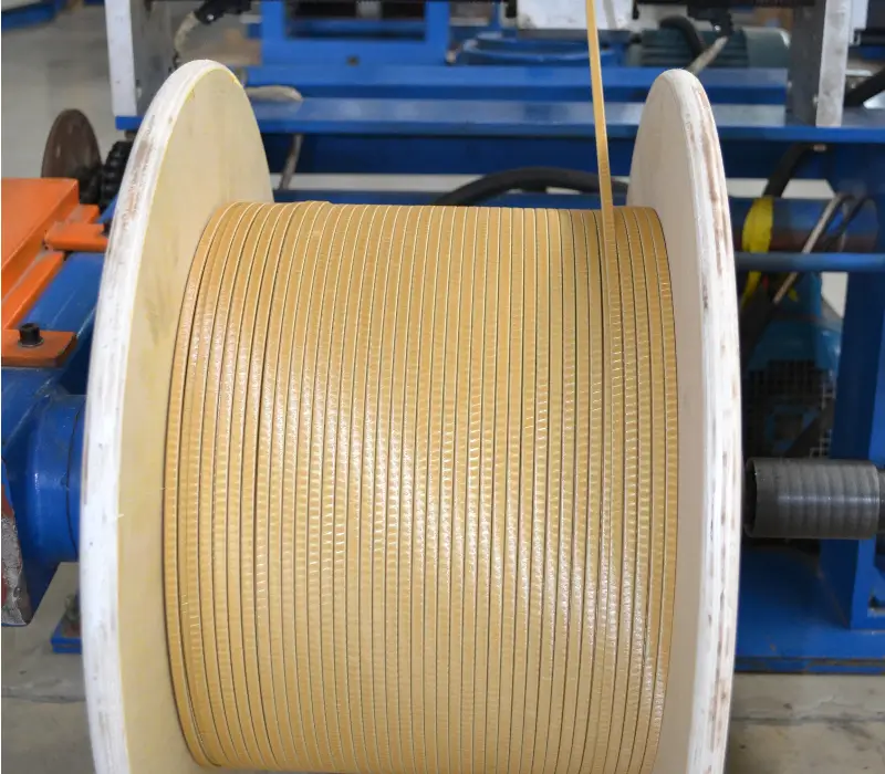
For winding and packaging, the finished glass fiber wrapped wire is wound onto standard spools (PT4-PT200 series) using a winding machine, with each spool weighing 4-200 kg. Tension and wire arrangement must be controlled during the winding process to avoid damage to the wire.
Selection Decision Recommendations
The selection of glass fiber-insulated wire in the renewable energy field should be based on a comprehensive judgment of application scenario, insulation class, mechanical strength, reliability requirements, and cost.
Recommended initial solution: For general onshore wind power (≤3 MW), distributed photovoltaic (≤1 MW), and residential energy storage (≤100 kWh), choose Class 155 glass fiber wrapped round copper wire (MW 41-C, single-layer coverage), suitable for normal environments (-20°C to +50°C, salt spray ≤2 mg/m³). Advantages: moderate cost, reliable insulation, and easy to process.
Recommended intermediate-level solutions: For onshore wind power (3-8 MW), centralized photovoltaic (1-100 MW), and industrial/commercial energy storage (100 kWh-10 MWh), choose Class 180 glass-insulated rectangular copper wire (IEC 60317-0-8, Class 2 enameled coating), suitable for harsh environments (-30°C to +60°C, salt spray ≤4 mg/m³). Advantages: higher temperature resistance, better mechanical strength, and better reliability.
Recommended Advanced Solution: For offshore wind power (≥8 MW), large-scale centralized photovoltaic (≥100 MW), large-scale energy storage (≥10 MWh), and charging stations, select Class 200 polyester fiberglass-coated round copper wire (MW 47-C, single/double layer coverage) or rectangular wire for the transformer, suitable for extreme environments such as offshore, desert, and plateau (-40°C to +70°C, salt spray ≥5 mg/m³). Advantages: Highest temperature resistance, best chemical resistance, and best reliability.
Recommended solution for extreme environments: For extreme environments such as waste-to-energy incineration, geothermal power generation, desert photovoltaic, and deep-sea wind power, choose Class 200/220 silicone resin treated glass fiber wrapped wire, suitable for highly corrosive, high-temperature, and high-humidity environments. Advantages: Best corrosion resistance, highest temperature resistance, and longest lifespan.
Regarding unrecommended options: Class 130 enameled wire (such as polyvinyl acetal enameled wire) is not recommended for use in renewable energy fields due to its low thermal class. Ordinary polyester enameled wire (Class 155) is not recommended for use in large transformers and large generators due to its limited mechanical strength.
Future Development Trends
The rapid growth of renewable energy is driving continuous innovation and market expansion in glass fiber wrapping technology.
Regarding the growth of offshore wind power, the global cumulative installed capacity is expected to increase from 75 GW in 2024 to 380 GW in 2030, leading to a significant increase in demand for Class 200/220 glass fiber-insulated wire. The requirements for salt spray resistance (≥56 days IEC 60068-2-52 test), temperature cycling resistance (≥100 cycles), and vibration resistance (≥10 years of life) in offshore wind power are driving the upgrading of glass fiber-insulated wire technology.
Regarding the explosive growth of energy storage, global battery energy storage system installations are projected to increase from 200 GWh in 2024 to 1500 GWh in 2030, leading to a rapid increase in demand for glass fiber-insulated wire. The increasing frequency (switching frequency 50-100 kHz) and power density (≥100 kW/L) of energy storage converters (PCS) are driving continuous improvements in the insulation grade, heat dissipation performance, and mechanical strength of glass fiber-insulated wire.
In emerging applications of hydrogen energy, the installed capacity for hydrogen production through water electrolysis is expected to grow rapidly, leading to increased demand for Class 180/200 glass-insulated wire for PEM electrolyzer power supplies and alkaline electrolyzer power supplies. The rapid development of the hydrogen energy industry chain is opening up new application scenarios for glass-insulated wire.
Regarding the growth of new energy vehicle charging, the global installed capacity of new energy vehicle charging stations is expected to increase from 50 million units in 2024 to 200 million units in 2030, leading to a significant increase in demand for glass fiber-insulated wire. The demand for Class 180/200 glass fiber-insulated wire is rapidly increasing for rectifiers in DC charging stations (≥120 kW) and DC/DC converters in supercharging piles (≥350 kW).
In terms of technological upgrade directions, the technological upgrade directions for glass fiber-insulated wire include: thermal class improvement (Class 220/240/260), cross-section increase of rectangular wire (thickness ≥10mm, width ≥30mm), environmental protection of insulating varnish (water-based varnish, low VOC varnish), intelligent manufacturing (online detection, AI quality control), and recycling (copper conductor recycling, glass fiber recycling).
In terms of market size, the global glass fiber insulated wire market is projected to grow from US$2.5 billion in 2024 to US$6.5 billion in 2030, with a compound annual growth rate (CAGR) of approximately 17%. China is the world’s largest producer and consumer of glass fiber insulated wire, accounting for 35-40% of the global market share.
Conclusion
The rapid growth of renewable energy has opened up vast application spaces and market opportunities for glass fiber-insulated wire. With its advantages such as high temperature resistance (H/C grade), high mechanical strength, excellent chemical resistance, good heat dissipation, and high dimensional accuracy, glass fiber-insulated wire plays a crucial role in various fields including wind power generation, photovoltaic power generation, energy storage, hydrogen energy, new energy vehicle charging, biomass power generation, and geothermal power generation.
The selection of glass fiber insulated wire should comprehensively consider the application scenario, insulation class, mechanical strength, reliability requirements, and cost. NEMA MW 41-C (Class 155), NEMA MW 42-C (Class 180), and NEMA MW 47-C (Class 200) are the core international standards for glass fiber insulated wire. IEC 60317-48 (corresponding to MW 41-C) and IEC 60317-0-8 (polyester-coated rectangular copper wire) are the corresponding standards in the IEC system.
With the explosive growth of offshore wind power, battery energy storage, hydrogen energy, and new energy vehicle charging, the market demand for Class 200/220 glass fiber-insulated wire will continue to grow rapidly. Engineers should fully leverage the advantages of glass fiber-insulated wire—high temperature resistance, high strength, and high reliability—while rigorously evaluating its long-term reliability under salt spray, temperature cycling, vibration, and chemical corrosion environments. Composite insulation technology (enamel coating + glass fiber + silicone resin), ultra-large cross-section rectangular wire technology, environmentally friendly insulating varnish technology, and intelligent manufacturing technology will become the core directions for the future development of glass fiber-insulated wire technology.