


High-power transformers (High Power Transformer) typically refer to power transformers, distribution transformers, traction transformers, rectifier transformers, and special-purpose power transformers with a rated capacity ≥1 MVA. Their windings operate continuously under a triply coupled environment of high voltage (10–500 kV), high current (hundreds to thousands of amperes), and elevated temperature (hot-spot temperature up to 150–200°C), imposing stringent requirements on winding conductors:
**Electrical Performance**: High dielectric strength to withstand turn-to-turn, phase-to-phase, and phase-to-ground voltage stresses; high partial discharge inception voltage (PDIV) to tolerate potential voids remaining after vacuum pressure impregnation (VPI); low dielectric loss (tan δ) to minimize operational energy losses.
**Mechanical Performance**: Resistance to electromagnetic short-circuit forces (typical short-circuit currents of 50–100 kA generate mechanical forces of 10–20 kN); resistance to vibration (transformer body vibration frequency range: 5–200 Hz); resistance to thermal expansion (winding thermal cycling).
**Thermal Performance**: High thermal class rating (F: 155°C, H: 180°C, N: 200°C, R: 220°C); low coefficient of thermal expansion to ensure dimensional stability of windings; good thermal conductivity to reduce temperature rise.
**Chemical Performance**: Resistance to transformer oils (mineral oil, synthetic esters); resistance to impregnating varnishes (polyester, epoxy, silicone, polyimide); resistance to moisture and industrial atmospheres.
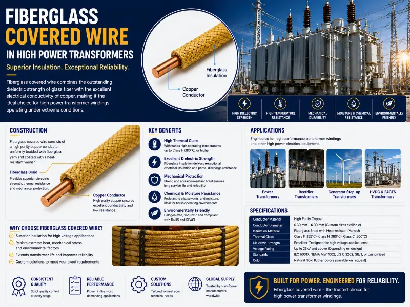
Single-layer enameled wires (e.g., PEI, PAI, PI) exhibit clear limitations in this application: enamel film thickness is constrained by mechanical and thermal dissipation requirements (Grade 2 typically 30–60 μm); dielectric strength ranges from 40–200 kV/mm but mechanical damage resistance and oil-environment compatibility are insufficient. Fiberglass covered wire (Fiberglass Covered Wire), employing a multi-layer composite structure—comprising conductor + optional base enamel layer + braided glass fiber layer + impregnated insulating varnish—simultaneously fulfills all four categories of requirements and is thus one of the core materials for high-power transformer windings.
Insulation Structure Analysis of Fiberglass-Covered Magnet Wire
Typical 5-layer composite structure of fiberglass-covered magnet wire (from innermost to outermost):
**Layer 1: Conductor**
- Material: Electrolytic-tough-pitch (ETP, C11000) round copper wire; 1350 alloy round aluminum wire; rectangular copper or aluminum conductors
- Dimensions: Round wire Ø0.5–7.0 mm; Rectangular wire thickness 1.0–10.0 mm × width 3.0–35.0 mm
- Standards: ASTM B49, B170 (copper rod); ASTM B233, B566 (aluminum rod); ASTM B609 (drawing and annealing)
**Layer 2: Base Enamel Film (Optional)**
- Types: PEW (polyester, 130°C), PEI (polyester-imide, 155°C), PAI (polyamide-imide, 180–200°C), PI (polyimide, 200–240°C)
- Function: Smoothing conductor surface irregularities (e.g., burrs), enhancing turn-to-turn insulation integrity, contributing primary insulation thickness
- Standards: IEC 60317 series, NEMA MW 1000
**Layer 3: Glass Fiber Braided Layer**
- Material: E-glass (alkali-free) fiber yarn; key specification: tex 6.6–110
- Construction: Single-layer, double-layer, or multi-layer helical braiding; braiding angle adjusted per wire diameter
- Overlap rate: 50–80%
- Key parameters: Braiding speed 200–500 rpm; Braiding tension 1.0–3.0 N
- Standards: IEC 60817, NEMA MW 1000 Annex
**Layer 4: Insulating Varnish Impregnation**
- Types: Oil-based varnish (B/F class, 130–155°C); Polyester varnish (F class, 155°C); Modified polyester + silicone (H class, 180°C); Pure silicone (H class, 180°C); High-temperature-resistant organic varnish (H class, 180°C); Polyimide varnish (C class, 220°C)
- Process: Atmospheric-pressure impregnation; Vacuum Pressure Impregnation (VPI: vacuum ≤100 Pa, pressure 0.2–0.6 MPa); Continuous drip coating or roll coating
- Viscosity control: 250–450 mPa·s at 25°C
- Standards: IEC 60851-5, ASTM D3144
**Layer 5: Outer Protective Coating (Optional)**
- Standard enamel film / wax coating / PTFE surface coating / laser marking
Glass Fiber Types and Electrical Performance Comparison
Glass fiber is classified into four types based on chemical composition:
| Glass Fiber Type | SiO₂ Content | Key Characteristics | Typical Applications |
|---|---|---|---|
| E-glass (alkali-free glass fiber) | 52–62% | Excellent overall performance, low cost, superior electrical properties | Dominant type for fiberglass-covered wire (accounts for >95% of market) |
| S-glass (high-strength glass fiber) | ~65% | Tensile strength 30–40% higher than E-glass; high-temperature resistance | High-strength applications (aerospace, traction) |
| D-glass (dielectric glass fiber) | 70–75% | Low dielectric constant (3.8 vs. 6.3 for E-glass); low dielectric loss | Specialized high-frequency, high-voltage applications |
| Basalt fiber | 50–60% | Higher temperature resistance (up to 900°C); acid/alkali resistance | Specialized high-temperature applications |
Key electrical and mechanical parameters of fiberglass-covered wire:
| Parameter | Fiberglass-Covered Wire (Typical) | Enamelled Wire (Typical) |
|---|---|---|
| Dielectric Strength | 10–20 kV/mm (fiberglass layer) | 30–200 kV/mm (enamel coating) |
| Tensile Strength | 2000–3500 MPa (fiberglass) | 100–200 MPa (enamel coating) |
| Elastic Modulus | 70–80 GPa (fiberglass) | 3–5 GPa (enamel coating) |
| Softening Point | 800–1000°C (fiberglass) | 200–400°C (enamel softening/decomposition) |
| Coefficient of Thermal Expansion | 5×10⁻⁶/°C (fiberglass) | 30–80×10⁻⁶/°C (enamel coating) |
| Oil Resistance | Excellent (no swelling in mineral oil) | Moderate (excellent for PAI/PI; poor for PEW/PEI) |
| Breakdown Voltage (Round Wire, Single Layer) | ≥360 V (AWG 10–23.5, MW 41-C) | ≥1.4 kV (Grade 1 twisted method) |
Although the dielectric strength of fiberglass appears lower than that of enamel coatings (10–20 vs. 30–200 kV/mm), fiberglass-covered wire achieves higher overall breakdown voltage through a **multi-layer structure + insulating varnish filling voids**. Per NEMA MW 41-C (Class 155), single-layer fiberglass-covered round wire exhibits breakdown voltage ≥360 V (AWG 10–23.5); double-layer ≥540 V. Identical specifications apply to NEMA MW 47-C (Class 200). Per IEC 60317-0-8, breakdown voltage for rectangular fiberglass-covered wire is ≥1350 V for Grade 1 (single layer), with eight thickness-based classifications (maximum 2560 V).
Types of High-Power Transformers and Fiberglass-Covered Wire Configurations
Distribution Transformers (≤2.5 MVA, ≤35 kV)
**Winding Structure**: Low-voltage side — rectangular/flat wire windings (tens to hundreds of turns); high-voltage side — multi-layer round/flat wire windings.
**Fiberglass-Covered Wire Configuration**:
- Low-voltage side (≤1 kV): Rectangular copper wire + single-layer fiberglass + F/H-class insulating varnish impregnation
- High-voltage side (10–35 kV): Round copper wire + polyimide (PI) film base coat + double-layer fiberglass + H-class insulating varnish + VPI process
- Applicable Specifications: NEMA MW 41-C / 45-C, IEC 60317-0-8
Dry-Type Transformers (H/C-Class Insulation)
**Winding Structure**: Open windings, cast-resin windings (epoxy), vacuum pressure impregnated (VPI) windings.
**Fiberglass-Covered Wire Configuration**:
- Open-type: Round/rectangular copper wire + single/double-layer fiberglass + H-class insulating varnish VPI
- Cast-resin type: Fiberglass-covered wire + epoxy resin vacuum casting
- Applicable Specifications: NEMA MW 44-C / 50-C (Class 200), MW 51-C / 52-C (Class 220)
- Applicable Thermal Classes: H (180°C) / N (200°C) / R (220°C)
- Standards: UL 1446 (insulation system certification, mandatory), IEC 60076-11 (dry-type transformers)
Oil-Immersed Transformers (A-Class + Mineral Oil)
**Winding Structure**: Multi-layer round copper wire/enamel wire windings; interlayer insulation using cable paper/telephone paper; overall immersion in mineral oil.
**Fiberglass-Covered Wire Configuration**:
- Fiberglass-covered wire is not the preferred choice (paper-wrapped wire is more economical for oil-immersed applications)
- Special applications: High-temperature zones of oil-immersed traction transformers; high-overload distribution transformers
- Alternative solution: Paper-wrapped copper wire + mineral oil + oil-impregnating varnish
- Long-term contact between fiberglass layer and transformer oil may cause compatibility issues; oil-resistant impregnating varnish must be selected
Traction Transformers (High-Speed Rail 25 kV)
**Winding Structure**: 25 kV high-voltage winding, low-voltage winding at several kV, resonant reactor winding.
**Fiberglass-Covered Wire Configuration**:
- High-voltage side: PI film + double-layer fiberglass + polyimide varnish impregnation (N/C-class)
- Low-voltage side: H-class fiberglass-covered rectangular copper wire
- Applicable Specifications: NEMA MW 50-C / 51-C, IEC 60317-46 / 47
- Key Technical Requirements: Fire resistance and flame retardancy (EN 45545-2 HL3), vibration resistance (IEC 61373), oil resistance (mineral oil or synthetic ester)
Rectifier Transformers (Electrolysis, Electrochemical)
**Winding Structure**: Primary side — 10–110 kV; secondary side — high-current, low-voltage (hundreds to thousands of volts, thousands of amperes).
**Fiberglass-Covered Wire Configuration**:
- Secondary side: Rectangular copper wire + multi-layer fiberglass + H/C-class insulating varnish VPI
- Applicable Specifications: MW 50-C / 51-C / 52-C
- Key Technical Requirements: High-current thermal management (rectangular wire + fiberglass enhances heat dissipation), harmonic tolerance (rectifier harmonics induce additional temperature rise)
Wind Power / Photovoltaic Pad-Mounted Transformers
**Winding Structure**: Low-voltage side (690 V–1500 V), high-voltage side (10–35 kV).
**Fiberglass-Covered Wire Configuration**:
- Wind power: H-class fiberglass-covered round/rectangular copper wire + VPI
- Photovoltaic: F/H-class fiberglass-covered round copper wire + dry-type insulation
- Applicable Specifications: NEMA MW 41-C / 44-C, IEC 60317-0-8
- Key Technical Requirements: Vibration resistance (IEC 61400-21), temperature cycling endurance (−40 °C to +155 °C outdoor)
Temperature Class System for Fiberglass-Covered Magnet Wire
The temperature class of fiberglass-covered magnet wire per IEC 60085 / NEMA MW 1000 depends on the **impregnating varnish system**, not the fiberglass itself (fiberglass softening point: 800–1000°C, far exceeding that of any organic varnish):
| Temperature Class | Maximum Temperature | Impregnating Varnish Type | Typical Applications |
|---|---|---|---|
| F | 155°C | Oil-based varnish, polyester varnish | Dry-type distribution transformers, mining transformers |
| H | 180°C | Modified polyester + silicone, pure silicone | Dry-type transformers, high-voltage motors, traction motors |
| N | 200°C | Special silicone, polyester-imide modified | Traction transformers, wind turbine generators |
| R | 220°C | Modified silicone, polyimide-modified | High-speed rail traction transformers, aerospace transformers |
| 250 | 250°C | Polyimide varnish, ceramic coating | Aerospace, special-purpose power supplies |
The temperature class of the wire is typically matched to the underlying enamel film: PAI enamel film is commonly used for H-class fiberglass-covered wire; PI enamel film is commonly used for N- and R-class fiberglass-covered wire. Mismatching creates a “weakest-link effect”—e.g., a PI enamel film (200°C+) paired with F-class impregnating varnish (155°C) reduces the overall temperature class to Class F.
VPI (Vacuum Pressure Impregnation) Process Detailed Explanation
VPI is the core process for fiberglass-covered wire windings in high-power transformers, determining the integrity and service life of the winding insulation system.
VPI Process Flow
**Step 1: Conductor Pre-treatment**
Round copper or aluminum conductors undergo mechanical scraping or chemical micro-etching to remove oxides, oils, and burrs. Copper conductors may optionally receive surface passivation or roughening to enhance enamel adhesion.
**Step 2: Fiberglass Tape Winding**
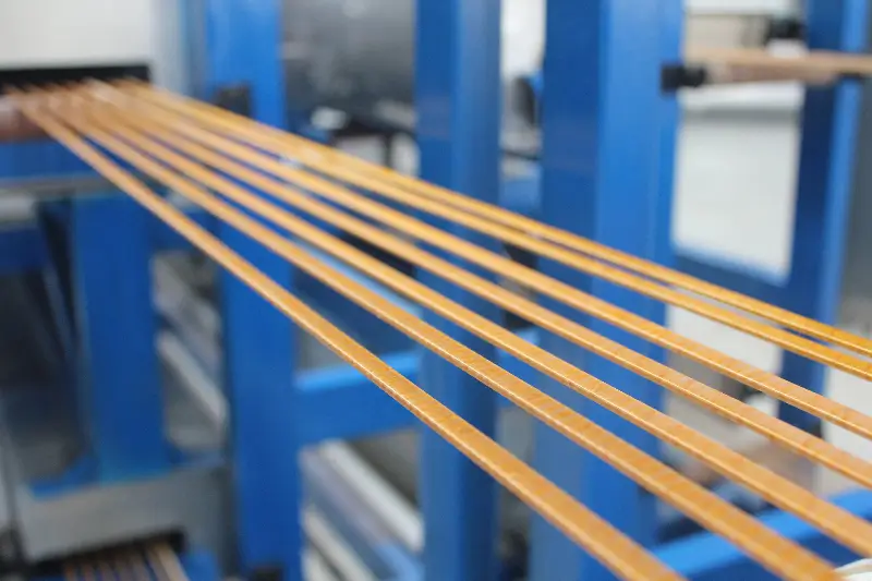
E-glass fiber yarn is helically wound onto the conductor with an overlap ratio of 50–80%. After single-layer winding, the conductor proceeds to pre-curing or directly to impregnation; for double-layer winding, an intermediate cure may be applied between layers.
**Step 3: Vacuum Pressure Impregnation**
- Vacuum stage: Vacuum level ≤100 Pa, to evacuate air from within the fiberglass layer
- Pressure impregnation: Impregnating varnish is forced into the fiberglass interstices under pressure of 0.2–0.6 MPa
- Viscosity control: 250–450 mPa·s at 25°C
- Impregnation time: 20–60 s for continuous production; 30–60 min for batch-type VPI
**Step 4: Drying and Curing**
| Impregnating Varnish Class | Drying Temperature | Drying Time |
|---|---|---|
| Class F | 130–150°C | 4–6 h |
| Class H | 180–200°C | 4–8 h |
| Class C | 220–240°C | 6–10 h |
Temperature uniformity must be maintained within ±5°C to prevent blistering, cracking, or localized under-cure.
Key VPI Process Quality Parameters
- **Vacuum level**: ≤100 Pa (ensures complete air gap removal)
- **Pressure**: 0.2–0.6 MPa (ensures varnish penetration)
- **Viscosity**: 250–450 mPa·s (balances flowability and penetrability)
- **Temperature uniformity**: ±5°C (prevents defects)
- **Residual volatile content after drying**: <1% (prevents blistering during operation)
Process Economics Comparison: Fiberglass-Covered Wire vs. Enamelled Wire vs. Paper-Insulated Wire
| Parameter | Fiberglass-Covered Wire | Enamelled Wire | Paper-Insulated Wire |
|---|---|---|---|
| Unit Cost | Medium (2–3× enamelled wire) | Low | Lowest |
| Insulation Thickness | Medium (0.2–0.6 mm) | Thin (30–60 μm) | Thick (1–5 mm, multi-layer) |
| Dielectric Breakdown Voltage | Medium (500–2500 V) | Medium–High (≥2.8 kV, Grade 2) | High (5–50 kV, multi-layer) |
| Mechanical Damage Resistance | Excellent (E-glass tensile strength >2000 MPa) | Poor (enamel film easily scratched) | Medium (paper prone to tearing) |
| Thermal Resistance | Full coverage of Class F/C/R | Limited by single enamel film (Classes F/H/N/R) | Class A (105°C, oil-immersed) |
| Oil Resistance | Excellent (no swelling in mineral oil) | Medium (PI/PAI excellent; PEW/PEI poor) | Poor (absorbs oil and swells) |
| Typical Applications | Dry-type transformers, traction systems, wind power generators | General-purpose motors and transformers | Oil-immersed transformers |
| Process Complexity | High (multi-step + VPI) | Medium (enamel coating + baking) | Low (paper wrapping + oil impregnation) |
**Economic Conclusion**: Fiberglass-covered wire delivers the highest overall cost-performance ratio in high-power dry-type transformers, traction transformers, wind power applications, and high-speed rail systems operating under elevated temperatures; paper-insulated wire remains dominant for oil-immersed distribution transformers; enamelled wire retains its advantage in low-to-medium voltage and small-capacity applications.
Key Testing and Certification for High-Power Transformer Fiberglass-Covered Magnet Wire
Electrical Tests
- Breakdown Voltage: Twisted Pair Method (IEC 60851-5, NEMA MW 1000 §3.5)
- PDIV / PDEV: Partial Discharge Inception / Extinction Voltage (IEC 60034-18-41; for transformer applications per IEC 60076-3)
- Dielectric Constant + tan δ: ASTM D150, IEC 60250
- Insulation Resistance: IEC 60851-5 §5.4
- Impulse Withstand: IEC 60851-5 §5.6 (for rectifier transformers and HVDC applications)
Mechanical Tests
- Elongation: IEC 60851-3 §6 (copper ≥25%, aluminum ≥15%)
- Tensile Strength: IEC 60851-3 §6
- Abrasion Resistance: IEC 60851-3 §5
- Springback Angle: IEC 60851-3 §7
Environmental Tests
- Thermal Shock: IEC 60851-6 §3
- Softening Point Breakdown: IEC 60851-6 §4
- Oil Resistance: ASTM D471, IEC 60851-6 (for traction transformers using mineral oil or synthetic ester)
- Chemical Resistance: ISO 1817, ASTM D543
System Certifications
**International Standards**:
- IEC 60076 (Power Transformers), IEC 60076-11 (Dry-Type Transformers)
- IEC 60317 (Specifications for Magnet Wire Products)
- IEC 60851 (Test Methods for Magnet Wire)
- IEC 60085 (Electrical Insulation – Thermal Evaluation and Classification)
**North American Standards**:
- NEMA MW 1000 (Comprehensive Magnet Wire Standard; MW 41–53-C fiberglass series)
- ANSI/IEEE C57.12.00 (General Requirements for Transformers)
- ASTM D149 (Dielectric Strength – Flat-Sheet Method), ASTM D150 (Dielectric Constant)
**Insulation System Certification**:
- UL 1446 (Insulation Systems for Dry-Type Transformers – mandatory)
- IEEE C57.12.01 (General Requirements for Dry-Type Transformers)
**National / European / Japanese Standards**:
- GB/T 7672 (Chinese National Standard for Fiberglass-Covered Magnet Wire)
- EN 45545-2 (Fire Protection for Railway Applications – HL3)
- JIS C 3202 (Japanese Industrial Standard for Magnet Wire)
**Quality Management Systems**:
- ISO 9001 (Fundamental Quality Management)
- ISO 14001 (Environmental Management)
- ISO 45001 (Occupational Health and Safety)
Procurement Recommendation: For high-power transformer fiberglass-covered magnet wire, suppliers must provide batch-specific breakdown voltage data, PDIV test reports, impregnating varnish system certificates, and UL 1446 system certification certificates.
Fiberglass-Covered Magnet Wire Selection Decision Matrix
Selection Procedure
**Step 1: Determine Transformer Type and Thermal Class**
| Transformer Type | Recommended Thermal Class | Recommended Impregnating Varnish |
|---|---|---|
| Dry-Type Distribution Transformer | F/H | Oil-Based / Polyester / Modified Polyester + Silicone |
| Dry-Type Power Transformer | H/N | Modified Polyester + Silicone / Special Silicone |
| Traction Transformer | N/R | Special Silicone / Polyimide-Modified |
| Rectifier Transformer | H/N | Modified Polyester + Silicone / Special Silicone |
| Wind Power Pad-Mounted Transformer | H | Modified Polyester + Silicone |
| High-Speed Railway Traction Transformer | N/R | Polyimide-Modified |
| Aerospace Transformer | R/250 | Polyimide / Ceramic Coating |
**Step 2: Determine Conductor Dimensions**
- Round Wire: ≤3 mm — Prefer round wire (mature winding process, lower cost)
- Rectangular Wire: >3 mm or high-current applications — Prefer rectangular wire (higher slot fill factor, superior heat dissipation)
- Special High-Frequency Applications: Litz Wire (>10 kHz)
**Step 3: Determine Number of Fiberglass Layers and Overlap Ratio**
- Single-Layer: Low-voltage, low-stress applications (e.g., low-voltage windings of F-class dry-type distribution transformers)
- Double-Layer: Medium- and high-voltage, medium-stress applications (e.g., high-voltage windings of H-class dry-type transformers)
- Multi-Layer: High-voltage, EHV, and high-stress applications (e.g., N/R-class traction transformers, rectifier transformers)
**Step 4: Select Impregnating Varnish System**
Select impregnating varnish type according to the thermal class determined in Step 1. **Core Principle: The thermal class of the base enamel film, fiberglass layer, and impregnating varnish must be consistent.**
**Step 5: Verification and Certification**
- Dielectric Breakdown Voltage (for round wire / rectangular wire)
- Partial Discharge Inception Voltage (PDIV) (for high-voltage applications)
- Vacuum Pressure Impregnation (VPI) Process Parameters (vacuum level, pressure, viscosity)
- System Certification (UL 1446 + IEC 60317 + NEMA MW 1000)
Common Selection Errors and Prevention Guidelines
**Error 1: Equating Fiberglass-Covered Wire with Conventional Enamelled Wire**
Fiberglass-covered wire requires Vacuum Pressure Impregnation (VPI) processing to fully realize its performance potential. Applying conventional enamelled wire winding processes (i.e., without VPI) results in residual air gaps within the fiberglass layer → partial discharge → reduced service life.
**Error 2: Overlooking Compatibility Between Impregnating Resin and Fiberglass**
Certain fiberglass surface treatments (e.g., silane coupling agents) exhibit poor compatibility with specific impregnating resins (e.g., polyester). The impregnating resin system must be selected strictly per the fiberglass supplier’s recommendations, and small-batch validation must be completed prior to full-scale production.
**Error 3: Combining Class F Impregnating Resin with a Polyimide (PI) Base Coat**
It is erroneously assumed that a PI base coat (rated ≥200°C) elevates the overall thermal class to PI. In reality, the impregnating resin—rated Class F (155°C)—becomes the limiting factor, thereby reducing the overall thermal class to Class F.
**Error 4: Neglecting Conductor Surface Pretreatment**
Fiberglass-covered wire is highly sensitive to conductor surface condition. Surface oxides, oil contamination, and burrs significantly degrade dielectric breakdown voltage and adhesion strength. Strict adherence to prescribed pretreatment processes is mandatory.
**Error 5: Applying Low-Voltage Standards to Magnet Wire for High-Power Transformers**
Using NEMA MW 41-C specifications to evaluate magnet wire for 35 kV transformer windings. Magnet wire for high-power transformers must comply with the dedicated IEC 60317-0-8 / IEC 60317-46 series standards, with additional verification of Partial Discharge Inception Voltage (PDIV), impulse voltage endurance, and oil resistance.
**Error 6: Compromising on VPI Process Parameters**
Failure to meet specified vacuum level (>100 Pa), insufficient pressure (<0.2 MPa), or excessive viscosity deviation (>500 mPa·s) leads directly to inadequate impregnation. All VPI process parameters must be rigorously controlled per the established process specification.
Development Trends
**Thermal Class Upgrade**
Conventional fiberglass-covered magnet wire is predominantly rated at Class H (180°C); however, Classes N (200°C) and R (220°C) are progressively becoming mainstream solutions for traction transformers, high-speed rail transformers, and aerospace transformers. Industrial-scale adoption of polyimide impregnating varnishes and nano-modified silicone varnishes will continue to drive thermal class advancement.
**Nano-Modification Technology**
Nano-modified surface treatment agents and impregnating varnishes—using nano-Al₂O₃, nano-TiO₂, and nano-SiO₂—significantly enhance corona resistance and partial discharge resistance. This technology extends the service life of fiberglass-covered magnet wire by 2–3 times.
**Smart Manufacturing and In-Line Inspection**
Modern fiberglass-covered magnet wire production facilities are commonly equipped with:
- Laser diameter measurement (accuracy ±0.001 mm)
- 100% in-line dielectric breakdown testing per station
- AI-powered visual defect detection
- Real-time viscosity monitoring of impregnating varnish
- Fully digital traceability of VPI process parameters
**Eco-Friendly Impregnating Varnishes**
Traditional oil-based and silicone varnishes contain volatile organic compounds (VOCs). The development of waterborne epoxy varnishes, plant-based modified polyester varnishes, and low-VOC impregnating varnishes will accelerate the industry’s green transformation.
**New Application Scenarios**
- **Energy Storage Transformers**: High-voltage DC energy storage systems (1000–3000 V), battery formation equipment
- **Data Center Distribution Transformers**: Medium-voltage DC distribution (525 V / 690 V)
- **Offshore Wind Power Transformers**: High-humidity, high-salt-mist, and high-vibration environments—demanding enhanced weather resistance of fiberglass-covered magnet wire
- **UHV Flexible HVDC Converter Transformers**: Rated at ±800 kV and above, with high harmonic content and stringent temperature rise requirements
**Turnkey Solutions**
Customers for high-power transformers are shifting focus from single-supply of fiberglass-covered magnet wire to comprehensive insulation systems—including fiberglass-covered magnet wire + impregnating varnish + VPI process support + insulation system certification + long-term reliability commitment. Suppliers must possess end-to-end system integration capabilities spanning materials and processing technologies.
Conclusion
Core selection logic for fiberglass-covered magnet wire in high-power transformers:
**By transformer type**: Dry-type transformers—especially open-type and cast-resin types rated H/C class—rely almost exclusively on fiberglass-covered wire; traction transformers, wind-power transformers, and high-speed rail transformers standardly employ fiberglass-covered wire combined with VPI (vacuum pressure impregnation); oil-immersed distribution transformers still predominantly use paper-covered wire, with fiberglass-covered wire applied only in high-temperature zones.
**By material system**: E-glass (alkali-free) fiber + modified polyester/organic silicone/polyimide impregnating varnish constitutes the mainstream system; PAI film is commonly used as the base coating for Class H; PI film is commonly used as the base coating for Classes N/R; the temperature ratings of the film, fiberglass, and impregnating varnish must be fully matched.
**By process perspective**: VPI (vacuum pressure impregnation) is a prerequisite for fully realizing the performance potential of fiberglass-covered wire windings. Critical control parameters include vacuum level ≤100 Pa, pressure 0.2–0.6 MPa, varnish viscosity 250–450 mPa·s, and temperature uniformity ±5°C.
**By standards framework**: UL 1446 (insulation system certification) + IEC 60076 (power transformers) + IEC 60317 (magnet wire) + NEMA MW 1000 (North American magnet wire) + EN 45545-2 (fire protection for railway applications) constitute the core certification portfolio. Supplier evaluation criteria include: certification credentials, batch test reports (dielectric breakdown voltage, PDIV, oil resistance), UL 1446 system certification, and industry experience (e.g., dry-type transformers, traction transformers, wind-power transformers).
Selecting fiberglass-covered magnet wire for high-power transformers fundamentally entails balancing electrical, mechanical, thermal, and chemical performance against transformer service life, cost, and maintainability. Mastery of material systems, strict adherence to process standards, and rigorous supply-chain assessment are all indispensable.