


Heavy machinery—core equipment in industrial manufacturing, mining, construction, port logistics, and metallurgical production—includes excavators, cranes, mining machinery, loaders, bulldozers, port handling equipment, rolling mills, and cement ball mills. Motors (e.g., drive motors, traction motors), transformers, and welding equipment used in heavy machinery operate under extremely harsh conditions: frequent start-stop cycles, heavy-load/overload operation, high-temperature thermal management, mechanical vibration, dust and moisture exposure, and strong electromagnetic interference. These demanding operating conditions impose significantly higher requirements on winding insulation systems—regarding temperature class rating, mechanical strength, electrical insulation performance, environmental adaptability, and long-term reliability—than those for standard motors or transformers.
Fiberglass-covered magnet wire (glass-fiber covered magnet wire) serves as a critical insulation material for windings. Compared to plain enamel-coated wire, it offers distinct advantages: high-temperature resistance (Class H: 180°C; Class C: 220°C), high dielectric breakdown voltage (≥10 kV), superior mechanical strength, excellent impact and vibration resistance, and outstanding thermal dissipation. Consequently, fiberglass-covered magnet wire is the preferred insulation solution for hoisting motors, metallurgical motors, traction motors, welding transformers, electric furnace transformers, and mining motors deployed in heavy machinery applications.
This article systematically addresses: types and operating conditions of heavy machinery; material properties of fiberglass-covered magnet wire; manufacturing processes for fiberglass-covered magnet wire; insulation systems based on fiberglass-covered magnet wire; comparative analysis of fiberglass-covered magnet wire versus alternative insulation systems; application of fiberglass-covered magnet wire in heavy-duty motors; application in heavy-duty transformers; application in welding equipment; selection criteria for fiberglass-covered magnet wire; failure modes of fiberglass-covered magnet wire; quality control protocols for fiberglass-covered magnet wire; special requirements for heavy machinery and future development trends—providing motor and transformer engineers, designers, procurement specialists, and operations & maintenance personnel in the heavy machinery sector with a comprehensive technical selection and application guide.
Heavy Machinery Types and Working Conditions
The operating environment and working conditions of heavy machinery constitute the fundamental basis for selecting fiberglass-covered magnet wire.
Main Types of Heavy Machinery
Construction Machinery:
- Excavator: 20–400 ton class
- Loader: 1–30 ton class
- Bulldozer: 100–800 hp
- Road Roller: 10–30 ton
- Paver: highway construction
- Crane: crawler crane, mobile crane, tower crane
- Concrete Pump Truck
Mining Machinery:
- Mine motor
- Scraper conveyor
- Transfer machine
- Crusher
- Ball mill
- Mine truck: 100–400 ton class
Port Machinery:
- Port crane
- Container crane
- Rubber-tired gantry crane (RTG)
- Ship unloader
- Stacker-reclaimer
Metallurgical and Mechanical Equipment:
- Rolling Mill Motor
- Electric Furnace Transformer
- Casting Crane
- Ladle Car
- Continuous Caster
Heavy-duty industrial equipment:
- Cement mill
- Mine hoist
- Oil pumping unit
- Heavy-duty fan
- Heavy-duty pump
Power Ratings for Heavy-Duty Machinery Motors
| Machine Type | Typical Power (kW) | Voltage Class |
|---|---|---|
| Small Excavator Motor | 30–100 | 400 V |
| Medium Excavator Motor | 100–300 | 600 V |
| Large Excavator Motor | 300–800 | 800 V |
| Mining Truck Motor | 500–1500 | 800 V–1200 V |
| Crane Main Motor | 50–500 | 400 V / 690 V |
| Steel Rolling Mill Motor | 1000–12000 | 3 kV–10 kV |
| Mine Hoist Motor | 800–5000 | 3 kV–6 kV |
| Cement Mill Motor | 1000–8000 | 3 kV–10 kV |
| Electric Arc Furnace Transformer | 5000–100000 | 10 kV–35 kV |
| Welding Transformer | 50–500 | 380 V |
Operating Conditions Characteristics of Heavy-Duty Machinery
Frequent start-stop cycles:
- Cranes: 100–500 cycles/day
- Excavators: 200–1,000 cycles/day
- Port loading/unloading: 300–800 cycles/day
- Frequent start-stop cycles impose mechanical stress on windings
- Current surges (10–15× rated)
- Thermal cycling shock
Heavy-duty overload:
- Short-term overload: 2–3 times rated power
- Hill-climbing, overload, and overloading conditions
- Continuous high-torque output
- Locked-rotor conditions (hoisting, winching)
- Current overload surges
Extreme Temperatures:
- Ambient temperature: –40 °C to +55 °C (outdoor)
- Winding hot-spot temperature: 120–180 °C
- Short-term peak temperature: >200 °C
- Near metallurgical furnaces: ambient temperature >80 °C
- Operation in tropical and arctic environments
Mechanical Vibration and Shock:
- Vibration frequency: 5–200 Hz
- Vibration acceleration: 1–15 g
- Road surface excitation: excavators, loaders
- Mechanical shock: rollers, vibratory compaction
- Rapid acceleration/deceleration: high-speed elevators, rapid lifting/lowering
Chemical and Dust Environments:
- Cement dust (cement mill)
- Coal dust (coal-fired power plant)
- Ore dust (mining, crushing)
- Oil mist (metallurgy)
- Marine salt fog (port)
- Chemical corrosion (chemical industry, metallurgy)
Special Operating Conditions:
– High humidity (mines, hydropower)
– Immersion in water (wading operations)
– Altitude effects (high-altitude machinery)
– Flammable and explosive environments (coal mines, chemical plants)
Insulation Requirements for Heavy-Duty Machinery Motors/Transformers
Electrical Requirements:
- High breakdown voltage: ≥10 kV (typical)
- Low dielectric loss: high power factor
- High dielectric strength: resistance to partial discharge
- High overload capacity: 2–3 times
- Short-circuit current resistance: 10–15 times
Thermal Performance Requirements:
- Continuous operating temperature: 130–220 °C
- Short-term thermal resistance: ≥250 °C
- Thermal shock resistance: No cracking during high-/low-temperature cycling
- Excellent heat dissipation: Stable operation at elevated temperatures
- Thermal life: >100,000 hours
Mechanical Requirements:
- Vibration resistance: 5–50 Hz, 1–15 g
- Shock resistance: short-term shock ≥50 g
- Abrasion resistance: long-term vibration fatigue
- Winding fixation: anti-loosening
- End-tie binding: vibration resistance
Environmental Requirements:
- Moisture resistance: 95% RH
- Dust resistance: dusty environment
- Corrosion resistance: acids, alkalis, and salts
- Fire resistance: non-combustible or flame-retardant
- Explosion protection: low-energy discharge
Lifetime Requirements:
- Design life: 10–20 years
- Operating time: >50,000 hours
- Heavy-duty operation: >10,000 hours/year
- Maintenance interval: Long
- Zero-failure target
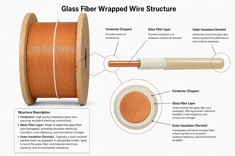
Fiberglass Covered Wire Material Properties
Glass fiber-covered magnet wire is a core insulation material for heavy-duty machinery windings, and its structure and performance determine equipment reliability.
Structure of Glass-Fiber-Insulated Magnet Wire
Standard constructions (e.g., NEMA MW 1000, MW 42-C):
- Conductor: Copper (bare or enameled)
- Base enamel coating: Class 130 enamel (polyester, modified polyester)
- Glass fiber layer: Electrical-grade continuous filament glass yarn braid
- Impregnating varnish treatment: Modified silicone, epoxy, polyester
- Surface finish: Smooth, semi-gloss, textured (depending on impregnating varnish)
Number of Layers:
- Single-layer glass fiber: simplest
- Double-layer glass fiber: standard solution
- Triple-layer glass fiber: high-grade
- Glass + enamel composite: double insulation
- Multi-layer composite: high-voltage applications
Conductor Materials
Copper Conductor:
- Round copper wire: 0.10–5.0 mm diameter
- Rectangular copper wire: 2–25 mm width × 1–10 mm thickness
- Base enamel coating: Polyester (130 °C), Polyester-imide (155 °C)
- High-strength copper: Tensile strength 200–250 MPa
- Oxygen-free copper: Electrical conductivity 100 % IACS+
Aluminum Conductor:
- Round aluminum wire: 0.20–5.0 mm
- Rectangular aluminum wire: width 2–25 mm × thickness 1–10 mm
- Base coating: identical to copper enamel coating
- Aluminum alloys: 1060, 3003, 5052
- Advantages: weight reduction, cost efficiency
- Limitations: termination/jointing processes
Glass Fiber Materials
Fiberglass Type:
- E-glass: Electrical-grade, most commonly used
- SiO₂: 54%
- CaO: 17%
- Al₂O₃: 15%
- B₂O₃: 8%
- Others: 6%
- S-glass: High-strength (aerospace)
- D-glass: Superior dielectric properties
- Fused quartz: Ultra-high temperature resistance
Glass Fiber Parameters:
- Fiber diameter: 5–13 μm
- Filament: Continuous filament
- Twist level: Low twist (excellent braiding performance)
- Dielectric strength: ≥10 kV/mm
- Temperature resistance: ≥500 °C (short-term)
- Tensile strength: 3000–5000 MPa
- Elastic modulus: 70–85 GPa
Glass Fiber Treatment:
- Desizing treatment: removal of spinning lubricants
- Surface treatment: silane coupling agent
- Antistatic treatment
- Waterproofing treatment
- Lubrication treatment
Base Film Material
Insulation Type and Temperature Class:
- Polyester (PEW): Class 130 (Class B)
- Modified Polyester (Modified PEW): Class 130+
- Polyester-imide (EIW): Class 155 (Class F)
- Polyamide-imide (AIW): Class 220 (Class C)
- Polyimide (PIW): Class 240
- Polyvinyl formal (PVF): Class 105
- Epoxy (EP): Class 130
Film Thickness:
- Grade 0: 0.020–0.030 mm
- Grade 1: 0.030–0.050 mm
- Grade 2: 0.050–0.080 mm (standard)
- Grade 3: 0.080–0.110 mm (maximum)
Impregnating Varnish Treatment
Impregnating Varnish Type:
– Modified silicone: Class C, 220°C+
– Silicone: Class H, 180°C
– Polyester (PE): Class F, 155°C
– Epoxy (EP): Class F–H
– Modified epoxy (Modified EP): Class H
– Polyester-imide (EI): Class F
Impregnating Varnish Process:
- Conventional impregnation: atmospheric-pressure varnish impregnation
- Vacuum pressure impregnation (VPI): high-pressure varnish impregnation
- Dip impregnation: simple immersion
- Drop impregnation: localized impregnation
- Roll impregnation: continuous roll impregnation
Impregnating Varnish Function:
- Bonding glass fiber layer
- Filling electrical gaps
- Moisture and water resistance
- Enhanced mechanical strength
- Increased breakdown voltage
- Improved thermal resistance
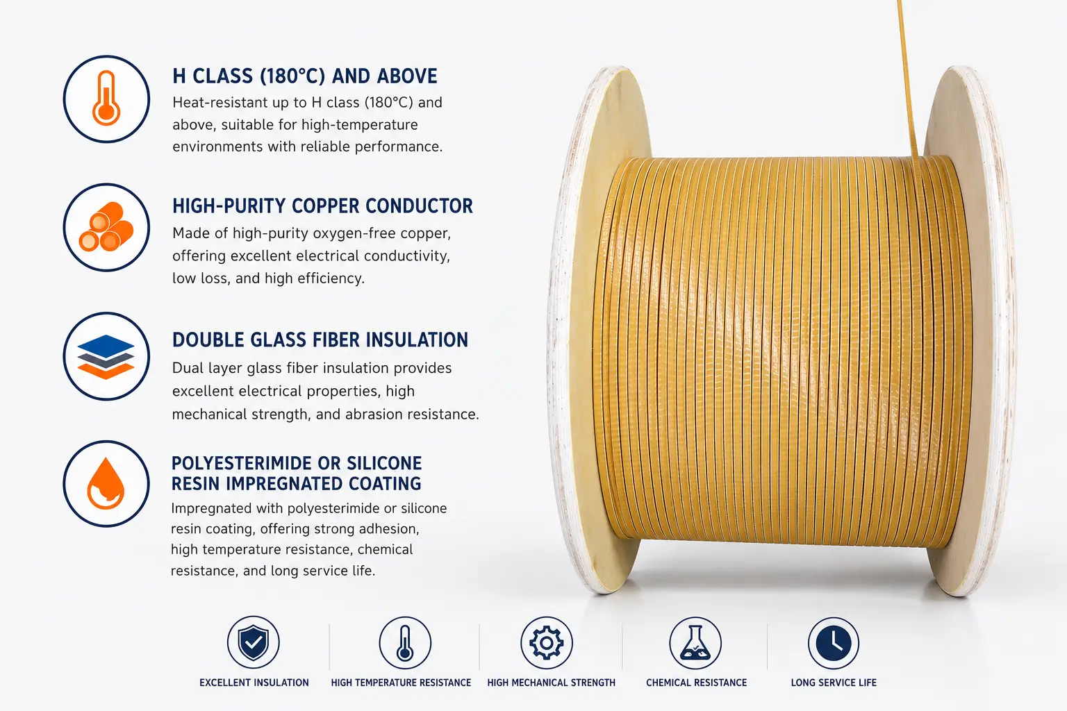
Performance Parameters of Glass-Fiber-Insulated Magnet Wire
Electrical Properties:
- Breakdown voltage: ≥10 kV (typical)
- Partial discharge: Low (Vd < 5 V)
- Dielectric loss: tan δ < 0.01
- Volume resistivity: >10¹² Ω·cm
- Surface resistivity: >10¹⁰ Ω
Thermal Performance:
- Long-term temperature resistance: Class H 180°C, Class C 220°C
- Short-term temperature resistance: 300°C+ (30 min)
- Thermal shock resistance: No cracking after cycling from –40°C to +200°C
- Thermal life: 20,000 hours @ 180°C
Mechanical Properties:
- Tensile strength: increased by 30–50% after coating
- Abrasion resistance: scratch-resistant
- Flexibility: no cracking at bending radius ≥3× wire diameter
- Vibration resistance: resistant to high-frequency vibration
Chemical Properties:
- Oil resistance: resistant to mineral oil and synthetic oil
- Acid and alkali resistance: resistant to weak acids and weak alkalis
- Solvent resistance: resistant to ethanol and acetone
- Water resistance: insulation performance remains unchanged after 24-hour immersion
- Flame retardancy: UL 94 V-0 rating
Fiberglass Covered Wire Manufacturing Process
The manufacturing process of fiberglass-covered magnet wire determines its performance stability.
Manufacturing Process Overview
Conductor drawing → Enamel coating → Glass fiber braiding → Impregnation with insulating varnish → Baking and curing → Testing → Packaging and warehousing
Step 1: Conductor Drawing
- Round copper rod: Φ8 mm
- Multi-pass drawing: 8 mm → 0.5–5.0 mm
- Intermediate annealing: 500–650 °C
- Final annealing: 350–450 °C (O temper)
- Surface cleaning: Removal of wire drawing lubricant
- Surface quality: Smooth, defect-free
Step 2: Primer Coating
- Pretreatment: pickling, cleaning
- Primer coating: polyester or polyester-imide
- Coating thickness: 0.020–0.080 mm
- Baking and curing: 300–400 °C
- Multi-layer coating (3–6 layers)
- In-line inspection: pinholes, thickness
Step 3: Fiberglass Braiding
Weaving method:
- Braiding: Diamond braid (standard)
- Wrapping: Helical wrapping
- Interweaving: Cross-braiding
- Bushing: Additional braided sleeve
Braiding Parameters:
– Braid density: 60–95 ends/m
– Braid angle: 45–65°
– Braid tension: 100–500 g
– Number of braided strands: 8, 12, 16, or 24 ends
– Braiding fiber fineness: 75–200 tex
Braiding Machine:
- Vertical braiding machine: Standard
- Horizontal braiding machine: High-speed
- CNC braiding machine: Premium
- Braiding speed: 5–30 m/min
Step 4: Impregnation Varnish Treatment
Impregnation Process:
- Conventional impregnation: atmospheric-pressure varnish impregnation for 1–5 minutes
- Vacuum impregnation: vacuum degassing for 30 minutes
- Pressure impregnation: impregnation under pressure of 0.2–0.5 MPa
- VPI: vacuum + pressure cycling
- Impregnation temperature: 20–40 °C
- Varnish viscosity for impregnation: 0.5–2.0 Pa·s
Baking Cure:
- Baking temperature: 120–180 °C (stepwise heating)
- Baking time: 4–12 hours
- Baking equipment: oven, tunnel furnace
- Cure degree control: gel time test
Step 5: Precision Inspection
In-line inspection:
– Enamel thickness: online laser thickness measurement
– Glass fiber integrity: visual inspection
– Impregnating varnish uniformity: surface inspection
– Outer diameter control: online diameter measurement
– Defect detection: 100% surface inspection
Performance Testing:
- Dielectric breakdown voltage test: ≥10 kV
- Dielectric loss test: tan δ
- Heat resistance test: 200 °C+ aging test
- Tensile strength test
- Flexibility test
Step 6: Finished Product Packaging
- Winding: Standard spool
- Packaging: Moisture-proof bag + desiccant
- Labeling: Specification, batch number, date of manufacture
- Protection: Moisture-proof, impact-resistant, corrosion-resistant
- Storage: Constant temperature and humidity environment
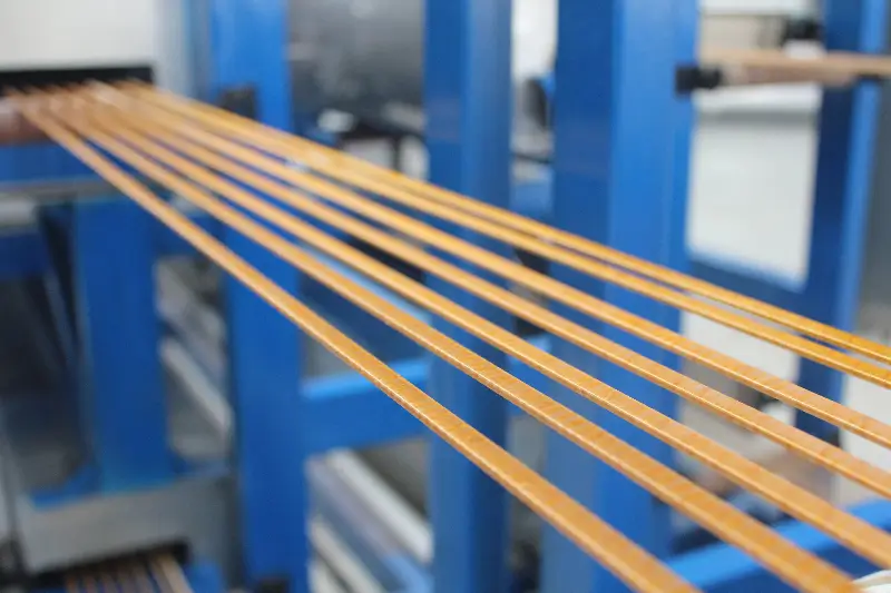
Fiberglass Covered Wire Insulation System
The application of fiberglass-covered magnet wire in heavy machinery requires a complete insulation system design.
Glass Fiber-Insulated Wire Classification
Classification by Thermal Class (NEMA MW 1000 Standard):
- MW 41-C: Glass fiber covering, Class 130 (Class B)
- MW 42-C: Glass fiber covering, Class 155 (Class F)
- MW 43-C: Glass fiber covering + polyester fiber, Class 155
- MW 44-C: Polyester-glass fiber covering, Class 180 (Class H)
- MW 45-C: Glass fiber covering + modified silicone varnish, Class 200
- MW 46-C: Glass fiber covering + silicone varnish, Class 220 (Class C)
Classification by Insulation Structure:
- Single-layer glass fiber: Standard Class F–H
- Double-layer glass fiber: High insulation class
- Glass fiber + enamel coating: Composite insulation
- Glass fiber + mica: Ultra-high voltage
- Glass fiber + polyimide (PI) film: Premium grade
Glass-Fiber-Insulated Magnet Wire Standards
U.S. Standard (NEMA MW 1000):
- MW 41-C: Class 130 Glass Fiber
- MW 42-C: Class 155 Glass Fiber
- MW 43-C: Class 155 Polyester-Glass
- MW 44-C: Class 180 Polyester-Glass
- MW 45-C: Class 200 Modified Silicone
- MW 46-C: Class 220 Silicone-Enamel Glass
IEC Standards:
- IEC 60317-30: Glass-fibre-covered round copper wire
- IEC 60317-31: Glass-fibre-covered rectangular copper wire
- IEC 60317-32: Glass-fibre-covered rectangular copper wire
Chinese National Standards (GB/T):
- GB/T 7672: Glass-fiber-covered magnet wire
- Identical adoption of IEC 60317 series
Japanese Industrial Standards (JIS):
- JIS C 3202: Glass-fiber-covered magnet wire
Technical Parameters of Glass-Fiber-Insulated Magnet Wire
| Specification Type | Thermal Class | Breakdown Voltage (kV) | Build-up (mm) | Application |
|---|---|---|---|---|
| MW 41-C | Class 130 | ≥5 | 0.10–0.20 | General-purpose motors |
| MW 42-C | Class 155 | ≥6 | 0.15–0.25 | Class F motors |
| MW 43-C | Class 155 | ≥6 | 0.15–0.25 | Class F moisture-resistant |
| MW 44-C | Class 180 | ≥8 | 0.20–0.30 | Class H motors |
| MW 45-C | Class 200 | ≥10 | 0.25–0.35 | Class C motors |
| MW 46-C | Class 220 | ≥12 | 0.30–0.40 | Extreme high-temperature applications |
Slot Insulation and Phase-to-Phase Insulation
Slot Insulation:
– Standards: DMD, NMN, NHN
– DMD: Polyester film + polyester fiber paper
– NMN: Polyester film + Nomex®
– NHN: Polyester film + Nomex® (high-temperature resistant)
– PI film: Polyimide (premium grade)
Phase-to-Phase Insulation:
- DMD, NMN, NHN
- End-tie binding: high-strength tie bands
- Slot wedges: epoxy, fiberglass
Impregnation Process:
- VPI: Vacuum Pressure Impregnation
- Dip: Conventional dip impregnation
- Impregnating varnish: Epoxy, silicone, modified silicone
End Tying and Reinforcement
End Ties:
– Polyester lacing tape: Class B
– Glass fiber lacing tape: Class H
– Aramid lacing tape: Class C (high strength)
End Reinforcement:
- Glass fiber sleeve
- End insulation box
- End insulation varnish
- End binding cord
Tying Process:
- Automatic wire tying machine
- Tying tension: controllable
- Tying density: standard + enhanced
Comparison Between Fiberglass Covered Wire and Other Insulation
Glass-fiber-covered magnet wire exhibits significant differences from other insulation materials across multiple dimensions.
Glass-Fiber-Insulated Wire vs. Pure Enamel-Coated Wire
| Dimension | Glass Fiber-Clad Wire | Pure Enamel-Coated Wire |
|---|---|---|
| Thermal Class | Class H 180°C / Class C 220°C | Classes B/F/H/C |
| Dielectric Strength | 10–15 kV | 4–8 kV |
| Mechanical Strength | Very High | Moderate |
| Vibration Resistance | Excellent | Moderate |
| Heat Dissipation | Excellent (glass fiber provides superior heat dissipation) | Moderate |
| Moisture Resistance | Good | Good |
| Cost | Higher | Lower |
| Diameter Increase | 0.20–0.40 mm | 0.05–0.10 mm |
| Slot Fill Factor | Lower | Higher |
| Processing Difficulty | Moderate | Easy |
Glass-Fiber-Insulated Wire vs Paper-Insulated Wire
| Dimension | Glass-Fiber-Insulated Wire | Paper-Insulated Wire |
|---|---|---|
| Thermal Class | Class H/C | Class A/E |
| Dielectric Strength | 10–15 kV | 5–10 kV |
| Moisture Resistance | Excellent | Poor |
| Mechanical Strength | Very High | Low |
| Vibration Resistance | Excellent | Fair |
| Application | Motors, Transformers | Oil-Immersed Transformers |
| Heat Dissipation | Excellent | Fair |
| Cost | Medium | Low |
| Substitution Relationship | Paper-insulated → Glass-fiber-insulated upgrade | Multi-layer paper insulation |
Glass-Fiber-Insulated Wire vs. Polyimide (PI) Film-Coated Wire
| Dimension | Glass Fiber-Insulated Wire | Polyimide (PI) Film-Insulated Wire |
|---|---|---|
| Thermal Class | Class H/C | 240°C+ |
| Dielectric Strength | 10–15 kV | 15–25 kV |
| Cost | Medium | High |
| Processability | Good | Poor |
| Diameter Increase | Large | Medium |
| Application | Heavy-Duty Machinery | High-End Motors |
| Application Scenario | Mainstream in Heavy-Duty Machinery | Aerospace |
Glass Fiber Wrapped Wire vs. Mica Tape
| Dimension | Glass Fiber-Insulated Wire | Mica Tape |
|---|---|---|
| Thermal Class | Class H/C | Above Class H |
| Dielectric Strength | 10–15 kV | ≥20 kV |
| Processability | Easy | Difficult |
| Cost | Medium | High |
| Application | Medium- and High-Voltage Motors | High-Voltage, Large-Scale Motors |
| Substitution Relationship | Mainstream for General Applications | For Extra-High-Voltage Applications |
Selection Decision Matrix
| Application Scenario | Preferred Solution | Alternative Solution |
|---|---|---|
| General-purpose motors (Class B/F) | Pure enamel coating | Glass fiber wrapped wire |
| Class F hoisting motors | Glass fiber wrapped wire | Pure enamel coating + composite |
| Class H metallurgical motors | Glass fiber wrapped wire | Polyimide (PI) film + enamel coating |
| Class C traction motors | High-grade glass fiber wrapped wire | Polyimide (PI) film |
| Welding transformers | Glass fiber wrapped wire | Paper wrapped + enamel coating |
| Electric furnace transformers | Glass fiber wrapped wire + mica | PI composite |
| High-voltage large motors | Glass fiber + mica tape | PI composite |
| Mining motors | Glass fiber wrapped wire | Polyimide (PI) film |
| Port hoisting motors | Glass fiber wrapped wire | Pure enamel coating |
Application of Fiberglass Covered Wire in Heavy Machinery Motor
The operating conditions for heavy-duty motors are extremely severe, and fiberglass-covered magnet wire is the mainstream solution for winding insulation.
Crane and Metallurgical Motors
Application Type:
- Main hoist crane motor: lifting, traveling, slewing
- Metallurgical rolling mill motor: rough rolling, finish rolling
- Foundry crane motor: molten steel ladle lifting
- Steelmaking furnace electrode motor
- Blower and compressor motor
Glass Fiber-Insulated Wire Specifications:
- Type: MW 42-C / MW 44-C
- Thermal Class: Class F 155°C / Class H 180°C
- Conductor: Round copper wire / Rectangular copper wire
- Diameter: 0.5–2.5 mm (round wire)
- Dimensions: Width 5–15 mm × Thickness 2–5 mm (rectangular wire)
- Dielectric Breakdown Voltage: ≥8 kV
- Impregnation: VPI
Typical Motor Parameters:
- Crane main motor: 50–500 kW, 690 V
- Rolling mill main motor: 1,000–12,000 kW, 3–10 kV
- Foundry crane motor: 200–500 kW, 690 V
- Steelmaking electrode motor: 300–1,500 kW, 690 V
Advantages of Fiberglass-Insulated Magnet Wire:
- Vibration resistance (cranes: 5–50 Hz)
- High-temperature resistance (metallurgy: ≥180 °C)
- Overload resistance (short-term: 2–3× rated current)
- Long service life (10–20 years)
Mining Motors
Application Type:
- Motor for mining scraper conveyor
- Motor for transfer machine
- Motor for crusher
- Motor for ball mill
- Motor for mine hoist
- Motor for mining truck
Glass Fiber-Insulated Wire Specifications:
- Type: MW 44-C (Class 180) / MW 46-C (Class 220)
- Conductor: Round copper wire / Rectangular copper wire
- Dielectric breakdown voltage: ≥10 kV
- Impregnation: Vacuum Pressure Impregnation (VPI)
- Reinforced end-tie
Mining Applications:
- Dust: coal dust, rock dust, cement dust
- Vibration: 5–200 Hz, 5–15 g
- Temperature: ambient ≥40 °C, winding 150 °C
- Humidity: relative humidity 95 %
- Flammable and explosive (in certain applications)
- Service life: >10 years
Typical Motor Parameters:
- Mining scraper motor: 100–2000 kW, 690 V–3 kV
- Mine hoist motor: 800–5000 kW, 3 kV–6 kV
- Crusher motor: 500–2000 kW, 6 kV
- Mining truck motor: 500–1500 kW, 800 V
Port Crane Motors
Application Type:
- Ship-to-shore (STS) container cranes
- Rubber-tired gantry (RTG) cranes
- Rail-mounted gantry (RMG) cranes
- Floating cranes, ship unloaders
- Port material handling motors
Glass Fiber-Insulated Wire Specifications:
- Type: MW 44-C (Class 180)
- Conductor: Round copper wire / Rectangular copper wire
- Dielectric breakdown voltage: ≥10 kV
- Impregnation: VPI
- Marine environment protection
Special Port Operating Conditions:
- Marine salt fog: severe corrosion
- High humidity: 85–95% RH
- Frequent start-stop cycles: 300–800 cycles/day
- High power: 100–3000 kW
- Long service life: 15–20 years
Typical Motor Parameters:
– STS main hoisting motor: 500–2000 kW, 690 V
– RTG motor: 100–300 kW, 400 V
– Ship unloader motor: 500–1500 kW, 690 V
Construction Machinery Motors
Application Type:
- Excavator motor (electric)
- Loader motor
- Bulldozer motor
- Crane motor (construction)
- Concrete pump truck motor
- Tunnel boring machine (TBM) motor
Glass Fiber-Insulated Magnet Wire Specifications:
- Type: MW 42-C / MW 44-C
- Conductor: Round copper wire / Rectangular copper wire
- Dielectric breakdown voltage: ≥8 kV
- Impregnation: Vacuum Pressure Impregnation (VPI) or conventional impregnation
- Reinforced insulation
Construction Machinery Operating Conditions:
- Road surface excitation: 5–30 Hz
- Vibration shock: 5–10 g
- High and low temperatures: –30 °C to +55 °C
- Dust: water, oil, sand
- Short-term overload: 2–3 times
Typical Motor Parameters:
– Large excavator motors: 200–800 kW, 800 V
– Loader motors: 50–200 kW, 400 V
– Tunnel boring machine cutter head motors: 500–2000 kW, 6 kV
– Crane motors: 50–500 kW, 400 V / 690 V
Application of Fiberglass Covered Wire in Heavy Transformer
Heavy-duty transformers represent another key application area for fiberglass-covered magnet wire.
Electric Furnace Transformer
Application Type:
- Arc Furnace Transformer
- Ore Smelting Furnace Transformer
- Induction Furnace Transformer
- Resistance Furnace Transformer
Glass-Fiber-Insulated Magnet Wire Specifications:
- Type: MW 44-C (Class 180) / MW 46-C (Class 220)
- Conductor: Rectangular copper wire (standard)
- Cross-section: Width 5–15 mm × Thickness 2–6 mm
- Dielectric breakdown voltage: ≥15 kV
- Impregnation: VPI (high vacuum)
- Reinforced insulation: Mica + glass fiber
Electric Furnace Transformer Characteristics:
- High current, low voltage
- Multiple voltage regulation steps
- Severe short-term overload
- High-temperature environment (above 60 °C near furnaces)
- Vibration (arc impact)
- Noise (arc discharge, magnetostriction)
Typical Electric Furnace Transformer Parameters:
- Capacity: 5000–100,000 kVA
- Primary voltage: 10–35 kV
- Secondary voltage: 100–1000 V
- Secondary current: 10,000–50,000 A
Rectifier Transformers
Application Type:
- Electrolytic aluminum rectifier transformer
- Electrolytic copper rectifier transformer
- Electrolytic zinc rectifier transformer
- Electroplating rectifier transformer
- Chlor-alkali rectifier transformer
Glass-Fiber-Insulated Magnet Wire Specifications:
- Type: MW 44-C (Class 180)
- Conductor: Rectangular copper wire
- Dielectric breakdown voltage: ≥15 kV
- Impregnation: Vacuum Pressure Impregnation (VPI)
- Corrosion protection (in selected applications)
Rectifier Transformer Characteristics:
- High current, low voltage
- Severe harmonics
- Continuous heavy load
- Long service life requirement
- Outdoor installation (partial)
Typical Rectifier Transformer Parameters:
- Capacity: 1000–50,000 kVA
- Primary voltage: 10–110 kV
- Secondary voltage: 100–1500 V
- Secondary current: 5,000–50,000 A
Traction Transformers
Application Type:
- Electric locomotive traction transformer
- High-speed railway traction transformer
- Metro traction transformer
- Industrial and mining electric locomotive traction transformer
Glass Fiber-Insulated Wire Specifications:
- Type: MW 44-C / MW 46-C
- Conductor: Rectangular copper wire
- Dielectric breakdown voltage: ≥15 kV
- Impregnation: VPI
- Reinforced banding (vibration resistance)
Traction Transformer Characteristics:
- High vibration (train vibration)
- Frequent overload (start-up, acceleration)
- High temperature (machine room >50°C)
- Compact design
- Long service life (30 years)
Typical Traction Transformer Parameters:
- Capacity: 1000–10,000 kVA
- Primary voltage: 25 kV (overhead catenary)
- Secondary voltage: 1500 V DC or 750 V DC
- Overload capability: 2–3 times rated current for 5 minutes
Large Industrial Transformers
Application Type:
- Large rectifier transformers
- Large electric furnace transformers
- Large traction transformers
- Industrial main transformers
- Test transformers
Glass Fiber-Insulated Wire Specifications:
- Type: MW 46-C (Class 220)
- Conductor: Rectangular high-strength copper wire
- Dielectric breakdown voltage: ≥20 kV
- Impregnation: Vacuum Pressure Impregnation (VPI)
- Composite insulation (glass fiber + mica)
Application of Fiberglass Covered Wire in Welding Equipment
Transformers and coils for welding equipment represent a traditional application of fiberglass-covered magnet wire.
Welding Machine Transformers
Application Type:
- Arc welder transformers
- Submerged arc welder transformers
- TIG/MIG welder transformers
- Resistance welder transformers
- Plasma welder transformers
Glass Fiber-Insulated Wire Specifications:
- Type: MW 42-C / MW 44-C
- Conductor: Rectangular copper wire (round copper wire less common)
- Dielectric breakdown voltage: ≥8 kV
- Impregnation: Vacuum Pressure Impregnation (VPI)
- Reinforced insulation
Welding Machine Transformer Characteristics:
- High current, low voltage
- Frequent no-load to load switching
- Severe vibration (welding gun movement)
- High temperature (welding gun, arc light)
- Intermittent duty cycle (e.g., 60% duty cycle)
Typical Welding Machine Transformer Parameters:
- Capacity: 10–500 kVA
- Primary voltage: 380 V
- Secondary voltage: 20–80 V
- Current: 100–1500 A
Resistance Welding Transformers
Application Type:
- Spot welding transformers
- Projection welding transformers
- Seam welding transformers
- Butt welding transformers
Glass Fiber-Insulated Wire Specifications:
- Type: MW 44-C (Class 180)
- Conductor: Rectangular copper wire
- Dielectric breakdown voltage: ≥10 kV
- Impregnation: Vacuum Pressure Impregnation (VPI)
- Forced water cooling (partial)
Resistance Welding Transformer Characteristics:
- Very low voltage (a few volts)
- Very high current (kiloamperes)
- Short-time operation (welding trigger)
- Intensive cooling (water cooling)
- Vibration
Induction Heating Transformers
Application Type:
- Medium-frequency induction heating transformer
- High-frequency induction heating transformer
- Power-frequency induction heating transformer
- Through-heating induction heating transformer
Glass Fiber-Insulated Wire Specifications:
- Type: MW 44-C / MW 46-C
- Conductor: Round copper tube (Litz wire)
- Dielectric breakdown voltage: ≥10 kV
- Impregnation: VPI or epoxy casting
- Water-cooled
Electroslag Furnace Transformer
Application Type:
- Electroslag Remelting (ESR) Furnace Transformer
- Electroslag Casting Transformer
- Plasma Electroslag Remelting (PESR) Furnace Transformer
Glass Fiber-Insulated Wire Specifications:
- Type: MW 46-C (Class 220)
- Conductor: Rectangular copper wire
- Dielectric breakdown voltage: ≥15 kV
- Impregnation: Vacuum Pressure Impregnation (VPI)
- Reinforced insulation
Industrial Heating Transformers
Application Type:
- Power-frequency induction melting furnace transformer
- Medium-frequency induction melting furnace transformer
- Vacuum induction furnace transformer
- Single-crystal furnace transformer
Glass-Fiber-Insulated Magnet Wire Specifications:
- Type: MW 44-C / MW 46-C
- Conductor: Large-size rectangular copper wire
- Dielectric breakdown voltage: ≥15 kV
- Impregnation: Vacuum Pressure Impregnation (VPI)
- Reinforced insulation
Fiberglass Covered Wire Selection Decision
Selection of fiberglass-covered magnet wire is a core step in engineering design.
Selection Decision Tree
Decision 1: Thermal Class (Temperature Rating)
- Class B 130°C: General applications
- Glass fiber wrap: MW 41-C
- Enamel coating: PEW
- Class F 155°C: Standard Class F motors
- Glass fiber wrap: MW 42-C / MW 43-C
- Enamel coating: EIW
- Class H 180°C: Standard Class H motors
- Glass fiber wrap: MW 44-C
- Enamel coating: AIW
- Class C 220°C: Extreme high-temperature applications
- Glass fiber wrap: MW 45-C / MW 46-C
- Enamel coating: PIW
Decision 2: Voltage Class
- ≤400 V: Thin insulation
- Glass-fiber-covered wire: Double-layer
- Dielectric breakdown voltage: ≥5 kV
- 400 V–690 V: Standard insulation
- Glass-fiber-covered wire: Double-layer reinforced
- Dielectric breakdown voltage: ≥8 kV
- 690 V–3 kV: High insulation
- Glass-fiber-covered wire: Triple-layer
- Dielectric breakdown voltage: ≥10 kV
- 3 kV–10 kV: Ultra-high insulation
- Glass-fiber-covered wire: High-grade + mica
- Dielectric breakdown voltage: ≥15 kV
- ≥10 kV: Extra-high voltage
- Glass-fiber-covered wire: Polyimide (PI) composite + mica
- Dielectric breakdown voltage: ≥20 kV
Decision 3: Environment and Lifetime
- General environment: Standard glass-fiber insulated wire
- High humidity: Reinforced glass-fiber insulated wire + moisture-resistant varnish
- Marine: Salt-spray resistant glass-fiber insulated wire
- Chemical corrosion: Corrosion-resistant glass-fiber insulated wire
- High dust: Glass-fiber insulated wire + sealing
- Explosion-proof: Flame-retardant glass-fiber insulated wire
Decision 4: Mechanical Requirements
– Standard vibration: standard tie
– Severe vibration (5–15 g): reinforced tie
– High shock: fiberglass tie tape + insulation tubing
– Long service life: VPI reinforcement
Decision 5: Cost Budget
- Economy grade: MW 42-C (Class 155)
- Standard grade: MW 44-C (Class 180)
- Premium grade: MW 46-C (Class 220)
Glass Fiber-Clad Wire vs. Pure Enamel Coating Selection Equivalence
| Application | Solid Enamel Grade | Fiberglass-Overcoated Grade |
|---|---|---|
| General-purpose motors | MW 35-C (Class 130) | MW 41-C |
| Class F motors | MW 74-C (Class 155) | MW 42-C / MW 43-C |
| Class H motors | MW 80-C (Class 180) | MW 44-C |
| Class C motors | MW 76-C (Class 220) | MW 45-C / MW 46-C |
| Heavy-duty motors | MW 84-C (Class 200) | MW 44-C |
| Traction motors | MW 30-C (Class 220) | MW 46-C |
Glass Fiber-Clad Wire Specifications Equivalence Table
| Glass Fiber Covered Wire | Equivalent Enamel Base | Equivalent Thermal Class | Equivalent Impregnating Varnish |
|---|---|---|---|
| MW 41-C | PEW | 130 | PE |
| MW 42-C | EIW | 155 | PE / EP |
| MW 43-C | EIW | 155 | PE (Polyester Fiber-Enhanced) |
| MW 44-C | AIW | 180 | Modified EP |
| MW 45-C | PIW | 200 | Modified Silicone |
| MW 46-C | PIW | 220 | Silicone Varnish |
Special Selection for Heavy-Duty Machinery
Extreme High Temperature:
- Recommended: MW 46-C (Class 220)
- Applications: Metallurgy, electric furnaces
- Reinforcement: Increased fiberglass layer count
- Impregnation: Modified silicone varnish
Strong vibration:
- Recommended: MW 44-C (Class 180)
- Applications: Lifting, excavation
- Reinforcement: End-tie reinforcement
- Impregnation: VPI reinforcement
Marine Environment:
- Recommended: MW 44-C (Class 180) + corrosion protection
- Application: Port cranes
- Reinforcement: Salt fog–resistant coating
- Impregnation: Humidity and heat resistant
Coal Mine Methane:
– Recommended: MW 44-C (Class 180) + Explosion-Proof
– Application: Mining Motors
– Reinforcement: Flame-Retardant Treatment
– Impregnation: Flame-Retardant Varnish
Next to metallurgical furnace:
- Recommended: MW 45-C / MW 46-C
- Application: Electric furnace transformers
- Reinforcement: High-temperature glass fiber
- Impregnation: Modified silicone / organosilicone
Fiberglass Covered Wire Failure Modes and Quality Control
Common Failure Modes
Failure 1: Glass Fiber Abrasion
- Cause: Prolonged vibration, foreign object embedding
- Phenomenon: Glass fiber layer damage
- Location: End turns, slot openings
- Detection: Visual inspection, sectioning
- Prevention: Standard tying, clean production
Failure 2: Insulation Film Damage
- Cause: Excessive bending stress, mechanical damage
- Phenomenon: Enamel coating cracking, reduced dielectric breakdown voltage
- Detection: Dielectric breakdown voltage test
- Prevention: Maintain appropriate bending radius, avoid mechanical damage
Failure 3: Impregnating Varnish Aging
- Cause: Prolonged high temperature and chemical corrosion
- Phenomenon: Powdering and delamination of impregnating varnish
- Inspection: Visual examination and adhesion testing
- Prevention: Selection of impregnating varnish with appropriate thermal class
Failure 4: Loose End Windings
- Cause: Vibration fatigue, insufficient tying
- Phenomenon: Winding loosening, insulation wear
- Detection: Vibration testing, impedance measurement
- Prevention: Reinforced tying
Failure 5: Loose Winding in Slot
- Causes: Electromagnetic forces, thermal expansion
- Phenomena: Slot wedge loosening, winding deformation
- Detection: Vibration testing
- Prevention: Slot wedge optimization, enhanced binding
Failure 6: Breakdown Voltage Reduction
- Causes: Moisture absorption, mechanical damage, aging
- Symptoms: Failure to meet insulation test requirements
- Detection: Dielectric breakdown voltage testing
- Prevention: Moisture-proof packaging, proper storage
Failure 7: Turn-to-turn short circuit
- Cause: Bending stress, insulation film damage
- Phenomenon: Local current anomaly
- Detection: Turn-to-turn test
- Prevention: Proper forming process
Failure 8: Glass Fiber Moisture Absorption
- Cause: Humid storage environment
- Phenomenon: Degradation of insulation performance
- Detection: Moisture absorption test
- Prevention: Moisture-proof packaging
Failure 9: Heating of Connection Terminals
- Cause: Poor connection process
- Phenomenon: Terminal heating and discoloration
- Detection: Infrared temperature measurement
- Prevention: Standardization of the connection process
Failure 10: Overall Winding Deformation
- Cause: Extreme overload, excessive winding temperature
- Phenomenon: Winding deformation, short circuit
- Detection: Visual inspection, electrical testing
- Prevention: Proper product selection, overload protection
Quality Control System
Raw Material Quality Control:
- Glass fiber: composition, twist, tensile strength
- Enamel coating: adhesion, dielectric breakdown voltage
- Impregnating varnish: viscosity, solids content
- Conductor: composition, dimensions, performance
Process Quality Control:
- Braiding density: 100% online inspection
- Braiding angle: CCD inspection
- Impregnating varnish uniformity: visual inspection + weighing
- Baking cure degree: gel time
- Online: DC resistance, inductance
Finished Product Quality Control:
- Breakdown voltage: ≥ specified value
- Dielectric loss: tan δ test
- Heat resistance test: aging at 200°C+
- Tensile strength: universal testing machine
- Flexibility: bend radius test
Special Testing for Heavy-Duty Machinery:
- Vibration test: 5–50 Hz, 1–15 g
- Shock test: ≥50 g
- Temperature cycling: −40 °C to +180 °C
- Damp heat test: 95 % RH, 168 h
- Salt spray test: 96 h (marine)
- Dust test: dusty environment
Quality Assurance System:
- ISO 9001: Fundamental quality
- IATF 16949: Automotive industry (including certain heavy machinery)
- ISO 14001: Environmental management
- IEC 60093 / IEC 60243: Dielectric strength
- ASTM D3032: Cable voltage endurance
- IEC 60317: Enamelled wire standards
Special Requirements and Future Trends of Heavy Machinery
Special Requirements for Heavy-Duty Machinery
Vibration and Shock Requirements:
- Vibration frequency: 5–200 Hz
- Acceleration: 1–15 g
- Shock: ≥50 g, short-term
- Continuous vibration endurance: >100,000 hours
- End-winding tie-down: vibration-resistant reinforcement
- Slot wedges: high-strength
- Impregnation: vacuum pressure impregnation (VPI) reinforcement
Temperature Cycling Requirements:
- Operating temperature: –40 °C to +55 °C (outdoor)
- Storage temperature: –40 °C to +50 °C
- Start-up temperature: –30 °C cold start
- Winding hot spot: 120–180 °C
- Temperature ramp rate: 20 °C/min
- Cycle count: >5,000 cycles/year
Dust and Contamination Requirements:
- Dust types: coal dust, cement dust, rock dust, oil fume
- Dust protection rating: IP54–IP65
- Protective measures: sealing, filtration
- Insulation coating: pollution flashover resistance
Chemical corrosion requirements:
- Marine salt spray: 96–500 hours
- Acid mist: resistant to weak acids
- Alkali mist: resistant to weak alkalis
- Mineral oil: oil-resistant
- Coolant: glycol-resistant
Explosion-Proof Requirements (Coal Mines, Chemical Industry):
- Explosion protection rating: Ex d I Mb (coal mine)
- Explosion protection rating: Ex d IIB T4 (chemical industry)
- Surface temperature: ≤150 °C (T4)
- Winding resistance: ≤ specified value
- Insulation test: specified value
Extended Service Life Requirement:
– Design life: 10–20 years
– Operating time: >50,000 hours
– Heavy-duty operation: >10,000 hours/year
– Maintenance interval: Long interval (>2 years)
– Spare parts availability: Long-term supply
Future Development Trends
Trend 1: Higher Thermal Class
- Class C, 220°C+ has become the mainstream for high-end applications
- New insulation materials (Class H and above)
- 240°C (polyimide composite) is becoming widespread
- 260°C+ (mica + glass)
Trend 2: 800 V / 1000 V High-Voltage Platforms
– Electrification trend in heavy-duty machinery
– 800 V systems gaining widespread adoption
– 1000 V platform under testing
– Enhanced insulation class for fiberglass-covered magnet wire
Trend 3: New Glass Fibers
- High-strength glass fiber
- Nano-modified glass fiber
- Flame-retardant glass fiber
- Dielectric-optimized glass fiber
Trend 4: Automated Winding
- CNC automatic winding machine
- In-line inspection + automatic rework
- Digital twin
- Smart factory
Trend 5: Online Monitoring and Predictive Maintenance
- Online insulation monitoring
- Partial discharge monitoring
- Temperature monitoring
- Vibration monitoring
- AI-based fault prediction
Trend 6: Environmentally Friendly Insulation Materials
- Water-based impregnating varnish
- Solvent-free impregnating varnish
- Bio-based impregnating varnish
- Low VOC emissions
- Compliant with RoHS/REACH
Trend 7: High-Voltage Specialty Glass-Fiber-Insulated Magnet Wire
- 10 kV+ glass-fiber-covered magnet wire
- Extra-high-voltage glass-fiber-covered magnet wire
- Composite insulation system (glass fiber + polyimide)
- High-dielectric-strength glass fiber
Trend 8: Lightweighting and High Power Density
- Novel lightweight impregnating varnish
- Glass fiber weight reduction
- Enhanced power density
- Large motor windings
Conclusion
Glass fiber-covered magnet wire serves as a core insulation material for windings in heavy-duty machinery. Compared with pure enamel-coated wire, it offers significant advantages including high-temperature resistance (Class H: 180°C / Class C: 220°C), high dielectric strength (≥10 kV), superior mechanical strength, excellent impact and vibration resistance, and outstanding heat dissipation performance. It is a critical insulation solution for heavy-duty applications such as hoisting motors, metallurgical motors, mining motors, port cranes, welding transformers, and electric furnace transformers.
Key considerations for fiberglass-covered magnet wire applications in heavy machinery:
- Understanding the characteristics of heavy-duty machinery: Differences from standard motors include frequent start-stop cycles, heavy-load overloading, vibration and impact, dusty environments, and extended service life requirements.
- Mastering the fiberglass-covered wire construction: A multi-layer composite structure comprising conductor + enamel coating + fiberglass layer + impregnating varnish.
- Familiarity with the standards system: NEMA MW 1000 (MW 41–46), IEC 60317, GB/T 7672.
- Correct thermal class selection: Thermal classes F, H, and C cover the mainstream thermal classes for heavy-duty machinery.
- Emphasis on insulation systems: Fiberglass-covered wire + slot insulation + end-winding tie-down + vacuum pressure impregnation (VPI).
- Application-specific design: Distinct design priorities for crane, mining, port, and metallurgical applications.
- Rigorous quality control: Raw materials + in-process controls + finished products + heavy-duty machinery-specific testing.
- Awareness of future trends: Higher thermal classes, 800 V / 1000 V systems, novel fiberglass materials, and automated manufacturing.
Engineers, designers, procurement personnel, and operation & maintenance staff for heavy-duty machinery motors/transformers shall progressively master the application of fiberglass-covered magnet wire in heavy-duty machinery through systematic learning (fiberglass covering material systems, standards systems—including IEC 60317, NEMA MW 1000, ASTM B566, UL 1446—and manufacturing processes), supplier collaboration (fiberglass yarn manufacturers, enameled wire producers, winding manufacturers), quality control (incoming material inspection, in-process control, finished product testing, special testing), and technology tracking (new fiberglass materials, new impregnating varnishes, new applications), thereby providing core insulation support for high reliability, long service life, and safe operation of heavy-duty machinery used in lifting, metallurgy, mining, port handling, and welding.