
Introduction
Fiberglass covered wire, as an important electrical insulation material, plays an irreplaceable and crucial role in the field of electrical engineering. With the rapid development of modern industrial technology and the continuous improvement of the performance requirements of electrical equipment, fiberglass covered wire, with its excellent high-temperature resistance, superior electrical insulation properties, good mechanical strength, and outstanding chemical stability, has become an indispensable core material in high-voltage motors, transformers, reactors, welding equipment, and various special electrical equipment. Electrical engineering is the cornerstone of modern industry. From power generation, transmission and distribution to power consumption terminals, from industrial production to daily life, the reliable operation of electrical equipment is directly related to economic development and social efficiency.
Against this backdrop, a deep understanding of the technical characteristics, application areas, selection criteria, and development trends of fiberglass covered wire is of significant practical value for electrical engineers, product developers, and equipment maintenance technicians. This article will provide a systematic overview of the application of fiberglass covered wire in electrical engineering, offering comprehensive technical reference for relevant engineering and technical personnel.
II. Basic Concepts of Fiberglass-Coated Wire
2.1 Definition and Structural Characteristics
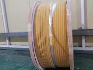
Fiberglass-coated wire is an insulated conductor with a copper or aluminum metal conductor as the matrix and an outer layer of fiberglass material wound through a special process. From a materials science perspective, fiberglass is an inorganic non-metallic material, mainly composed of silicon dioxide, and possesses excellent heat resistance, insulation, and mechanical strength properties. Structurally, fiberglass-coated wire typically exhibits a multi-layered composite structure. The first layer is a conductive metal conductor, usually made of electrolytic copper, oxygen-free copper, or aluminum alloy.
The conductor cross-section can be circular, flat, or rectangular to adapt to different application requirements and winding process requirements. The second layer is the inner insulation layer, usually formed by a precision winding process of fiberglass filaments. The specifications of the fiberglass filaments and the winding density directly affect the insulation performance. The third layer is the outer protective layer, usually a protective coating formed by impregnation with insulating varnish and subsequent curing, used to enhance wear resistance, moisture resistance, and overall mechanical strength.
According to international standards and industry specifications, the naming and labeling of fiberglass-coated wire typically includes key technical parameters such as conductor material, conductor size, insulation class, and fiberglass type. For example, common labeling methods clearly indicate the conductor diameter or cross-sectional area, insulation thermal class (e.g., F class 155°C, H class 180°C, C class above 200°C), and structural form (single-layer coating, double-layer coating, etc.).
2.2 Differences from Other Insulated Wires
In the field of electrical engineering, there are many types of insulated wires, including enameled wire, paper-insulated wire, cotton-insulated wire, and fiberglass-coated wire. These types of insulated wires differ significantly in material properties, manufacturing processes, and applicable scenarios. Enameled wire uses organic resin materials to form an insulation layer through a coating and baking process. The insulation layer is continuous, uniform, and smooth.
Production lines are fast and relatively low-cost, making it suitable for general motors, transformers, and general industrial applications. The operating temperature is typically in the range of 130°C to 180°C. Fiberglass-coated wire uses inorganic glass fiber materials to form an insulation layer through a wrapping and impregnation process. This insulation layer exhibits a distinct fibrous structure.
Although the production line is slower and the process is more complex, it achieves higher insulation levels and better heat resistance, with operating temperatures reaching 200°C to 260°C or even higher. Paper-coated wire uses cable paper as the insulation layer and is mainly used in traditional electrical equipment such as oil-immersed transformers. Its heat resistance and mechanical strength are inferior to fiberglass-coated wire. Yarn-coated wire uses cotton yarn or synthetic fiber filaments for wrapping, resulting in relatively limited insulation performance and heat resistance.
It is mainly used in general electrical products and household appliances. Compared to the above-mentioned types of insulated wires, fiberglass-coated wire has significant advantages in overall performance, especially in applications requiring high temperature, high pressure, and high reliability, where it is an irreplaceable choice.
III. Technical Characteristics of Fiberglass-Coated Wire
3.1 Heat Resistance
Heat resistance is one of the most prominent technical advantages of fiberglass-coated wire. As an inorganic material, glass fiber typically has a melting point above 800°C to 1000°C. Within its normal operating temperature range, it does not undergo thermal decomposition, softening, or performance degradation, providing a fundamental guarantee for the reliable operation of glass fiber-coated wire in high-temperature environments. According to international standards such as IEC 60317 and NEMA MW 1000, glass fiber-coated wire is clearly divided into several thermal classes.
Class F insulation (155°C class) uses modified polyester impregnation varnish or polyester-imide impregnation varnish, with a maximum continuous operating temperature of 155°C, suitable for general industrial motors and transformers with relatively low heat resistance requirements. Class H insulation (180°C class) uses silicone impregnation varnish or polyamide-imide impregnation varnish, with a maximum continuous operating temperature of 180°C. This is currently the most widely used type of glass fiber-coated wire, offering excellent overall performance and good cost-effectiveness. Class C insulation (above 200°C) uses polyimide resin, polytetrafluoroethylene, or special silicone materials, with a maximum continuous operating temperature of 240°C to 300°C.
It is mainly used in extreme high-temperature environments such as aerospace, deep well drilling, and steel metallurgy. In practical engineering applications, the instantaneous heat resistance of fiberglass-coated wire is also noteworthy. Under short-term over-temperature conditions, high-quality fiberglass-coated wire can withstand temperature shocks of 300°C or even higher without insulation damage, which is of great significance for coping with sudden load changes and abnormal operating conditions.
3.2 Electrical Insulation Performance
Fiberglass-coated wire exhibits excellent electrical insulation performance, which is an important basis for its widespread application in high-voltage electrical equipment. In terms of breakdown voltage, the typical dielectric strength of fiberglass materials can reach 20 kV/mm to 40 kV/mm. After vacuum impregnation and curing, the overall breakdown voltage of fiberglass-coated wire can be further increased to a higher level, fully meeting the insulation strength requirements of high-voltage motors (3kV to 10kV) and power transformers. In extreme high-voltage applications, even higher breakdown voltage levels can be achieved by increasing the insulation thickness or using a multi-layer coating structure.
Regarding insulation resistance, fiberglass-coated wire exhibits extremely high insulation resistance values in the dry state, typically exceeding 10^12 Ω·cm. Even under harsh environmental conditions of high temperature and high humidity, the decrease in insulation resistance is relatively limited, thanks to the stable chemical properties of the fiberglass material itself and the continuous protective layer formed by the impregnation varnish. In terms of dielectric loss, the dielectric loss tangent (tanδ) of fiberglass material is low, typically in the range of 0.001 to 0.01. Low dielectric loss means that in AC high-voltage electric fields, a smaller proportion of energy is lost as heat, which is beneficial for improving the operating efficiency of electrical equipment and reducing heat generation.
Regarding partial discharge performance, high-quality fiberglass-coated wire exhibits excellent resistance to partial discharge. Partial discharge is one of the main causes of aging in high-voltage insulation materials. The dense structure and excellent impregnation effect of glass fiber coated wire can effectively suppress the generation and development of partial discharge, extending the insulation life.
3.3 Mechanical Properties
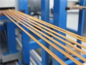
The mechanical properties of glass fiber coated wire are another important advantage, providing reliable protection for winding processing and equipment operation. In terms of tensile strength, glass fiber filaments have very high tensile strength, typically ranging from 1000 MPa to 3000 MPa. This characteristic allows the glass fiber coated wire to withstand large tensions during winding without elongation or breakage, which is beneficial for achieving high-speed, high-precision automated winding production. In terms of abrasion resistance, after impregnation and curing treatment, a hard protective layer is formed on the surface of the glass fiber coated wire, exhibiting excellent abrasion resistance.
During the high-speed operation of automated winding equipment, the conductor needs to withstand large frictional forces and mechanical stresses; excellent abrasion resistance can effectively prevent premature failure caused by damage to the insulation layer. Regarding flexibility, while fiberglass-coated wire is not as flexible as enameled wire, it can meet most application requirements through proper structural design. For example, using a multi-strand stranded conductor structure can significantly improve flexibility, making it suitable for complex coil shapes that require bending. For applications with extremely high flexibility requirements, specially designed flexible fiberglass-coated wire products can be selected.
In terms of impact resistance, fiberglass-coated wire can withstand certain mechanical shocks and vibration loads, making it suitable for electrical equipment operating under vibration conditions, such as traction motors and mining machinery.
3.4 Chemical Stability
Fiberglass-coated wire exhibits good chemical stability, maintaining stable performance in various harsh chemical environments. Regarding oil resistance, specially impregnated fiberglass-coated wire can withstand long-term immersion in mineral oils such as transformer oil, lubricating oil, and hydraulic oil, making it suitable for applications such as oil-immersed transformers and oil-immersed reactors. The selection of impregnating varnish needs to be specifically matched according to the chemical properties of the specific oil medium. In terms of corrosion resistance, fiberglass materials exhibit good resistance to most acids, alkalis, and salts, only corroding under extreme conditions such as hydrofluoric acid and hot concentrated alkalis.
This characteristic makes fiberglass-coated wire suitable for corrosive environments such as chemical, marine, and metallurgical industries. Regarding weather resistance, fiberglass-coated wire possesses excellent resistance to UV aging and atmospheric corrosion, making it suitable for outdoor electrical equipment and long-term exposure environments. In terms of moisture resistance, although fiberglass itself has a certain degree of hygroscopicity, the continuous protective layer formed after impregnation treatment effectively prevents moisture intrusion. For applications with extremely high moisture resistance requirements, fiberglass-coated wire products with hydrophobic treatment or special sheaths can be selected.
IV. Typical Applications of Fiberglass-Coated Wire in Electrical Engineering
4.1 High-Voltage Motor Field
High-voltage motors are one of the most important application areas for fiberglass-coated wire. For AC and DC motors with rated voltages ranging from 3kV to 10kV or even higher, the windings must withstand high electrical stresses. Fiberglass-coated wire, with its excellent insulation performance and heat resistance, has become the standard choice for high-voltage motor windings. In high-voltage asynchronous motors, fiberglass-coated wire windings need to withstand the combined effects of high voltage, high current, and complex electromagnetic forces.
The design of the winding insulation needs to consider multiple factors such as operating voltage, surge voltage, partial discharge, heat accumulation, and mechanical vibration. The reliable insulation performance and long lifespan of fiberglass-coated wire are crucial for the safe and stable operation of high-voltage motors. In high-voltage permanent magnet synchronous motors, the requirements for winding power density and heat dissipation are even higher. Fiberglass-coated wire not only withstands high-voltage insulation requirements, but its excellent heat resistance also provides technical support for increasing current density and achieving motor miniaturization.
In the field of traction motors, the drive motors of mobile devices such as rail transit vehicles and electric vehicles have extremely high reliability requirements and must withstand complex operating conditions such as vibration, shock, and temperature cycling. Fiberglass-coated wire has wide applications in the traction motor field and is a key material for ensuring the long-term reliable operation of traction systems.
4.2 Transformer Field
Transformers are another important application area for fiberglass-coated wire. From power transformers used in power system transmission and distribution, to distribution transformers used in industrial power distribution, and to rectifier transformers and electric furnace transformers used in special applications, fiberglass-coated wire plays a crucial role. In oil-immersed power transformers, the winding conductors typically use paper-insulated or glass fiber-insulated structures, forming a complete insulation system together with the transformer oil. The combination of fiberglass-coated wire and transformer oil allows it to withstand long-term high voltage, high current, and temperature cycling.
Transformer oil has excellent insulation performance and heat dissipation properties; when used in conjunction with fiberglass-coated wire, reliability is further enhanced. In dry-type transformers, the windings are treated with a vacuum impregnation process. The entire glass fiber-coated wire winding is immersed in high-performance insulating varnish and then cured to form a robust insulating whole. Dry-type transformers have advantages such as fire resistance, explosion resistance, and no pollution, making them particularly suitable for high-rise buildings, hospitals, data centers, subways, and other places with high safety requirements.
H-class insulation (180°C class) dry-type transformers are currently the mainstream products on the market. In electric furnace transformers and rectifier transformers, the windings need to withstand large currents and frequent load cycles, requiring higher thermal stability and mechanical strength of the insulation materials. Glass fiber-coated wire, with its excellent performance, is an ideal choice for these special transformers.
4.3 Reactors and Filters
Reactors and filters are important equipment in power systems and reactive power compensation devices, and glass fiber-coated wire is also widely used in these devices. In high-voltage parallel reactors, they are used to compensate for the capacitive reactive power of transmission lines, reduce overvoltage, and suppress resonance. Reactor windings need to withstand high voltage and long-term loads, and the selection of insulation materials directly affects the equipment’s lifespan and operational reliability. In series reactors, used in series with capacitor banks, they limit inrush current and suppress harmonic currents.
Series reactors operate at large currents, requiring high current density and heat dissipation performance from the conductors. In filters, they are used to filter out specific harmonic currents in the power system, improving power quality. Filter windings need to operate stably under high-frequency harmonic currents. For all types of reactors and filters mentioned above, fiberglass-coated wire, with its excellent electrical insulation performance and heat resistance, ensures the safe and reliable operation of the equipment.
4.4 Welding Machines and Electric Heating Equipment
Welding equipment is a traditional application area for fiberglass-coated wire. Electric welding machines generate a large amount of heat during operation, and the welding machine transformer and reactor windings need to withstand high temperature rises. The heat resistance advantage of fiberglass-coated wire is fully utilized here. In resistance welding machines, welding is performed by generating heat through a large current flowing through the workpiece contact point.
The welding transformer withstands large short-circuit currents and thermal shocks. Fiberglass-coated wires maintain stable performance under harsh conditions of continuous high-load operation. In arc welding machines, whether manual arc welding, gas shielded welding, or submerged arc welding, the welding machine (transformer) needs to continuously provide a large current output. The reliability of fiberglass-coated wires ensures the stable operation of the welding machine under long-term high-load conditions.
In electric furnace equipment, including induction furnaces, resistance furnaces, and electric arc furnaces, the furnace (transformer) and induction coils need to withstand extremely high temperatures and complex electromagnetic forces. For these extreme applications, Class C insulation (above 200°C) special fiberglass-coated wire products are typically required.
4.5 Other Electrical Engineering Applications
In addition to the main application areas mentioned above, fiberglass-coated wires are also widely used in many other electrical engineering fields. In the rail transit sector, fiberglass-coated cables are widely used in the electrical systems of subways, light rail, high-speed trains, and electric vehicles. The reliability of key equipment such as traction motors, auxiliary power supplies, and control systems directly impacts traffic safety. In the mining machinery sector, mining motors, transformers, and underground power supply equipment require continuous operation under harsh conditions.
Mining environments typically present adverse factors such as humidity, dust, and high temperatures; the comprehensive performance of fiberglass-coated cables meets these requirements. In new energy fields such as wind and solar power generation, the maintenance costs of power generation equipment are high, accessibility is poor, and the reliability requirements are extremely high. Fiberglass-coated cables play a crucial role in equipment such as wind turbine transformers and photovoltaic inverters. In the aerospace and military sectors, the requirements for the weight, reliability, and environmental adaptability of electrical equipment are extremely stringent.
Fiberglass-coated cables, with their high strength, lightweight design, and adaptability to extreme environments, hold an irreplaceable position in these fields. In the fields of scientific instruments and medical equipment, high-precision measuring equipment, medical imaging equipment, and laboratory instruments have high requirements for electromagnetic compatibility and reliability. The excellent insulation performance of fiberglass-coated wire helps improve the accuracy and stability of the equipment.
V. Key Points for Selecting Fiberglass-Coated Wire
5.1 Selection Based on Thermal Class
The thermal class is the primary consideration when selecting fiberglass-coated wire. Choosing a product with an appropriate thermal class based on the equipment’s operating temperature requirements and expected load cycles can meet performance requirements while avoiding unnecessary cost increases. For ordinary industrial motors and transformers with long-term operating temperatures below 150°C, Class F insulation (155°C class) products are an economical and reasonable choice, controlling costs while ensuring reliability. For high-temperature environments or high-load conditions with operating temperatures ranging from 150°C to 180°C, Class H insulation (180°C class) products are a more suitable choice.
Class H insulation is currently the most widely used type of fiberglass-coated wire, with a complete product series and stable supply. For extreme high-temperature environments with operating temperatures exceeding 180°C, such as steel metallurgy, glass manufacturing, and deep well drilling, Class C insulation (above 200°C) special products must be selected. It is particularly important to note that the selection of the thermal class should consider sufficient temperature margin. The rated operating temperature of the equipment should be 20°C to 30°C lower than the thermal class of the insulation to ensure sufficient safety margin and expected insulation life.
5.2 Selection Based on Voltage Rating
Voltage rating is another key factor influencing the selection of fiberglass-coated wire. Based on the operating voltage and insulation requirements of the equipment, select a product with an appropriate insulation thickness. For low-voltage electrical equipment (rated voltage below 1000V), an insulation thickness of 0.2mm to 0.5mm is usually sufficient. For medium-voltage electrical equipment (rated voltage 1kV to 10kV), the insulation thickness needs to be increased accordingly, typically ranging from 0.5mm to 1.5mm.
Fiberglass-coated wire for high-voltage motor windings typically requires a thicker insulation layer and may require a double insulation structure consisting of enameled and glass fiber sheathing. For high-voltage electrical equipment (rated voltage above 10kV), in addition to increasing insulation thickness, the combined effects of partial discharge and impulse voltage must be considered. In these applications, specially designed fiberglass-coated wire products for high-voltage motors are usually required. The voltage rating selection also needs to consider a certain safety margin to cope with potential overvoltage and voltage fluctuations.
5.3 Selection Based on Conductor Material
The selection of conductor material requires comprehensive consideration of factors such as conductivity, mechanical strength, weight, and cost. Copper conductor (fiberglass-coated wire) is the most common type. Copper has excellent conductivity (approximately 1.64 times that of aluminum) and good machinability, making it the preferred conductor material for high-reliability electrical equipment. Under the same current carrying capacity, the cross-sectional area of the copper conductor can be significantly reduced, which is beneficial for equipment miniaturization.
Aluminum conductor (fiberglass-coated wire) is an economical choice. Aluminum has a density only about 30% that of copper, giving it a significant advantage in applications requiring weight reduction, such as aerospace and rail transportation. In recent years, with improvements in surface treatment and connection processes, the application range of glass fiber coated wires has been continuously expanding. When selecting a type, a comprehensive balance needs to be struck between the performance requirements and cost budget of the specific application scenario.
For high-end applications with extremely high reliability requirements, copper conductors are the standard choice; for cost-sensitive or weight-constrained applications, aluminum conductors are an acceptable alternative.
5.4 Selection Based on Structural Form
Glass fiber coated wires come in various structural forms, including paper-insulated wire, glass fiber-insulated wire, and enameled glass fiber-insulated wire, and the selection must be based on application requirements. Paper-insulated wire uses cable paper as the main insulation layer, with glass fiber serving only as a mechanical protective layer. It has a relatively low cost and is suitable for traditional applications such as oil-immersed transformers. Glass fiber-insulated wire uses glass fiber filaments wrapped around the wire as the main insulation layer and is the most typical type of glass fiber coated wire.
Single-layer glass fiber insulated wire has moderate insulation strength, while double-layer glass fiber insulated wire offers higher insulation strength and better protective performance. Enameled glass fiber insulated wire, with an outer glass fiber coating on top of the inner enameled insulation, further improves insulation performance and surface quality, making it particularly suitable for windings in high-voltage motors and precision instruments. When selecting a wire, the conductor’s cross-sectional shape must also be considered. Round conductors are suitable for general winding processes, while flat and rectangular conductors (such as copper foil in transformers) can achieve higher winding fill factor, making them suitable for applications with high space utilization requirements.
VI. Quality Control and Testing of Glass Fiber Coated Wire
6.1 Routine Inspection Items
Quality control of glass fiber coated wire is integrated throughout the entire process of raw material inspection, production process control, and finished product inspection. Routine inspection items are the fundamental guarantee for ensuring stable product quality. Visual inspection mainly observes the surface quality of the insulation layer, including smoothness, continuity, presence of bubbles, absence of peeling, and impurities. For fiberglass-coated wires, it is also necessary to check whether the fiberglass wrapping is uniform, tight, and free of looseness, and whether the end treatment is standardized.
Dimensional inspection includes testing parameters such as conductor dimensions (diameter or width and thickness), insulation layer thickness, and outer diameter. Dimensional tolerances directly affect the winding fill factor and electrical performance and must be strictly controlled within the specified range. Electrical performance inspection is the core link of quality control. Withstand voltage test (breakdown voltage test) measures the insulation layer’s ability to withstand voltage without breakdown and is a key indicator for evaluating insulation strength.
Insulation resistance test measures the volume resistivity or surface resistivity of the insulation layer and is a basic indicator for evaluating insulation performance. Dielectric loss test measures the energy loss of the insulation material in an AC electric field; high-frequency dielectric loss may indicate insulation aging or moisture problems.
6.2 Type Test Items
Type testing is a comprehensive test to verify the product design and process stability, usually conducted during new product development, process changes, or periodic quality assessments. Thermal shock test subjectes the sample to rapid cycling between high and low temperatures to test the reliability of the insulation layer under conditions of drastic temperature changes. The thermal shock test temperature range for fiberglass-coated wire is typically set from -40°C to +200°C or higher, with the number of cycles determined according to product standards. Life tests involve prolonged aging of samples at rated operating temperature or higher to assess the long-term performance stability of the insulation material.
Accelerated aging tests shorten the test cycle by increasing the test temperature, simulating years or even decades of use within weeks. Transformer oil resistance tests are conducted on fiberglass-coated wires using oil-immersed transformers. Samples are immersed in transformer oil and held at high temperatures for a specified time, after which changes in electrical and mechanical properties are detected. Solvent resistance tests examine the insulation layer’s resistance to specific chemical solvents and are suitable for applications where contact with chemical media is possible.
6.3 Key Quality Control Aspects
Quality control of fiberglass-coated wires requires attention to three key aspects: raw material control, production process control, and finished product inspection. Regarding raw material control, conductor materials (copper or aluminum rods) must meet corresponding conductivity and purity requirements, and surface quality must meet subsequent processing requirements. The specifications, strength, and surface treatment of glass fiber yarn require rigorous inspection. Parameters such as the viscosity, solids content, and curing characteristics of the impregnating varnish need to be tested regularly to ensure batch stability.
In terms of production process control, the conductor drawing or rolling process requires careful control of dimensional accuracy and surface quality. The wrapping process requires careful control of parameters such as tension, pitch, and wrapping density to ensure the uniformity and integrity of the insulation layer. The impregnation process requires ensuring vacuum degree, impregnation time, and temperature parameters; insufficient impregnation will lead to bubbles and localized defects. The curing process must be strictly executed according to the temperature profile; insufficient or excessive curing will affect insulation performance.
Regarding finished product inspection, each batch of products needs to be inspected according to a sampling plan, including full or random inspection of appearance, dimensions, and electrical performance. Non-conforming products must be strictly isolated and traced.
VII. Development Trends and Prospects of Glass Fiber Coated Wires
7.1 Material Technology Innovation
Continuous innovation in material technology is the fundamental driving force for improving the performance of glass fiber coated wires. In terms of glass fiber materials, the research and development of new high-performance glass fibers is constantly advancing. Finer fiber diameters and higher fiber strength can reduce insulation thickness while maintaining or even improving insulation performance, facilitating the miniaturization and weight reduction of electrical equipment. Regarding impregnation resins, the development of new high-performance resin materials provides more options for improving thermal class and insulation performance.
Low-viscosity, high-permeability impregnation resins can achieve denser insulation structures, improving partial discharge performance and service life. The development and application of environmentally friendly solvent-free impregnation resins are also important development directions. In terms of nanocomposites, adding nano-inorganic particles to impregnation resins can significantly improve the resin’s heat resistance, flame retardancy, and mechanical strength. Nano-modified impregnation resins are a cutting-edge technology direction for improving the overall performance of glass fiber coated wires.
7.2 Manufacturing Process Upgrades
The application of automated and intelligent manufacturing technologies is an important way to improve the product quality and production efficiency of glass fiber coated wires. In terms of wrapping equipment, the development and application of high-speed precision wrapping machines have significantly improved wrapping speed and quality control levels. The precision of the tension control system and the adjustability of the wrapping pitch provide technical assurance for the production of high-quality products with different specifications. In terms of impregnation equipment, the application of vacuum pressure impregnation equipment and automatic control systems significantly improves the consistency and reliability of impregnation quality.
The development of continuous impregnation production lines is an important direction for improving production efficiency. Regarding online inspection technology, the application of technologies such as machine vision inspection, laser thickness measurement, and online electrical testing enables real-time quality monitoring and early warning during the production process, significantly reducing the defect rate.
7.3 Application Area Expansion
With the development of the new energy industry and emerging technologies, the application areas of glass fiber coated wires are constantly expanding. In the electric vehicle field, the power density and efficiency requirements of drive motors are constantly increasing, placing higher demands on the heat resistance and conductivity of winding materials. The development and application of new conductor structures such as flat conductors and transposed conductors are important technical paths to meet the needs of new energy vehicle drive motors. In the wind power generation field, large-capacity wind turbine generators have extremely high reliability requirements for transformers and reactors.
The unique salt spray corrosion environment of offshore wind farms places higher demands on the protective performance of fiberglass-coated wires. In the rail transit sector, the voltage and power levels of train traction systems are constantly increasing. Higher voltage levels and larger power capacities in traction transformers and motors pose new challenges to the performance of insulation materials. In the smart grid sector, the application of new technologies such as ultra-high voltage direct current transmission and flexible AC transmission places higher demands on the insulation materials of related electrical equipment.
As a key insulation material, fiberglass-coated wire needs continuous performance improvement to meet the needs of technological development.
7.4 Standardization and Internationalization
The continuous revision and improvement of international standards such as IEC and NEMA have promoted the improvement of fiberglass-coated wire product quality and the development of international trade. Regarding the development of international standards, the addition of clauses on environmentally friendly materials, energy consumption limits, and hazardous substance control reflects the concept of sustainable development. The unification of testing methods and the improvement of evaluation systems provide objective basis for product quality evaluation. In terms of localization standards, standardization work based on the characteristics of their own industries is progressing simultaneously in various countries.
China has established a relatively complete standard system in the field of fiberglass-coated wire, and its alignment with international standards is continuously improving.
VIII. Conclusion