


The aerospace industry is the most technologically intensive and reliability-critical high-end manufacturing sector, encompassing civil aviation, military aviation, general aviation, space launch vehicles, spacecraft, and missile weapon systems. Fiberglass covered wire (FGW) serves as the winding insulation material for critical electrical components—including motors, transformers, reactors, inductors, magnetic amplifiers, current transformers, and power supply systems—in aerospace equipment. FGW plays an irreplaceable, pivotal role in aerospace applications due to its exceptional high-temperature resistance (180–260 °C thermal classes), outstanding mechanical strength, superior vibration and shock resistance, excellent compatibility with aerospace fluids, long-term aging resistance, atomic oxygen resistance, radiation resistance, and low outgassing rate in vacuum environments. This article systematically addresses: fundamental characteristics and technical requirements of the aerospace industry; the critical role of FGW in aerospace applications; comparative analysis of FGW versus other insulation materials; FGW types and specifications; manufacturing processes and quality control; typical applications (aerospace motors, space power systems, aviation transformers, military special-purpose equipment); key performance requirements and test methods; selection criteria and decision-making guidance; and future development trends.
Basic Characteristics and Technical Requirements of the Aerospace Industry
The aerospace industry is a strategic sector for the national economy and national defense construction, serving as a key indicator of a country’s scientific and technological capability and industrial manufacturing capacity. Electrical systems in aerospace equipment exhibit the “five highs and one low” characteristics: high voltage, high frequency, high power density, high reliability, high environmental severity, and low weight—imposing extremely stringent requirements on winding insulation materials.
Key sectors of the aerospace industry:
- Commercial Aviation:
- Narrow-body aircraft: Boeing 737, Airbus A320, COMAC C919, ARJ21
- Wide-body aircraft: Boeing 787/777, Airbus A330/A350/A380
- Freighters: Boeing 747-F, Airbus A330-F, Y-20
- General aviation aircraft: helicopters, business jets, agricultural and forestry aircraft
- Military Aviation:
- Fighter aircraft: F-22/F-35, J-20, J-16, Su-57
- Attack/bomber aircraft: F-15E, J-16, H-6K
- Transport aircraft: C-17, C-130, Y-20, Il-76
- Helicopters: Black Hawk AH-64, Apache AH-64, Z-20
- Trainer aircraft: T-50, Yak-130, JL-10
- Unmanned aerial vehicles (UAVs/Drone): MQ-9, RQ-4, Wing Loong, CH-series, GJ-11
- Carrier-based aircraft: F/A-18, F-35C, J-15
- Space Launch:
- Heavy-lift launch vehicles: Long March 5, Long March 7, SpaceX Falcon 9/Heavy, Blue Moon
- Medium- and small-lift launch vehicles: Long March 2/3/4/6/8/11, Kuaizhou series, Zhuque series, Guoshenxing
- Commercial spaceflight: SpaceX, Blue Origin, Rocket Lab, iSpace
- Spacecraft:
- Communication satellites: High-throughput satellites (HTS), ChinaSat, AsiaSat, Intelsat, Inmarsat
- Navigation satellites: BeiDou-3, GPS, Galileo, GLONASS
- Remote sensing satellites: Gaofen series, Jilin-1, WorldView, Sentinel
- Scientific satellites: Hubble Space Telescope, James Webb Space Telescope, Wukong, Mozi
- Space stations: Tiangong, BeiDou, ISS (International Space Station)
- Deep-space probes: Chang’e, Perseverance, Curiosity, Parker Solar Probe, James Webb Space Telescope
- Missiles / Weapon Systems:
- Cruise Missiles: Tomahawk, AGM-86, Dongfeng-10, Changjian
- Anti-Ship Missiles: Harpoon, Hsiung Feng, Yingji-12/18
- Air-to-Air / Air-to-Ground Missiles: AIM-120, PL-15
- Anti-Ballistic Missiles: THAAD, Patriot, Dongfeng-17
- Aero-Engine:
- Civilian high-bypass-ratio turbofan engines: LEAP-1A/1B/1C, PW1100G-JM, Trent 1000, CFM56
- Military turbofan engines: F119, F135, AL-31F, WS-10, WS-15
- Turboshaft and turboprop engines: for helicopters and transport aircraft
- General Aviation:
- Helicopters, business jets, light aircraft
- Unmanned aerial vehicles (consumer-grade/industrial-grade/military-grade)
Regarding technical requirements for aerospace electrical systems, aerospace electrical systems exhibit the following core characteristics:
Extreme Environment Adaptability:
- Operating temperature: –65 °C to +260 °C (high altitude 10,000 m + low-altitude low pressure + space vacuum + solar radiation)
- Storage temperature: –65 °C to +85 °C
- Thermal cycling: –55 °C to +200 °C rapid temperature change
- Altitude: 0–25,000 m (including 11,000 m commercial flight altitude and 25,000 m high-altitude UAV altitude)
- Low pressure: 0.1 kPa to 101.3 kPa
- Humidity: 0–100 % RH (including condensation, ice, snow)
- Salt fog: 96–1,000 hours (marine environment)
- Sand and dust: MIL-STD-810 sand and dust test
- Fungal resistance: MIL-STD-810 fungal test
Mechanical Environment:
- Vibration: sinusoidal vibration 5–2000 Hz, 10–30 g peak; random vibration 0.04–0.5 g²/Hz (airborne/ordnance-mounted)
- Shock: high-g shock 100–500 g (ejection, crash impact, combat damage)
- Acceleration: steady-state acceleration 20–50 g sustained (aircraft maneuvering)
- Acoustic vibration: 140–160 dB (engine bay)
- Drop: 1–3 m (equipment transportation and installation)
- Centrifugal force: constant-acceleration testing
Electrical Environment:
- Power Systems:
- 28 V DC (small aircraft / UAVs / missiles)
- 115 V / 200 V three-phase 400 Hz AC (standard aerospace power)
- 270 V DC (high-voltage DC for Boeing 787 / Airbus A350 / A380)
- 230 V / 400 V three-phase 50 / 60 Hz AC
- 540 V / 600 V DC (high-voltage battery packs for UAVs / eVTOLs)
- Frequency: DC, 50 Hz, 60 Hz, 400 Hz, variable frequency (VFD)
- Harmonics: 1–20 % THD
- Surges: MIL-STD-704 power characteristics
Space environment (spacecraft-specific):
- Vacuum: 10⁻⁹ to 10⁻¹² Pa
- Outgassing in vacuum: TML ≤ 1%, CVCM ≤ 0.1% (NASA ASTM E595)
- Atomic oxygen (LEO): Low Earth Orbit atomic oxygen erosion (10¹⁵ atoms/cm²/s at 400 km altitude)
- Solar irradiation: Electromagnetic radiation (UV, X-rays, γ-rays)
- Charged particle radiation: Protons, electrons, heavy ions (100–1000 krad(Si))
- Thermal cycling: −180 °C (anti-sun side) to +150 °C (sun-facing side)
- Micrometeoroids / space debris: Impact
- Electrostatic discharge (ESD): ±10–25 kV
- Single-event effects (SEE): Radiation-induced circuit failures
- Magnetospheric substorms: Geomagnetic disturbances
Reliability and Service Life:
- Reliability: MTBF > 100,000 hours
- Service life: 10–30 years (aircraft service life) / 5–15 years (spacecraft design life)
- Failure rate: Extremely low (airworthiness certification)
- Maintainability: Maintainability window
- Redundancy design: Dual redundancy / triple redundancy / quadruple redundancy
Airworthiness and Certification:
- Civil aviation: FAA (U.S.), EASA (Europe), CAAC (China) airworthiness certification
- Military aviation: MIL-HDBK, MIL-STD military standards
- Spacecraft: NASA, ESA (European Space Agency), CNSA (China National Space Administration) certification
- Component PMA/TSO certification
Lightweighting requirements:
– Weight reduction of >30% (copper replacement with aluminum and low-density materials)
– High power density: 5–10 kW/kg (aerospace motors/power supplies)
– High specific power: >5 kVA/kg (transformers/reactors)
– High specific energy: >200 Wh/kg (battery packs)
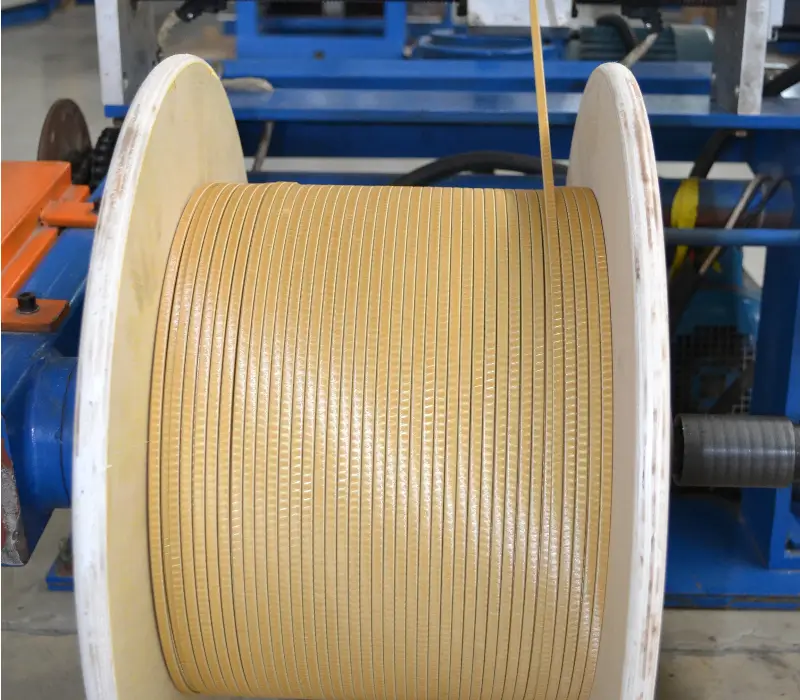
Key Functions of Fiberglass Covered Wire in Aerospace Applications
Glass-fiber-covered magnet wire performs critical multifunctional roles in aerospace equipment: extreme-environment insulation, mechanical reinforcement, vibration and shock resistance, resistance to aviation fluids, low outgassing in vacuum, radiation resistance, atomic oxygen resistance, and integration with intelligent monitoring systems.
Regarding the insulating core function, the high voltage, high frequency, and high power density of aerospace equipment impose stringent requirements on insulation:
- Turn-to-turn insulation: Insulation between adjacent conductors; fiberglass coating (single-layer, 0.10–0.30 mm) with breakdown voltage of 170–540 V (MW 41-C)
- Layer-to-layer insulation: Insulation between different layers within the same winding; fiberglass coating (double-layer) or multi-layer composite
- Phase-to-phase insulation: Insulation between windings of different phases; fiberglass + insulating sleeve + end ring
- Ground insulation: Insulation between the winding and the core or housing; fiberglass + insulating varnish + impregnating resin
- Main insulation (high-voltage aerospace motors/generators): Fiberglass + mica tape + impregnating resin
Dielectric strength of glass fiber coating (in air): ≥10 kV/mm (single layer), ≥20 kV/mm (double layer). The breakdown voltage of the glass fiber + enamel combination complies with NEMA MW 41-C (Class 155°C glass-fiber-covered enameled round copper wire).
Regarding high-temperature resistance—the core functional attribute—glass-fiber-covered magnet wire is selected for aerospace equipment primarily due to its superior temperature resistance.
- Continuous operating temperature: 155–260 °C (depending on insulation enamel/resin type)
- Short-term overload capability: Insulation temperature rise ≤ 15 K under 1.2–1.5× overload for several hours
- Short-circuit thermal resistance: 300 °C (copper) / 260 °C (aluminum) for 3–10 seconds
- Softening breakdown temperature: 330–350 °C for glass fiber + enamel (AIW) composite insulation
- Flame retardancy: Glass-fiber-covered wire rated UL 94 V-0 (self-extinguishing, low smoke, low toxicity)
Glass-fiber-covered magnet wire temperature ratings:
– 155 °C (Class F): glass fiber + PEW/EIW enamel (per MW 41-C/MW 51-C)
– 180 °C (Class H): glass fiber + polyester-glass composite (per MW 45-C/MW 51-C)
– 200 °C: glass fiber + silicone enamel (per MW 43-C/MW 47-C)
– 220 °C: glass fiber + AIW enamel (per MW 84-C)
– 240 °C: glass fiber + polyimide enamel (per MW 20-C)
Regarding mechanical reinforcement, the extreme mechanical environments encountered by aerospace equipment—vibration of 20–50 g, shock of 100–500 g, and steady-state acceleration of 20–50 g—impose exceptionally high requirements on the mechanical performance of windings.
- Vibration resistance: The high tensile strength (2000–3500 MPa) of glass fiber provides exceptional vibration resistance.
- Impact resistance: The combination of glass fiber and impregnating resin withstands high-g impacts of 100–500 g (ejection, crash, combat damage).
- Acceleration resistance: Glass-fiber-covered wire withstands sustained acceleration of 50 g (aircraft maneuvering, rocket launch).
- Short-circuit electromagnetic force resistance: Withstands transformer short-circuit electromagnetic forces of 10–50 kA/1 s without damage.
- Flexibility: Glass-fiber-covered wire exhibits excellent bendability with a small bending radius (2–5d).
- Abrasion resistance: The combination of glass fiber and enamel coating provides abrasion resistance (tested per IEC 60851 abrasion test).
Mechanical properties of fiberglass-covered magnet wire (per MW 41-C):
– Tensile strength: fiberglass 2000–3500 MPa
– Elongation (with fiberglass covering): 35% for 4/0–1/0 AWG, 30% for 1–8 AWG, 20% for 9–15 AWG, 15% for 16–21 AWG, and 20% for 22–28 AWG (per Table 2 of MW 41-C)
– Springback: ≤5° for bare fiberglass-covered wire in sizes 4/0–13 AWG; ≤5.5° for enameled fiberglass-covered wire in sizes 4–13 AWG
Regarding resistance to aerospace fluids, aerospace equipment comes into contact with various specialized fluids:
- Aviation fuels: Jet A, Jet A-1, JP-8, JP-5, RP-3 (glass fiber + AIW coating oil-resistant)
- Hydraulic fluids: Skydrol LD-4 (phosphate ester), Skydrol 500B, MIL-H-5606 (mineral oil)
- Lubricants: MIL-L-7808, MIL-L-23699 (synthetic ester-based aircraft lubricating oil)
- De-icing fluids: Ethylene glycol/propylene glycol
- Cleaners: Isopropyl alcohol, acetone, gasoline
- Coolants: Ethylene glycol/water mixture
Fluid resistance of glass fiber + impregnating resin (polyester/epoxy/silicone/AIW):
– Glass fiber + AIW coating: resistant to Skydrol LD-4 (aviation hydraulic fluid) for >1000 hours
– Glass fiber + silicone organic coating: resistant to lubricating oil/fuel for 100–1000 hours
– Glass fiber + epoxy impregnation: resistant to fuel/hydraulic fluid for 500–2000 hours
Regarding vacuum outgassing performance, spacecraft impose stringent material outgassing requirements under vacuum conditions (NASA ASTM E595):
- TML (Total Mass Loss): ≤1%
- CVCM (Condensable Volatile Content): ≤0.1%
- Fiberglass (E-glass/S-glass/D-glass): TML ≤0.5%, CVCM ≤0.05%
- Fiberglass + High-Purity Impregnating Resin: TML ≤0.8%, CVCM ≤0.08%
- Fiberglass + Silicone Organic Coating: TML ≤1.0%, CVCM ≤0.10%
Impact of outgassing in vacuum on spacecraft:
– Contamination of optical components: condensable volatile compounds deposit onto lenses and sensors
– Contamination of solar cells: reduction in photovoltaic conversion efficiency
– Mass loss: affects spacecraft mass balance
– Cold welding formation: condensable volatile compounds may cause cold welding under high vacuum conditions
Regarding radiation resistance, spacecraft operating in the space radiation environment impose stringent requirements on material radiation resistance:
- Total ionizing dose (TID): 100–1000 krad(Si) (5–10 years in low Earth orbit)
- Single-event effects (SEE): faults induced by high-energy particles
- Displacement damage: lattice defects
- Ionizing radiation: gamma rays, X-rays, electron irradiation
Radiation resistance of glass-fiber-covered magnet wire:
– E-glass fiber: γ-ray resistance >10⁸ rad
– S-glass fiber: γ-ray resistance >10⁹ rad
– Glass fiber + AIW enamel: γ-ray resistance >10⁷ rad (combined with AIW radiation resistance)
– Glass fiber + polyimide enamel: γ-ray resistance >10⁸ rad
– Glass fiber + impregnating resin: γ-ray resistance >10⁷ rad (depending on resin type)
Atomic oxygen resistance (specific to low Earth orbit, LEO):
- Atomic oxygen flux: 10¹⁵ atoms/cm²/s at 400 km altitude
- Glass fiber + AIW coating: atomic oxygen resistant (AIW dense structure)
- Glass fiber + Kapton: atomic oxygen resistant
- Glass fiber + silicone organic coating: atomic oxygen resistant (moderate)
- Glass fiber + epoxy: atomic oxygen resistant (weak)
- Addition of nano-SiO₂/TiO₂: significantly enhances atomic oxygen resistance
Regarding flame resistance/smoke suppression/toxicity reduction (FST), aerospace materials must meet stringent flame-retardant requirements (OSU 65/65, FAA 25.853):
- Heat Release Rate (HRR): Peak ≤65 kW/m², Average ≤65 kW/m² (OSU 65/65, within 2 minutes)
- Smoke Density (Ds): ≤200 (within 4 minutes)
- Toxicity Index: Low toxicity
- Self-extinguishing time: ≤10 seconds
- Glass fiber + AIW enamel coating: OSU 65/65 rating (self-extinguishing, low smoke, low toxicity)
Regarding intelligent monitoring integration, the high-reliability requirements of aerospace equipment mandate the integration of intelligent monitoring functionality:
- Optical fiber temperature sensor: Distributed optical fiber (Brillouin/Raman scattering) for real-time winding temperature monitoring
- PD sensor: Built-in high-frequency current transformer (HFCT) or UHF sensor
- Vibration sensor: Built-in piezoelectric accelerometer
- Health monitoring system: Real-time winding condition monitoring and fault prediction
- Digital twin: AI-based winding condition prediction
Comparison of Fiberglass Covered Wire with Other Insulation Materials
Glass-fiber-covered magnet wire is one of the commonly used winding insulation materials in aerospace equipment, offering distinct advantages over other insulation materials—such as pure enameled wire, paper-covered wire, and composite insulation materials—in terms of temperature resistance, mechanical properties, electrical performance, chemical resistance, vacuum compatibility, radiation resistance, flame retardancy, and weight reduction.
Fiberglass-Clad Wire (FGW) vs. Enamel-Coated Wire (EWW):
| Item | Glass-Fiber-Insulated Wire | Enamelled Wire |
|---|---|---|
| Temperature Rating | 155–260 °C | 105–240 °C (Polyimide highest) |
| Mechanical Strength | High (glass-fiber reinforced) | Medium (enamel coating) |
| Vibration Resistance | Excellent | Medium |
| Impact Resistance | Excellent | Medium |
| Dielectric Strength | Medium–High | High (uniform enamel coating) |
| Breakdown Voltage | 170–540 V (single-layer, NEMA MW 41-C) | 2000–8000 V (enamel coating) |
| Oil Resistance | Medium–High (dependent on enamel type) | Medium (enamel degraded by Skydrol) |
| Skydrol Resistance | Excellent (AIW coating) | Poor–Medium |
| Outgassing in Vacuum | Low (glass fiber + resin) | Medium (enamel coating) |
| Radiation Resistance | Excellent (glass fiber) | Medium–High (dependent on enamel type) |
| Atomic Oxygen Resistance | Medium–High (dependent on enamel type) | Medium (dependent on enamel type) |
| Flame, Smoke, and Toxicity (FST) Resistance | Excellent (glass fiber + AIW) | Poor–Medium (dependent on enamel type) |
| Weight | Heavier (glass fiber density: 2.5 g/cm³) | Lighter (thin enamel coating) |
| Process Maturity | Mature (aerospace applications for >60 years) | Mature |
| Cost | High (glass fiber + impregnation) | Low–Medium |
Fiberglass-Clad Wire (FGW) vs. Paper-Clad Wire (PCW):
| Item | Glass-Fiber-Insulated Wire | Paper-Insulated Wire |
|---|---|---|
| Temperature Rating | 155–260 °C | 105–220 °C |
| Mechanical Strength | High (glass-fiber reinforced) | Medium (paper-based) |
| Vibration Resistance | Excellent | Medium–High (crepe paper) |
| Impact Resistance | Excellent | Medium |
| Dielectric Strength (oil-immersed) | In air | Oil-immersed ≥30 kV/mm (kraft paper) |
| Vacuum Outgassing | Low | Medium (moisture absorption ≤8%) |
| Radiation Resistance | Excellent | Medium–High (kraft paper) |
| Atomic Oxygen Resistance | Medium–High | Weak–Medium |
| Flame, Smoke, and Toxicity (FST) Resistance | Excellent | Excellent (Nomex 410) |
| Weight | Relatively heavy | Relatively light |
| Process Maturity | Mature | Mature |
| Cost | High | Medium–High |
Fiberglass-Clad Wire (FGW) vs. Polyimide Enamel-Coated Wire (PI EWW):
| Item | Glass-Fiber-Insulated Wire | Polyimide (PI) Enamelled Wire |
|---|---|---|
| Temperature Rating | 155–260 °C | 240–260 °C |
| Dielectric Strength | Medium–High | Extremely High (≥200 kV/mm) |
| Radiation Resistance | Excellent | Excellent |
| Flame, Smoke, and Toxicity (FST) Resistance | Excellent | Excellent (PI is inherently flame-retardant) |
| Skydrol® Resistance | Excellent | Excellent (PI is resistant to Skydrol®) |
| Outgassing in Vacuum | Low | Low (PI exhibits extremely low outgassing rate in vacuum) |
| Atomic Oxygen Resistance | Excellent (glass fiber) | Poor (PI degrades upon atomic oxygen exposure) |
| Weight | Relatively Heavy | Light |
| Process Maturity | Mature | Mature |
| Cost | Medium–High | High |
Fiberglass-covered wire (FGW) vs. fiberglass-paper-covered wire (FGPCW):
- Glass-fiber-covered wire: glass fiber + enamel coating (outer layer), simple structure
- Glass-fiber-paper-covered wire: glass fiber + paper-based insulation (DMD/NMN) composite
- Glass-fiber-paper-covered wire exhibits high dielectric strength and superior short-circuit resistance; glass-fiber-covered wire offers superior mechanical strength
- Glass-fiber-covered wire is suitable for turn-to-turn and layer-to-layer winding insulation; glass-fiber-paper-covered wire is suitable for main insulation and high-voltage windings
Unique Advantages of Glass-Fiber-Insulated Magnet Wire:
- Vibration and impact resistance: The exceptional mechanical properties of fiberglass (tensile strength 2000–3500 MPa) are unmatched by enameled wire or paper-wrapped wire.
- Skydrol hydraulic fluid resistance: Fiberglass + AIW coating exhibits resistance to phosphate ester hydraulic fluids (a critical aerospace requirement).
- Atomic oxygen resistance: Fiberglass inherently possesses atomic oxygen resistance, a property difficult to replicate with other insulation materials.
- Flame, smoke, and toxicity (FST) resistance: Fiberglass + AIW coating meets stringent FST requirements per OSU 65/65 and FAA 25.853.
- Temperature rating 200–240 °C: Comparable to polyimide (PI) enameled wire, yet superior in mechanical performance.
- Proven manufacturing process: Fiberglass-wrapped wire has been applied in aerospace equipment for over 60 years (since the 1960s).
Disadvantages of glass-fiber-covered magnet wire:
- Weight: Glass fiber density of 2.5 g/cm³ is heavier than enamel coating.
- Dielectric strength (single-layer): Lower than that of enamel coating; multi-layer or multi-layer structure required.
- Cost: Higher cost associated with glass fiber and impregnation process.
- Processability: Larger bending radius after glass fiber wrapping.
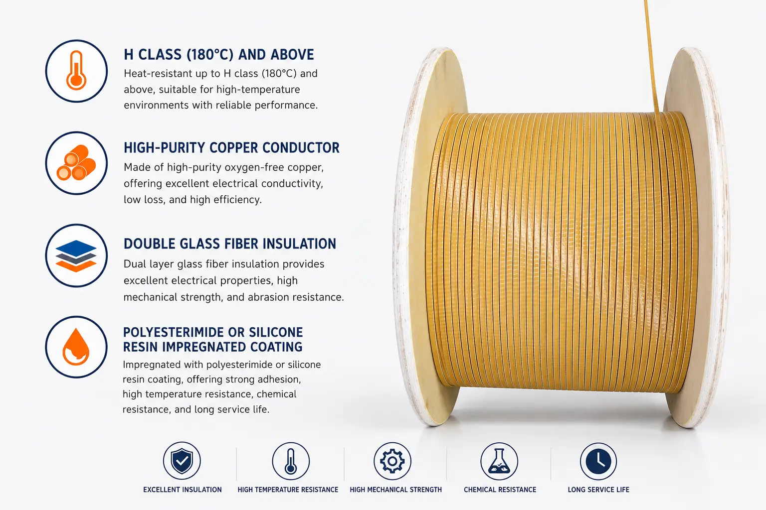
Types and Specifications of Fiberglass Covered Wire
Aerospace-grade glass-fiber-covered magnet wire is classified according to insulation material, wrapping configuration, conductor type, thermal class, and dimensions.
By insulation material type (by thermal class):
- 155°C (Class F): Glass fiber + polyester enamel (PEW) coating
- Standards: NEMA MW 41-C (round copper enameled wire with glass fiber covering), MW 42-C (rectangular)
- Dielectric strength: ≥10 kV/mm
- Industrial applications: Standard aerospace motors, transformers
- 180°C (Class H): Glass fiber + polyester-imide enamel (EIW) coating
- Standards: NEMA MW 45-C (round copper enameled wire with polyester-glass fiber overcoat), MW 46-C (rectangular)
- Dielectric strength: ≥12 kV/mm
- Industrial applications: High-efficiency aerospace motors, traction transformers
- 180°C (Class H): Glass fiber + polyester-glass fiber + high-temperature organic enamel
- Standards: NEMA MW 51-C (round copper wire with polyester-glass fiber and high-temperature organic enamel), MW 52-C (rectangular)
- Dielectric strength: ≥12 kV/mm
- Industrial applications: High-temperature aerospace motors, military special-purpose equipment
- 200°C: Glass fiber + organosilicon enamel coating
- Standards: NEMA MW 43-C (round copper magnet wire with glass fiber braid and organosilicon enamel), MW 44-C (rectangular)
- Dielectric strength: ≥15 kV/mm
- Industrial applications: High-temperature aerospace motors, rocket power supplies
- 200°C: Glass fiber + polyester-glass fiber + silicone organic enamel
- Standards: NEMA MW 47-C (polyester-glass fiber-silicone organic enamel coated round copper wire), MW 48-C (rectangular)
- Dielectric strength: ≥15 kV/mm
- Industrial applications: Extreme high-temperature aerospace motors, deep-space probes
- 220°C (R/C): Glass fiber + polyamide-imide enamel (AIW) coating
- Standard: NEMA MW 84-C (Polyamide-imide 220°C round copper magnet wire) + glass fiber overwrap
- Softening breakdown temperature: 330–350°C
- Industrial applications: High-temperature aerospace motors, rockets, missiles
- 240°C: Glass fiber + polyimide (PI) enamel coating
- Standard: NEMA MW 20-C (Polyimide 240°C round copper magnet wire) + glass fiber overwrap
- Dielectric strength: ≥200 kV/mm
- Industrial applications: Ultra-high-temperature aerospace motors, deep-space probes, spacecraft
By glass fiber type (by substrate):
- E-glass (Electrical Glass):
- Composition: SiO₂ 54%, CaO 17%, Al₂O₃ 14%, B₂O₃ 10%
- Density: 2.55–2.60 g/cm³
- Tensile Strength: 2000–3500 MPa
- Dielectric Strength: ≥10 kV/mm
- Application: General-purpose aerospace (90%+ market share)
- S-Glass (High-Strength Glass):
- Composition: SiO₂ 64%, Al₂O₃ 25%, MgO 10%
- Density: 2.48–2.55 g/cm³
- Tensile Strength: 3500–4800 MPa
- Dielectric Strength: ≥10 kV/mm
- Applications: High-performance aerospace, missile, and rocket systems
- D-Glass (Dielectric Glass):
- Composition: High SiO₂ (>70%), low B₂O₃
- Dielectric strength: ≥15 kV/mm
- Dielectric constant: ≤4.0
- Application: High-dielectric, high-frequency aerospace
- Basalt Fiber:
- Composition: Natural basalt (SiO₂ + Al₂O₃ + FeO)
- Density: 2.65–2.80 g/cm³
- Tensile Strength: 3000–4500 MPa
- Temperature Resistance: –260 °C to +700 °C
- Dielectric Strength: ≥10 kV/mm
- Application: Emerging aerospace material
By wrapping configuration:
- Overlapping Wrap: 50% overlap, single-layer or double-layer
- Butt Wrap: no overlap
- Half-Lap Wrap: 50% overlap per layer, multi-layer stacking (2–4 layers)
- Multi-Lap Wrap: multi-layer stacking of fiberglass yarn (2–3 layers), total thickness 0.20–0.80 mm
- Helical Wrap: helical configuration, winding angle 5–15°
- Single Wrap: single-layer coverage, 50–65% overlap
- Double Wrap: double-layer coverage, staggered lap positions
By conductor type:
- Round wire: diameter 0.04–7.00 mm (fine wire: 0.04–0.50 mm; medium wire: 0.50–2.50 mm; heavy wire: 2.50–7.00 mm)
- Rectangular wire: width 2.00–16.00 mm × thickness 0.80–5.60 mm (within IEC 60317-0-8 range)
- Transposed cable (CTC): multiple enameled rectangular copper wires assembled, transposed, and overall glass fiber wrapped
- Enameled base coating + glass fiber wrapping (dual insulation)
- Glass fiber wrapping for single or stranded wires
- Glass fiber wrapping for high-strength copper alloys (Cu-Ag, Cu-Cr-Zr) (special applications)
According to specifications (IEC 60317 / NEMA MW 1000):
- Round copper wire / round aluminum wire: diameter 0.04–7.00 mm (PT4–PT200 spools)
- Rectangular copper wire / rectangular aluminum wire: width 2.00–16.00 mm × thickness 0.80–5.60 mm
- Enamel coating grades: Grade 1 (thin), Grade 2 (medium), Grade 3 (heavy)
- Glass fiber covering: single-layer (0.10–0.30 mm), double-layer (0.20–0.60 mm)
NEMA MW 1000-2018 Glass-Fiber-Insulated Wire Standard (Aerospace Mainstream):
- MW 41-C (Round, 155°C, Glass-Fiber-Overcoated Enamelled Wire): Glass Fiber + Polyester Enamel
- MW 42-C (Rectangular, 155°C, Glass-Fiber-Overcoated Enamelled Wire)
- MW 43-C (Round, 200°C, Glass-Fiber-Overcoated Silicone Organic Enamelled Wire)
- MW 44-C (Rectangular, 200°C, Glass-Fiber-Overcoated Silicone Organic Enamelled Wire)
- MW 45-C (Round, 155°C, Polyester-Glass-Fiber-Overcoated Enamelled Wire)
- MW 46-C (Rectangular, 155°C, Polyester-Glass-Fiber-Overcoated Enamelled Wire)
- MW 47-C (Round, 200°C, Polyester-Glass-Fiber-Overcoated Silicone Organic Enamelled Wire)
- MW 48-C (Rectangular, 200°C, Polyester-Glass-Fiber-Overcoated Silicone Organic Enamelled Wire)
- MW 50-C (Round, 180°C, Glass-Fiber-Overcoated High-Temperature Organic Enamelled Wire)
- MW 51-C (Round, 180°C, Polyester-Glass-Fiber-Overcoated High-Temperature Organic Enamelled Wire)
- MW 52-C (Rectangular, 180°C, Glass-Fiber-Overcoated High-Temperature Organic Enamelled Wire)
- MW 53-C (Rectangular, 180°C, Polyester-Glass-Fiber-Overcoated High-Temperature Organic Enamelled Wire)
- MW 54-C (Round, 155°C, Double-Layer Polyester-Glass-Fiber-Overcoated Enamelled Wire)
- MW 84-C (Round, 220°C, Polyamide-imide Enamelled Wire) + Glass-Fiber Overcoat
- MW 20-C (Round, 240°C, Polyimide Enamelled Wire) + Glass-Fiber Overcoat
Manufacturing Process and Quality Control of Fiberglass Covered Wire
The manufacturing process for glass-fiber-covered magnet wire for aerospace applications demands higher precision, stricter quality control, and enhanced traceability compared to that for general industrial glass-fiber-covered magnet wire.
Manufacturing Process of Round Glass-Fiber-Insulated Magnet Wire:
- Conductor Preparation: Round copper rod (Cu ≥99.95%, C10100, C10200, C11000) or round aluminum rod (Al ≥99.5%) drawn through multiple dies to target diameter.
- Continuous Annealing: Copper conductor annealed at 600–650 °C (to restore flexibility and eliminate work hardening).
- Surface Cleaning: Acid–alkali cleaning to remove oxide layers and lubricant residues.
- In-line Defect Detection: Laser micrometer and CCD vision system (100% inspection of diameter, ovality, and defects).
- Enamel Coating (Base Insulation Layer; PEW/EIW/AIW/PI selected per thermal class):
– Coating method: Die coating or roller coating.
– Number of coating passes: 1–3 for single-layer; 4–8 for double-layer.
– Baking temperature: 150–200 °C; baking time: 4–12 hours. - Glass Fiber Overwrap: E-glass or S-glass yarn helically wound.
– Glass yarn specification: ECG 37.5, ECG 75, ECG 150 (selected according to conductor diameter).
– Winding tension: Precisely controlled (5–30 N, to prevent glass fiber breakage).
– Winding angle: 5–15° (overlap ratio: 50–65%).
– Winding speed: 30–200 m/min. - Multi-layer Glass Fiber Overwrap: 2–3 layers of glass fiber (staggered lap positions).
- Impregnation Treatment: Immersion in insulating varnish/resin (polyester, polyester-imide, epoxy, silicone resin, AIW, PI).
- Baking and Curing: Hot-air circulation oven (150–250 °C, 4–16 hours).
- Vacuum Pressure Impregnation (VPI):
- Vacuum level: ≤100 Pa.
- Pressure: 0.5–1.0 MPa.
- Impregnation time: 2–8 hours.
- Baking and curing: 150–200 °C, 8–24 hours.
- In-line Partial Discharge (PD) Testing: HFCT-based PD detection.
- In-line Dielectric Withstand Testing: 100% spark testing (AC 1–5 kV).
- In-line Dielectric Testing: 100% breakdown voltage testing or sampling.
- Reeling: Automatic reel-up machine (reel dimensions compliant with IEC 60264-3).
- Full-process Traceability: MES system, batch coding, SPC control.
Flat glass-fiber-covered magnet wire manufacturing process:
- Conductor preparation: Flat copper wire / flat aluminum wire (produced by rolling round wire or using shaped billets)
- Edge rounding: R 0.5–1.0 mm (to prevent stress concentration)
- Continuous annealing: Copper at 600–650 °C / aluminum at 350–450 °C
- Surface cleaning: Removal of oxide layer and contaminants
- Leveling: Rolling leveling (flatness ≤ 0.10 mm/m)
- Enamel coating: PEW/EIW/AIW/PI selected according to thermal class
- Glass fiber wrapping: Glass fiber yarn winding (same process as for round wire)
- Multi-layer glass fiber wrapping
- Impregnation treatment
- Baking and curing
- Vacuum Pressure Impregnation (VPI)
- Online partial discharge (PD) testing + spark testing
- Reeling
Transposition Cable (CTC) with Glass Fiber Wrapping Manufacturing Process:
- Single enameled rectangular copper wire: 1–3 mm wide × 3–8 mm thick
- Multi-strand transposition: 7–31 enameled rectangular copper wires laid side by side
- Transposed braiding: transposition pattern (transposition every pitch)
- Overall glass fiber wrapping: complete wrapping with glass fiber yarn
- Impregnation treatment + baking cure
- Vacuum pressure impregnation (VPI)
- Reeling
Quality Control of Glass-Fiber-Insulated Magnet Wire for Aerospace Applications:
- In-line inspection equipment:
- Laser diameter gauge (diameter tolerance ±0.01 mm)
- In-line partial discharge (PD) detection (HFCT sensor)
- Spark test (AC 1–5 kV, 100% in-line)
- Tension monitoring (glass fiber wrapping tension: 5–30 N)
- CCD vision system (defect, incomplete wrapping, and damage detection)
- In-line thickness measurement (X-ray, laser)
- VPI impregnation parameters (vacuum level, temperature, pressure)
- Vacuum outgassing test (NASA ASTM E595, for special applications)
- Radiation resistance testing (γ-ray, for special applications)
- Sampling Inspection (Aerospace-Grade Rigorous Requirements):
- Dielectric Breakdown Voltage: Sampling Test (≥170 V for single-layer glass fiber + enamel coating, NEMA MW 41-C)
- Dielectric Strength: Sampling Test
- Elongation: Sampling Test (annealed copper ≥30%, per Table 2 of MW 41-C)
- Conductor Resistivity: Cu ≤0.01724 Ω·mm²/m
- Outgassing in Vacuum: TML ≤1%, CVCM ≤0.1% (NASA ASTM E595)
- Radiation Resistance: γ-ray exposure of 10⁷–10⁹ rad (application-dependent)
- Skydrol Resistance: 1000-hour Skydrol LD-4 resistance test
- Flame Resistance: OSU 65/65 and FAA 25.853 tests
- Vibration Resistance: RTCA DO-160 and MIL-STD-810 vibration tests
- Shock Resistance: MIL-STD-810 shock test
- Salt Spray Resistance: 96–1000 hours (ASTM B117, MIL-STD-810)
- Fungal Resistance: MIL-STD-810 fungal test
- Quality Management Systems:
- AS9100D (Aerospace Quality Management System)
- ISO 9001 (Fundamental Quality Management System)
- Nadcap (Special Process Certification: Winding, Impregnation, Baking)
- PPAP (Production Part Approval Process)
- APQP (Advanced Product Quality Planning)
- FMEA (Failure Mode and Effects Analysis)
- SPC (Statistical Process Control)
- MES System (End-to-End Traceability)
- AS6081 (Counterfeit Electronic Parts Detection and Avoidance, adopted by component supply chains)
- CCAP (Counterfeit Components Avoidance Program)
- Critical process parameters:
- Annealing temperature: copper 600–650 °C / aluminum 350–450 °C
- Glass fiber wrapping tension: 5–30 N
- Glass fiber wrapping speed: 30–200 m/min
- Enamel curing temperature: 150–200 °C
- Enamel curing time: 4–12 hours
- VPI vacuum level: ≤100 Pa
- VPI pressure: 0.5–1.0 MPa
- VPI impregnation time: 2–8 hours
- VPI bake-cure: 150–250 °C, 8–24 hours
- Spark test voltage: AC 1–5 kV
- Online partial discharge (PD) threshold: ≤5 pC
Applications in Aircraft Motors
Aerospace motors are core power components of aerospace equipment, including integrated drive generators (IDG), auxiliary power unit (APU) motors, electro-mechanical actuators (EMA), electro-mechanical brakes (EMB), fuel pump motors, hydraulic pump motors, and environmental control system (ECS) motors. The extreme operating conditions encountered by aerospace motors—such as high altitude (>10,000 m), low atmospheric pressure, wide temperature range (–65 °C to +260 °C), and resistance to vibration and shock—impose exceptionally stringent requirements on winding insulation.
Aerospace starter-generators (IDG, Integrated Drive Generator):
- Capacity: 30–300 kVA (typical for civil aircraft: 90–150 kVA)
- Frequency: 400 Hz (civil aviation standard)
- Rotational speed: 12,000–24,000 rpm
- Typical applications: Boeing 737/777/787, Airbus A320/A330/A350
- Features: Direct drive by engine (gearbox transmission), high-altitude operation
- Recommended paper-wrapped wire:
- Stator winding: Enameled rectangular wire (PEW/EIW) + double-layer glass fiber wrapping + vacuum pressure impregnation (VPI)
- Rotor winding: Glass fiber–wrapped enameled rectangular wire + double-layer glass fiber wrapping + high-strength impregnation
- End winding tie-down: Glass fiber + impregnating resin
- Slot insulation: NMN + glass fiber
Auxiliary Power Unit (APU) motors for aviation applications:
- Capacity: 10–50 kVA
- Application: APU start/generation (powering onboard equipment when the main engine is shut down)
- Characteristics: High-altitude operation, vibration, thermal shock
- Recommended paper-wrapped wire:
- Enameled rectangular wire (PEW/EIW) + double-layer glass fiber wrapping + VPI impregnation
- High-temperature insulation: Glass fiber + AIW enamel coating (220 °C continuous rating)
Electro-Mechanical Actuator (EMA) motors for aerospace applications:
- Capacity: 1–10 kW
- Features: Frequent start/stop cycles, braking capability, wide operating temperature range, high reliability
- Applications: Aircraft flaps, slats, rudders, elevons
- Recommended paper-wrapped wire configurations:
- Enamelled round wire (PEW/EIW) + fiberglass overwrap + VPI impregnation
- High power density: Fiberglass + AIW enamel coating + high-strength impregnation
Electro-Mechanical Brake (EMB) Motors for Aerospace Applications:
- Capacity: 5–30 kW
- Features: Frequent braking, high torque, wide operating temperature range
- Application: Aircraft landing gear brakes
- Recommended paper-wrapped wire:
- Enameled rectangular wire (high-strength copper alloy Cu–Ag) + glass fiber wrapping + VPI impregnation
- High overload capability: Glass fiber + AIW enamel coating + high-strength impregnation
Aircraft fuel pump motors:
- Capacity: 1–20 kW
- Features: Aviation fuel resistance (JP-8, Jet A), frequent start-stop operation
- Recommended paper-wrapped wire:
- Enamelled round wire + glass fiber + AIW enamel coating (resistant to Skydrol hydraulic fluid and aviation fuel)
- Oil-resistant impregnating resin
Aerospace hydraulic pump motors:
- Capacity: 5–50 kW
- Features: Resistant to Skydrol LD-4 phosphate ester hydraulic fluid
- Recommended paper-covered wire:
- Enamelled round wire + fiberglass + AIW enamel coating (Skydrol-resistant)
- Impregnating resin resistant to phosphate esters
Aerospace Environmental Control System (ECS) motors:
- Capacity: 0.5–10 kW
- Applications: Cabin air conditioning, boosting, air recirculation
- Features: Wide operating temperature range (–55 °C to +85 °C), medium power
- Recommended paper-wrapped wire:
- Enamelled round wire + double-layer glass fiber wrapping + VPI impregnation
Unmanned Aerial Vehicle (UAV/Drone) Motors:
- Capacity: 0.1–100 kW
- Type: Permanent Magnet Synchronous Motor (BLDC/PMSM), Brushless DC Motor
- Features: Ultra-high power density (5–10 kW/kg), lightweight, high efficiency
- Voltage: 28 V, 48 V, 100 V, 270 V, 540 V DC
- Speed: 10,000–50,000 rpm (typical for UAV motors: 30,000 rpm)
- Recommended Paper-Insulated Wire Solutions:
- Enamelled Round Wire + Fiberglass Tape Wrap + Vacuum Pressure Impregnation (VPI)
- High-Strength Enamel Coating: Fiberglass Tape + AIW Enamel + Vacuum Pressure Impregnation
- High Slot Fill Factor: Fiberglass Tape + Flat Copper Wire + High-Strength Impregnation
- Lightweighting: Aluminum Wire + Fiberglass Tape + Impregnation (for selected applications)
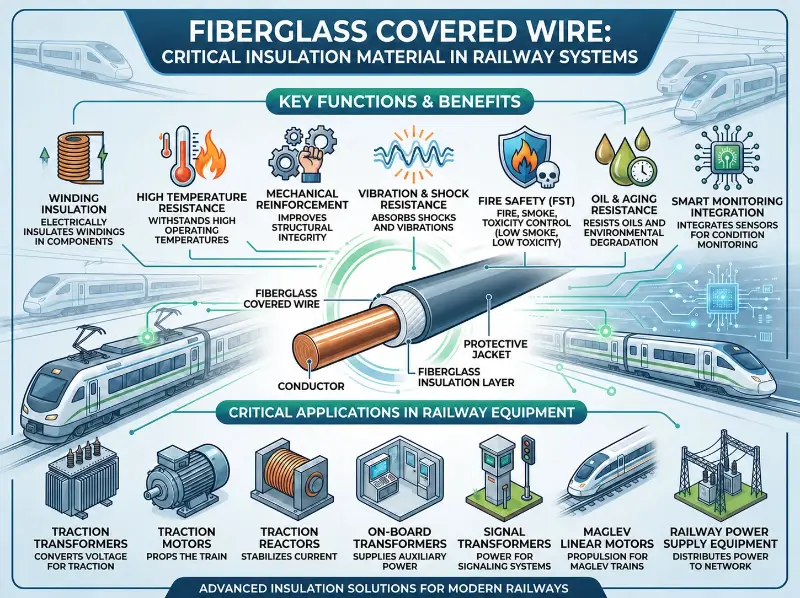
Applications in Spacecraft Power Systems
The spacecraft power system is one of the most critical subsystems of a spacecraft, responsible for delivering stable electrical power to all payloads and platform electronics. It comprises solar arrays, energy storage batteries (lithium-ion/nickel-hydrogen/ultracapacitors), a power control and distribution unit (PCDU), power distribution systems, converters/inverters, and other components. Spacecraft operate in extreme environments—including vacuum, radiation, thermal cycling, and atomic oxygen—imposing stringent requirements on winding insulation properties, particularly outgassing in vacuum, radiation resistance, atomic oxygen resistance, and thermal cycling resistance.
Satellite power bus applications:
- Voltage ratings: 28 V (low power), 42 V (medium power), 100 V / 120 V (high-voltage bus)
- Types: Direct Energy Transfer (DET), Peak Power Tracking (PPT), Maximum Power Point Tracking (MPPT)
- Key components: Solar array, Power Control and Distribution Unit (PCDU), energy storage battery pack
- Glass-fiber-covered magnet wire applications:
- Solar array driver: Enamelled round wire + glass fiber covering + vacuum pressure impregnation (VPI)
- Energy storage battery pack (BMS): Enamelled round wire + glass fiber covering
- PCDU transformer: Enamelled rectangular wire + glass fiber covering + vacuum impregnation (outgassing prevention)
- Bus filter: Enamelled round wire + glass fiber covering
Satellite solar array applications:
- Types: Monocrystalline silicon, polycrystalline silicon, gallium arsenide (GaAs), copper indium gallium selenide (CIGS)
- Array types: Fixed, deployable (folding + deployment mechanism)
- Glass-fiber-covered magnet wire applications:
- Solar array deployment mechanism motor: Enamelled round wire + glass fiber covering + vacuum pressure impregnation (VPI)
- Solar array drive motor: Enamelled round wire + glass fiber covering + VPI
- Solar array temperature control: Glass fiber + AIW enamel coating (capable of withstanding thermal cycling from –180 °C to +150 °C)
Satellite energy storage battery packs:
- Type: Lithium-ion (Li-ion) batteries, nickel-metal hydride (Ni-MH) batteries, supercapacitors
- Applications: Low Earth Orbit (LEO) satellites (15–30% depth of discharge, DOD), Geostationary Earth Orbit (GEO) satellites (80% DOD)
- Glass-fiber insulated wire applications:
- Battery management systems (BMS): enameled round wire + glass fiber overcoat
- Battery pack thermal control: glass fiber + AIW enamel coating
Satellite Power Control Unit (PCDU):
- Capacity: 1–30 kW (LEO: 1–10 kW; GEO: 5–30 kW)
- Key components: DC/DC converter, MPPT controller, battery charger, busbar filter
- Fiberglass-covered magnet wire applications:
- DC/DC converter transformer: Enameled rectangular wire + fiberglass covering + vacuum impregnation
- Busbar filter: Enameled round wire + fiberglass covering + vacuum impregnation
- Busbar reactor: Enameled round wire + fiberglass covering + vacuum impregnation
- Critical requirements: Vacuum outgassing TML ≤1%, CVCM ≤0.1% (NASA ASTM E595)
Rocket power supply systems:
- Type: Chemical battery (primary), fuel cell (SpaceX), solar cell (satellite)
- Capacity: 100 W–50 kW
- Key components: Battery pack, power distribution system, converter
- Glass-fiber-covered magnet wire applications:
- Battery management system (BMS): Enamelled round wire + glass fiber covering
- DC/DC converter: Enamelled rectangular wire + glass fiber covering
- Power distribution filter: Enamelled round wire + glass fiber covering
- Vibration resistance (launch phase: 10–50 g): Glass fiber + AIW enamel coating + high-strength impregnation
- Shock resistance (explosive bolts, separation mechanisms): Glass fiber + high-strength impregnation
Space station power system:
- Type: Solar array + energy storage battery pack
- Capacity: 75–120 kW (ISS, Tianggong)
- Glass-fiber-covered magnet wire applications:
- Large PCDU: Glass-fiber-covered rectangular enameled wire + VPI
- Solar array drive motor: Glass fiber + AIW enamel coating
- Busbar transformer: Glass fiber + vacuum impregnation
- Long-term stability: 10–30 years operation in space
Power supply for deep-space probes:
- Type: Solar array (near-Earth), RTG (deep-space)
- Glass-fiber insulated wire applications:
- Long-life PCDU: Glass fiber + AIW insulation + vacuum impregnation
- High radiation resistance: Glass fiber + PI insulation + vacuum impregnation
- Thermal cycling resistance: Glass fiber + AIW insulation (–180 °C to +150 °C)
Applications in Aircraft Transformers and Reactors
Aircraft transformers, reactors, inductors, and magnetic amplifiers are critical magnetic components in aircraft power systems, signal systems, and control systems. They operate at a fixed frequency of 400 Hz or under variable-frequency conditions, with extremely high requirements for weight, volume, efficiency, and reliability.
Static Inverters for Aviation:
- Input: 28 V DC (small aircraft/drones) / 270 V DC (Boeing 787)
- Output: 115 V / 200 V three-phase 400 Hz AC
- Capacity: 100 VA – 50 kVA
- Frequency: Fixed at 400 Hz
- Glass-fiber insulated magnet wire applications:
- Power transformers: Enameled rectangular wire (PEW/EIW) + glass-fiber overwrap (double-layer) + vacuum pressure impregnation (VPI)
- Output filters: Enameled round wire + glass-fiber overwrap + VPI
- Critical requirements: 400 Hz high-frequency operation, low loss, lightweight design
Regarding aerospace autotransformers:
- Capacity: 100 VA – 20 kVA
- Frequency: 400 Hz
- Glass-fiber-covered wire applications:
- Enamelled round wire + glass fiber covering + vacuum pressure impregnation (VPI)
- Glass fiber + AIW enamel coating (high-temperature aerospace)
Aerospace rectifier transformers:
- Input: 115 V / 200 V, 400 Hz AC
- Output: 28 V DC (small aircraft), 270 V DC (Boeing 787)
- Fiberglass-covered wire applications:
- Enameled round wire + fiberglass overcoat + vacuum pressure impregnation (VPI)
- Rectifier filtering: fiberglass + AIW enamel coating
Aerospace Reactors:
- Input/Output Filters: 400 Hz Aerospace
- Power Rating: 100 VA – 10 kVA
- Fiberglass-Insulated Wire Applications:
- Enamelled Round Wire + Fiberglass Braid + Vacuum Pressure Impregnation (VPI)
- Fiberglass Braid + AIW Enamel Coating (High-Temperature)
Aerospace magnetic amplifiers (Magamp):
- Application: Voltage regulation in aircraft power systems
- Glass-fiber insulated wire applications:
- Enameled round wire + glass fiber wrapping + vacuum pressure impregnation (VPI)
- High-permeability core + glass fiber
Applications in Aerospace and Special Military Equipment
Electrical systems of military special-purpose equipment operate under extreme conditions—including vibration, shock, radiation, temperature extremes, and corrosion—imposing exceptionally high reliability requirements on winding insulation.
Aerospace engine electrical systems:
- Full Authority Digital Engine Control (FADEC)
- Engine sensors (temperature, pressure, vibration, rotational speed)
- Engine starting system
- Glass-fiber-covered magnet wire applications:
- High-temperature engine sensors: glass fiber + AIW enamel (short-term resistance to 200–300 °C)
- High-temperature engine motors: glass fiber + polyimide (PI) enamel (short-term resistance to 240–300 °C)
- Critical requirements: resistance to 50–100 g vibration; short-term resistance to 200–300 °C
Aircraft-mounted radar/electronic warfare systems:
- Type: AESA (Active Electronically Scanned Array), PESA (Passive Electronically Scanned Array)
- Power: 1–50 kW
- Glass-fiber-covered magnet wire applications:
- T/R module power supply: enameled round wire + glass fiber covering
- Beam-steering motor: enameled round wire + glass fiber covering
- Power transformer: glass fiber + AIW enamel coating
Naval aircraft / naval weapons systems:
- Features: Marine salt fog environment resistance; vibration resistance (shipboard takeoff and landing: 50–100 g)
- Glass-fiber-wrapped wire applications:
- Enameled rectangular wire + glass fiber + AIW enamel coating + vacuum pressure impregnation (VPI)
- Salt fog resistance: 1,000 hours (ASTM B117)
- Fungal resistance: 28 days (ASTM G21)
Unmanned Aerial Vehicles (UAVs / Drones):
- Types: Fixed-wing, rotary-wing, vertical take-off and landing (VTOL/eVTOL)
- Fiberglass-covered wire applications:
- Propulsion motors: Enamelled round wire + fiberglass covering + vacuum pressure impregnation (VPI) (high power density: 5–10 kW/kg)
- Actuator motors: Enamelled round wire + fiberglass covering
- Power systems: Fiberglass + AIW enamel coating + vacuum impregnation
Missiles/Rockets:
- Features: Extreme high-g shock resistance (50–500 g), vibration resistance (10–2000 Hz random vibration), and impact resistance (explosive bolt separation, release-induced shock)
- Glass-fiber insulated magnet wire applications:
- Actuator motors: Enameled round wire + glass fiber overwrap + vacuum pressure impregnation (VPI)
- Battery packs: Glass fiber + AIW enamel coating + vacuum impregnation
- High-g shock resistance: Glass fiber + high-strength impregnation (shock resistance up to 10–50 k m/s²)
- Vacuum outgassing: TML ≤ 1%, CVCM ≤ 0.1% (aerospace and missile applications)
Key Performance Requirements and Testing Methods
Key performance requirements for aerospace-grade glass-fiber-covered magnet wire include: electrical properties, mechanical properties, thermal properties, chemical properties, environmental adaptability, reliability, and intelligence.
Electrical properties:
- Dielectric Withstand Voltage (NEMA MW 41-C):
- Single-layer, 4/0–9.5 AWG: ≥170 V
- Single-layer, 10–23.5 AWG: ≥360 V
- Single-layer, 24–30 AWG: ≥225 V
- Double-layer, 4/0–9.5 AWG: ≥315 V
- Double-layer, 10–23.5 AWG: ≥540 V
- Double-layer, 24–30 AWG: ≥400 V
- Note: For glass-fiber-covered wire with an underlying enamel coating, the minimum dielectric withstand voltage of the enamel coating shall be added.
- Dielectric strength: ≥10 kV/mm (in air, glass fiber + enamel coating)
- Loss tangent (tan δ): ≤0.5%
- Withstand voltage: 3–10 times rated voltage for 1 minute
- Partial discharge (PD): ≤5 pC (IEC 61262)
- Lightning impulse: Aviation lightning zones Level 1, Level 2, and Level 3
- Surface resistivity: ≥10¹² Ω (per enamel coating)
Mechanical properties (NEMA MW 41-C):
- Tensile strength: glass fiber 2000–3500 MPa
- Elongation (with glass fiber coating):
- 4/0–1/0 AWG: ≥35%
- 1–8 AWG: ≥30%
- 9–15 AWG: ≥20%
- 16–21 AWG: ≥15%
- 22–28 AWG: ≥20%
- Elongation (after removal of glass fiber coating):
- 4/0–1/0 AWG: ≥35%
- 1–8 AWG: ≥30%
- 9–15 AWG: ≥30%
- 16–21 AWG: ≥25%
- 22–28 AWG: ≥20%
- Springback:
- Bare copper wire with glass fiber coating, 4/0–13 AWG: ≤5°
- Enamelled wire with glass fiber coating, 4–13 AWG: ≤5.5°
- Bendability: mandrel test per MW 41-C (15d for sizes above 1/0, 10d for sizes 1–6, and 10d for sizes 6.5–30)
- Hardness: HV 60–90 (annealed copper wire)
Thermal performance:
- Continuous operating temperature: according to insulation class
- 155°C (Class F): glass fiber + PEW (per MW 41-C)
- 180°C (Class H): glass fiber + EIW or polyester-glass fiber + organic enamel (per MW 45-C/MW 51-C)
- 200°C: glass fiber + silicone enamel (per MW 43-C/MW 47-C)
- 220°C (Class R/C): glass fiber + AIW enamel
- 240°C: glass fiber + polyimide enamel (per MW 20-C)
- Softening breakdown temperature: 330–350°C for glass fiber + AIW enamel
- Short-term overload capability: 1.2–1.5× overload (for several hours) with temperature rise ≤15 K
- Short-circuit thermal resistance: 300°C (copper) / 260°C (aluminum) for 3–10 seconds
- Flame retardancy: UL 94 V-0 rating
Chemical properties:
- Resistance to aviation fuels (Jet A, JP-8, RP-3): 1000–2000 hours
- Resistance to aviation hydraulic fluids (Skydrol LD-4, MIL-H-5606): 1000–2000 hours
- Resistance to aviation lubricants (MIL-L-7808, MIL-L-23699): 1000–2000 hours
- Resistance to de-icing fluids: 500–1000 hours
- Resistance to cleaning agents: 100–500 hours
Environmental adaptability (critical for aerospace):
- Vacuum outgassing: TML ≤ 1%, CVCM ≤ 0.1% (NASA ASTM E595)
- Radiation resistance: γ-ray exposure of 10⁷–10⁹ rad (application-dependent)
- Atomic oxygen resistance: Low Earth Orbit (LEO) applications (400 km altitude)
- Thermal cycling resistance: –65 °C to +200 °C, 1000 cycles
- Vibration resistance: Random vibration from 5 Hz to 2000 Hz (RTCA DO-160, MIL-STD-810)
- Shock resistance: High-g shock of 100–500 g (MIL-STD-810)
- Salt fog resistance: 96–1000 hours (ASTM B117, MIL-STD-810)
- Fungal resistance: 28 days (ASTM G21, MIL-STD-810)
Reliability:
- Service life: 10–30 years (aircraft) / 5–15 years (spacecraft)
- MTBF: >100,000 hours
- Failure rate: extremely low (airworthiness certification)
Intelligence (advanced aerospace applications):
- Optical fiber temperature monitoring: Distributed optical fiber (Brillouin/Raman scattering)
- Partial discharge (PD) online monitoring: High-frequency current transformer (HFCT) or ultra-high-frequency (UHF) sensor
- Vibration monitoring: Piezoelectric accelerometer
- Digital twin: AI-based winding condition prediction
- Data transmission: Optical fiber / MIL-STD-1553B bus
- AI-driven predictive maintenance: Multi-parameter AI model
Test Method Standards (Aerospace):
- Breakdown voltage: IEC 60851, ASTM D149, NEMA MW 1000
- Dielectric strength: ASTM D149, IEC 60243
- Dissipation factor (tan δ): ASTM D150, IEC 60250
- Tensile strength/elongation: ASTM E8
- Thermal endurance: UL 1446, ASTM D2304
- Flame resistance: UL 94, FAA 25.853, OSU 65/65
- Outgassing under vacuum: NASA ASTM E595, ECSS-Q-ST-70
- Radiation resistance: ECSS-Q-ST-60, NASA-HDBK
- Skydrol resistance: MIL-H-5606, SAE AS1241
- Vibration: RTCA DO-160, MIL-STD-810
- Shock: MIL-STD-810
- Salt spray: ASTM B117, MIL-STD-810
- Fungal resistance: ASTM G21, MIL-STD-810
- Airworthiness certification: FAA TSO, EASA ETSO, CAAC CTSO
- Quality management system: AS9100D, Nadcap
Selection Decision Recommendations
Selection of fiberglass-covered magnet wire for aerospace applications shall be based on a comprehensive evaluation of platform type, power rating, voltage rating, thermal class, environmental adaptability, reliability, and airworthiness/military standards.
Recommended by platform type:
- Civil aircraft (Boeing/Airbus/COMAC):
– Glass fiber + PEW/EIW (155–180 °C) + VPI
– AS9100D + FAA TSO + EASA ETSO + CAAC CTSO - Military aircraft (fighter jets/transport aircraft/helicopters):
– Glass fiber + AIW enamel (220 °C) + high-strength VPI
– MIL-W-583 + AS9100D - Unmanned aerial vehicles (UAV/Drone):
– Glass fiber + PEW/EIW + VPI (high power density)
– DO-160 + customer certification - Satellites/spacecraft:
– Glass fiber + AIW/PI enamel + vacuum impregnation
– NASA ASTM E595 + ECSS-Q-ST-60 - Rockets/missiles:
– Glass fiber + AIW/PI enamel + high-strength VPI
– MIL-STD-810 + high-g shock resistance
Recommended by power rating:
- Miniature (<1 kW): Glass fiber + PEW (round wire + enamel coating)
- Small (1–10 kW): Glass fiber + EIW/AIW (round/flat wire + enamel coating)
- Medium (10–100 kW): Glass fiber + AIW (flat wire + enamel coating) + VPI
- Large (>100 kW): Glass fiber + AIW/PI (flat wire/CTC + enamel coating) + high-strength VPI
Recommended by voltage class:
- Low voltage (≤110 V): Single-layer glass fiber covering (0.10–0.30 mm)
- Medium voltage (110–500 V): Double-layer glass fiber covering (0.20–0.60 mm)
- High voltage (500 V–10 kV): Multi-layer glass fiber covering (0.60–1.50 mm) + impregnation
- Extra-high voltage (>10 kV): Multi-layer glass fiber covering (>1.50 mm) + mica tape + impregnation
Insulation material selection recommendation by thermal class:
- 155°C (Class F): Glass fiber + Polyester Enamel Wire (PEW) coating per MW 41-C
- 180°C (Class H): Glass fiber + Epoxy Enamel Wire (EIW) coating per MW 45-C/MW 51-C
- 200°C: Glass fiber + Silicone Organic enamel coating per MW 43-C/MW 47-C
- 220°C (Class R/Class C): Glass fiber + Amide-imide Enamel Wire (AIW) coating (aerospace industry standard)
- 240°C: Glass fiber + Polyimide Enamel Wire (PI) coating per MW 20-C (deep-space probes)
Recommended by application component:
- Aircraft motor stators:
- Enameled rectangular wire (PEW/EIW) + double-layer glass fiber wrapping + VPI
- High-temperature grade: glass fiber + AIW enamel coating + VPI
- Aircraft motor rotors:
- Enameled rectangular wire (high-strength copper alloy) + double-layer glass fiber wrapping + VPI
- Aerospace power supply PCDU transformers:
- Enameled rectangular wire (PEW/EIW) + double-layer glass fiber wrapping + vacuum impregnation
- Satellite solar array drive mechanism motors:
- Enameled round wire + glass fiber wrapping + vacuum impregnation
- Energy storage battery packs:
- Enameled round wire + glass fiber wrapping
- Strict outgassing applications (vacuum environments):
- Glass fiber + AIW enamel coating + vacuum impregnation + NASA ASTM E595
- Radiation-resistant applications:
- Glass fiber + PI enamel coating + vacuum impregnation
Recommended by environmental suitability:
- General aviation: DMD + NMN + glass fiber (155–180 °C)
- High-altitude (>10,000 m): glass fiber + AIW enamel coating (220 °C) + low-pressure resistance
- Space vacuum: glass fiber + AIW/PI enamel coating + vacuum impregnation (NASA ASTM E595)
- Space radiation: glass fiber + PI enamel coating + high radiation resistance (10⁸ rad)
- Atomic oxygen resistance (LEO): glass fiber + AIW enamel coating + nano-SiO₂
- Skydrol resistance: glass fiber + AIW enamel coating (1,000 hours)
- Marine salt fog: glass fiber + AIW enamel coating + salt fog resistance (1,000 hours)
- Extreme vibration: glass fiber + AIW enamel coating + high-strength impregnation
- Impact resistance: glass fiber + AIW enamel coating + high-strength VPI (500 g)
Recommended according to reliability requirements:
- Commercial grade: Standard glass-fiber-covered magnet wire
- High-reliability (airworthy): AS9100D + Nadcap + PPAP
- Military (missile-/airborne-mounted): MIL-W-583 + MIL-STD-810
- Space mission: NASA/ESA certification + full-process traceability
- Ultra-long service life: Glass fiber + polyimide (PI) enamel coating + vacuum impregnation + accelerated life testing
Not recommended solution:
- Aerospace-grade fiberglass-covered wire not suitable for aerospace applications due to insufficient environmental adaptability
- Enamel-coated wire (without fiberglass) unsuitable for high-vibration aerospace motors due to inadequate vibration resistance
- Paper-covered wire unsuitable for vacuum space applications due to excessive outgassing in vacuum
- Fiberglass-covered wire unsuitable for low-altitude, low-cost applications due to excessive cost
- Non-certified fiberglass-covered wire unsuitable for airworthiness-critical equipment due to potential certification failure
- Fiberglass + Polyester Enamel Wire (PEW) insulation unsuitable for >200°C high-temperature aerospace motors due to insufficient thermal endurance
- Fiberglass + impregnating resin without vacuum degassing unsuitable for space applications due to excessive vacuum outgassing
Conclusion
Fiberglass-covered wire is a critical core insulation material used in aerospace industry equipment, providing essential functions—including winding insulation, mechanical reinforcement, high-temperature resistance, resistance to aerospace fluids, low outgassing under vacuum, radiation resistance, atomic oxygen resistance, flame retardancy with low smoke and low toxicity, and lightweighting—in key electrical components such as aircraft motors, space power supplies, aviation transformers, reactors, inductors, magnetic amplifiers, current transformers, and specialized onboard/shipsborne/missile-borne equipment. Fiberglass-covered wire, manufactured via vacuum pressure impregnation (VPI) using E-glass/S-glass/D-glass fiberglass combined with PEW/EIW/AIW/PI enamel coatings, delivers comprehensive performance: thermal classes ranging from 155 °C to 260 °C; breakdown voltages spanning 170 V to 540 V; tensile strength of 2000–3500 MPa; operating temperature range from –65 °C to +260 °C; NASA ASTM E595 vacuum outgassing compliance; resistance to Skydrol hydraulic fluid, atomic oxygen, and radiation (10⁷–10⁹ rad).
Aerospace-grade glass-fiber-covered magnet wire imposes extremely stringent requirements compared to commercial-grade wire in terms of temperature resistance, mechanical properties, vacuum compatibility, radiation resistance, flame retardancy, weight reduction, reliability, and compliance with airworthiness/military standards. Aerospace-grade glass-fiber-covered magnet wire is categorized by application type into distinct scenarios: civil aircraft, military aircraft, unmanned aerial vehicles (UAVs), satellites/spacecraft, and rockets/missiles; and by glass-fiber type into various specifications including E-glass, S-glass, D-glass, and basalt fiber.
FAA (U.S.), EASA (Europe), and CAAC (China) airworthiness certifications are core requirements for civil aviation; MIL-W-583 (U.S. Military Specification) and MIL-STD-810 (Military Standard Environmental Testing) are critical standards for military aviation; NASA ASTM E595, ECSS-Q-ST-60, and ECSS-Q-ST-70 are core standards for spacecraft. AS9100D (Aerospace Quality Management System), Nadcap (National Aerospace and Defense Contractors Accreditation Program), and PPAP (Production Part Approval Process) are key certifications for the aerospace supply chain.
Future aerospace-grade fiberglass-covered magnet wire technologies will evolve toward high power density (10–20 kW/kg), ultra-high temperature operation (300–1000 °C, short-term), ultra-low temperature operation (−200 °C), high-temperature superconducting (HTS) motors, nuclear radiation resistance (10⁹–10¹² rad), intelligent systems (smart fiberglass-covered magnet wire + digital twin), 3D-printed customization, and eVTOL/UAM applications. Aerospace engineers must select appropriate fiberglass-covered magnet wire types, dimensions, thermal classes, fiberglass types, enamel materials, impregnation processes, and optional functional enhancements based on specific application requirements—including platform type, power rating, voltage level, thermal class, operating environment, reliability targets, and airworthiness/military standards—to ensure high power density, high reliability (10–30 year service life), lightweight design, airworthiness/military certification, and long-term operational safety of aerospace systems.