


Enameled wire diameter selection may seem like a simple question of “thick or thin,” but in practice it determines motor power density, transformer efficiency, winding temperature rise, and the overall cost structure of the final product.
For motor design engineers, transformer design engineers, and procurement engineers, choosing the right enameled wire diameter is a core decision that requires balancing multiple factors.
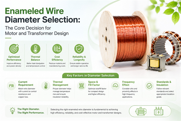
Today, we will systematically explain the methods, principles, and practical techniques for enameled wire diameter selection.
I. Understanding the Two Dimensions of Enameled Wire Diameter
Enameled wire diameter has two layers of meaning, and understanding both is the prerequisite for making the right choice.
Bare Conductor Diameter:
This refers to the diameter of the pure metal conductor after removing the insulating enamel film, usually expressed in millimeters (mm). Common specifications range from 0.018mm to 5.00mm, covering nearly 300 standard sizes.
Overall Diameter:
This refers to the total outer diameter of the enameled wire including the insulating enamel, determined by the bare conductor diameter plus the enamel thickness. According to the IEC standard Grade 1/2/3 classification, enamel thickness ranges from 0.01mm to 0.10mm.
The relationship between the two diameters is:
Overall Diameter = Bare Conductor Diameter + 2 × Enamel Thickness
For example: 0.50mm bare conductor + Grade 2 enamel = 0.50 + 0.064 = 0.564mm overall diameter.
II. International Standards for Enameled Wire Diameter
1. Metric Standard (IEC/GB)
The IEC 60317 series standards use the metric system (mm) and are the main internationally accepted standards. They give priority to the R20 and R40 preferred number systems, with specifications covering the full range from 0.018mm to 5.00mm. China’s GB/T 6109 series standards are equivalent to IEC 60317 and are fully accepted in the domestic market.
2. AWG Standard (American)
AWG (American Wire Gauge) is widely used in the North American market. The larger the number, the thinner the wire: AWG 30 equals approximately 0.255mm, AWG 20 equals approximately 0.812mm, and AWG 10 equals approximately 2.588mm.
The conversion between AWG and the metric system is not perfectly aligned, with certain rounding relationships, so special care is needed when designing across standards.
3. SWG Standard (British)
SWG (Standard Wire Gauge) is a traditional British standard, currently used mainly in the United Kingdom and some Commonwealth countries. The correspondence between SWG specifications and metric/AWG systems varies.
4. JIS Standard (Japanese)
JIS C 3202 is the Japanese industrial standard, used in Japan and some Asian markets, with a specification system close to IEC.
III. Eight Core Factors for Selecting Enameled Wire Diameter
1. Current Carrying Capacity
Current carrying capacity is the primary factor in diameter selection. When current passes through a conductor, it generates I²R losses. A diameter that is too thin will cause excessive temperature rise, accelerated insulation aging, and shortened service life.
Empirical formulas (copper conductor, 30°C ambient): 2A/mm² is safe and conservative, 3-4A/mm² is the general design range, and 5-6A/mm² is for compact design.
For example, a coil with a working current of 5A would be well matched by selecting a conductor of 2.0mm² (corresponding to a diameter of 1.6mm).
2. Slot Fill Rate
Slot fill rate is an essential indicator in winding design. The relationship between diameter selection and slot fill rate is: a diameter that is too large makes winding difficult, raises slot fill rate too high, and creates difficult insertion.
During winding design, slot fill rate is usually controlled between 75-85%. Exceeding 90% makes insertion difficult or even impossible; below 60% indicates poor space utilization, and a larger diameter or fewer turns should be considered.
3. Temperature Rise Limit
The temperature rise of enameled wire is closely related to diameter. The thinner the diameter, the higher the resistance, and the higher the temperature rise.
The temperature rise estimation formula is: Temperature Rise = k × I² × R × t
Design principles: control temperature rise within 80% of the enamel thermal class, and within 60% in critical applications, leaving sufficient safety margin.
4. Mechanical Strength
Enameled wire is subjected to mechanical stresses such as tension, bending, and vibration during operation. A diameter that is too thin results in insufficient mechanical strength and easy breakage, while a diameter that is too thick is difficult to bend and wind.
Generally, ultra-fine diameters below 0.10mm require special attention to mechanical strength.
5. Frequency Characteristics (Skin Effect)
In high-frequency applications, the skin effect significantly affects diameter selection. AC current tends to flow on the conductor surface, reducing the effective conductive area and increasing the equivalent resistance.
The skin depth formula is: δ = √(ρ / (π × f × μ))
For example, the skin depth of copper at 100kHz is approximately 0.21mm. If the diameter exceeds 2δ, skin effect losses will increase significantly.
High-frequency application strategies: single thick wire below 100kHz, multi-strand fine wire (Litz wire) from 100kHz-1MHz, and Litz wire or thin film above 1MHz.
6. Cost Factors
The cost of enameled wire is proportional to the square of the diameter (because cross-sectional area = πr²). Increasing from 0.50mm to 0.71mm (a 42% increase) results in a cost increase of about 100%.
Design optimization principles: minimum diameter that meets performance requirements, prioritize standardization, and comprehensively consider material cost and process cost.
7. Standardization Considerations
Prioritize standard specifications and avoid special specifications. Reasons include: standard specifications have abundant supply and low prices, standard specifications have shorter delivery times, and special specifications require customization with significantly higher costs.
R20 preferred number system (IEC 60317): 0.10, 0.112, 0.125, 0.14, 0.16, 0.18, 0.20, 0.224, 0.25, 0.28, 0.315, 0.355, 0.40, 0.45, 0.50, 0.56, 0.63, 0.71, 0.80, 0.90, 1.00…
8. Process Compatibility
Consider the limitations that winding processes place on diameter. Automatic winding machines usually require diameters above 0.05mm, manual winding can handle various diameters, and high-speed winding requires special treatment for fine wires.
IV. Diameter Selection for Different Application Scenarios
1. Home Appliance Motors
Home appliance motors (refrigerators, air conditioners, washing machines) typically use 0.30-0.80mm enameled copper wire, with Grade 1 or Grade 2 enamel, 130°C or 155°C thermal class, focusing on cost and manufacturability.
2. Industrial Motors
Industrial motors (servo motors, inverter motors) typically use 0.50-2.00mm enameled copper wire, with Grade 2 enamel, 180°C or 200°C thermal class, focusing on performance and reliability.
3. Transformers
Transformers (power transformers, switching power supplies) typically use 0.10-1.50mm enameled copper wire, with Grade 1 or Grade 2 enamel, 130°C-180°C thermal class, with high-frequency transformers using Litz wire.
4. Micro Special Motors
Micro special motors (vibration motors, stepper motors) typically use 0.02-0.30mm enameled copper wire, with Grade 1 enamel (thin film), focusing on precision and consistency.
5. Precision Instruments
Precision instruments (medical instruments, sensors) typically use 0.05-0.50mm enameled copper wire, focusing on stability and precision.
V. Standard Process for Diameter Selection
Step 1: Clarify Requirements
Define working voltage, working current, power density, temperature rise limit, working frequency, and environmental conditions.
Step 2: Initial Calculation
Calculate the required cross-sectional area, select the corresponding standard diameter, and consider enamel thickness.
Step 3: Process Verification
Conduct sample trial production, insertion testing, temperature rise testing, and performance testing.
Step 4: Optimization Confirmation
Conduct cost evaluation, standardization confirmation, supplier evaluation, and final selection.
VI. Common Misconceptions in Enameled Wire Diameter Selection
Misconception 1: The Thicker the Better
In fact, a diameter that is too thick leads to significant cost increases, excessive slot fill rate, difficult insertion, and increased weight.
Misconception 2: Only Consider Current Density
Current density is only one reference factor. A comprehensive consideration of temperature rise, heat dissipation, process, cost, and other factors is also necessary.
Misconception 3: Ignoring High-Frequency Effects
In high-frequency applications, the skin effect significantly increases losses, and blindly choosing thick wire actually reduces efficiency.
Misconception 4: Over-Pursuing Small Diameters
A diameter that is too thin brings problems such as insufficient mechanical strength, difficult winding, and poor consistency.
Misconception 5: Ignoring Enamel Thickness
The overall diameter is the true constraint in winding design, and the influence of enamel thickness cannot be ignored.
VII. FAQ
Q: How to determine the cross-sectional area of enameled wire?
A: Cross-sectional area S = I / J, where I is the working current and J is the current density. Copper conductors commonly use J = 3-5A/mm².
Q: How to convert between metric and AWG?
A: AWG and mm do not have a fully precise correspondence, only approximate conversion. Common reference table: AWG 20 ≈ 0.81mm, AWG 25 ≈ 0.45mm, AWG 30 ≈ 0.25mm.
Q: Should high-frequency applications use thick or thin wire?
A: Single thick wire is affected by the skin effect at high frequencies, with reduced effective cross-sectional area. Multi-strand fine wire (Litz wire) should be used instead, with each strand diameter less than 2 times the skin depth.
Q: What is the impact of enamel thickness on diameter selection?
A: The actual winding design must consider the overall diameter. Grade 1 enamel is thinner, Grade 3 is thicker. For the same bare conductor diameter, the Grade 3 overall diameter will be 0.02-0.05mm larger.
Q: How to choose the enamel grade?
A: Grade 2 is the most universal choice. If dense winding is needed, choose Grade 1. If high reliability or high voltage applications are needed, choose Grade 3.
Q: Is the diameter selection for enameled aluminum wire the same as for copper?
A: Not the same. The resistivity of aluminum is about 1.6 times that of copper. To achieve the same resistance, the aluminum cross-sectional area needs to be 1.6 times that of copper. Simple conversion: aluminum wire diameter = copper wire diameter × 1.28.
Q: What to do when standard specifications are insufficient?
A: Prioritize specifications in the R20 or R40 preferred number system. If still not satisfied, custom specifications can be made, but the cost will increase significantly.
Q: What is the impact of diameter tolerance on design?
A: Enameled wire diameters have tolerances, usually ±0.005mm to ±0.020mm. The design should calculate slot fill rate based on the maximum outer diameter and current carrying capacity based on the minimum cross-sectional area.
VIII. Ten Recommendations for Enameled Wire Diameter Selection
- Clarify Requirements: First determine key parameters such as working voltage, current, frequency, and temperature rise.
- Safety Margin: Control temperature rise within 60-80% of the enamel thermal class.
- Standardization First: Prioritize IEC 60317 standard specifications.
- Current Carrying Verification: Calculate and verify current carrying capacity using I = S × J.
- Slot Fill Rate Verification: Control slot fill rate between 75-85%.
- Special High-Frequency Considerations: Consider skin effect for high-frequency applications.
- Process Verification: Verify feasibility through sample trial production.
- Cost Optimization: Minimize cost while meeting performance requirements.
- Supplier Evaluation: Select suppliers with quality assurance.
- Continuous Improvement: Continuously optimize based on actual usage.
IX. Summary
Enameled wire diameter selection is a systematic engineering task that requires comprehensive trade-offs. There is no universally optimal solution, only the most reasonable choice for a specific application scenario.
Core Points:
- Two Dimensions: Bare Conductor Diameter + Enamel Thickness = Overall Diameter
- International Standards: IEC 60317 (metric), AWG (American), SWG (British)
- Eight Factors: Current carrying capacity, slot fill rate, temperature rise, mechanical strength, frequency characteristics, cost, standardization, process
- Five Scenarios: Home appliance motors, industrial motors, transformers, micro special motors, precision instruments