


Engineering Significance of the Dual-Layer Insulation System
Flat enameled copper wire (Flat Enameled Copper Wire / Rectangular Magnet Wire) insulation systems play a decisive role in motor service life. The term “dual-layer” does not refer to a simple physical stacking of two insulation films, but rather to a precisely engineered composite system comprising a base coat and an overcoat-designed for chemical compatibility and functional complementarity. The base coat provides electrical insulation and mechanical adhesion, while the overcoat delivers thermal resistance, chemical resistance, and abrasion/micro-abrasion resistance.
From a full-lifecycle perspective of motor manufacturing, insulation system failure accounts for approximately 35%–40% of total motor failures. In small- and medium-power high-efficiency motors, winding insulation failure typically manifests as turn-to-turn short circuits or ground breakdown. As the core carrier of winding insulation, the microstructure and long-term stability of the enameled copper wire’s insulation directly determine the motor’s operational service life and reliability class.
The base coat is commonly formulated using polyester (PE) or polyesterimide (PEI), corresponding to thermal classes F (155°C) and H (180°C), respectively. The overcoat typically employs polyamide-imide (PAI) to achieve Class 200 (200°C) or polyimide (PI) to attain Class 220 (220°C). Incorporation of either overcoat material elevates the overall thermal class of flat wire by 25–40°C above that of the base coat alone—this enhancement directly translates into increased thermal margin for windings operating under high-temperature hot spots and a rightward shift of lifetime on a logarithmic scale.
Specifically, under the dual-layer combination (PG2), Grade 2 breakdown voltage reaches up to 2.5 kV rms—approximately 6.4% higher than that of single-layer PG1 (2.35 kV rms). Dual-layer Grade 3 achieves >5 kV rms with thicker insulation (≥60 μm). These values are decisive for insulation safety margins in high-voltage motors (e.g., 800 V platform EV traction motors, HVDC traction systems) and long-life industrial motors (design life >20 years).
From the standpoint of insulation design redundancy, the safety margin of single-layer insulation degrades significantly under cumulative long-term thermal, mechanical, and electrical stresses. In contrast, the dual-layer system mitigates this degradation through electric field redistribution and stress buffering at the interfacial boundary between layers—reducing the degradation rate to approximately 30%–50%. Consequently, for an identical design life requirement (20 years), the initial breakdown voltage safety factor of dual-layer insulation can be reduced by 10%–15%, thereby decreasing insulation volume occupancy within the slot and enhancing motor power density.
Chemical Mechanism and Phase Interface of Dual-Layer Enamel Coatings
The long-term stability of dual-layer systems is highly dependent on the chemical compatibility and physical phase interface characteristics between the base coat and top coat. The base coat consists of thermosetting polyester or polyester-imide, whose molecular chains contain ester linkages (–COO–) and imide rings (–CONCO–), providing excellent flexibility and adhesion. The top coat comprises polyamide-imide (PAI) or polyimide (PI), whose molecular chains feature aromatic imide rings and amide linkages, delivering superior thermal resistance, chemical resistance, and mechanical strength.
Regarding chemical bonding mechanisms: the ester groups in the polyester-imide base coat form chemical bonds (Cu–O–C=O) with the copper surface oxide layer (Cu₂O/CuO) during high-temperature baking, providing initial adhesion. The polyamide-imide top coat undergoes condensation reactions via reactive end groups (e.g., –NCO, –COOH) with hydroxyl groups (–OH) present in the base coat, forming a covalent crosslinked network. This chemical bonding, together with interdiffusion of polymer chains, governs the long-term compatibility of the dual-layer system.
A transition layer (interphase) forms between the two layers via diffusion and covalent crosslinking during the baking process, with a thickness of approximately 5–10 μm. This interphase acts as a stress-relief buffer layer under thermal cycling and mechanical vibration, suppressing crack initiation and propagation within the enamel film. Empirical evidence shows that dual-layer enamel films lacking an optimized phase interface are prone to interfacial delamination under prolonged high-temperature aging (>180°C), resulting in localized insulation failure.
Phase interface failure modes fall into three primary categories: thermal stress delamination, chemical aging delamination, and mechanical vibration delamination. Thermal stress delamination arises from coefficient of thermal expansion (CTE) mismatch between the base and top coats—polyester-imide (PEI) exhibits a CTE of ~60–80 ppm/°C, whereas PAI exhibits a CTE of ~35–45 ppm/°C; this CTE difference generates interfacial shear stress during thermal cycling. Chemical aging delamination results from accelerated oxidative degradation at the interface region relative to the bulk material under prolonged thermo-oxidative aging. Mechanical vibration delamination originates from cyclic shear stress induced at the interface by electromagnetic vibrations during motor operation (typical frequency range: 100 Hz–10 kHz). A robust enamel design must achieve balanced performance across all three dimensions.
With respect to coating thickness, IEC 60317-0-2 defines three grades: Grade 1 (minimum 0.06 mm), Grade 2 (minimum 0.10 mm), and Grade 3 (minimum 0.16 mm), corresponding to distinct dielectric withstand requirements. In motor coil design, Grade 2 dominates, balancing slot fill factor and dielectric safety margin. In high-power-density applications such as EV hairpin windings, Grade 3 enamel usage is progressively increasing.
The plasticizer system within the enamel coating also critically influences the long-term stability of the dual-layer structure. Plasticizers in the base coat—typically triglycerides or epoxidized soybean oil—migrate toward the surface and volatilize over time, leading to embrittlement and reduced flexibility. The top coat functions as a barrier layer, retarding the migration rate of plasticizers; this “dual-protection” effect constitutes a key chemical foundation for the long-term durability of dual-layer enamel coatings.
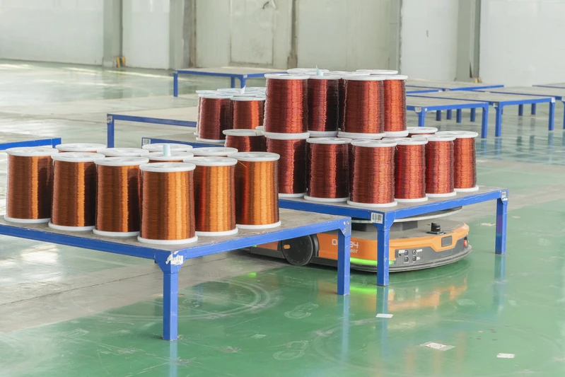
Rectangular Conductor Geometry and Material Systems
Flat enameled copper wire employs rectangular cross-section conductors (C11000 ETP / C10100 OFHC / C10200 OF / C12200 DHP), differing from round wire’s circular cross-section; the rectangular geometry achieves higher slot fill factor in motor slots. Round wire slot fill factor is approximately 0.45–0.55, whereas rectangular wire reaches 0.65–0.78—this value directly translates into enhanced motor power density and torque density.
Typical dimensional range: thickness 0.5–5.0 mm, width 2.0–15.0 mm, cross-sectional area 1–75 mm². Corner radius r ≥ 0.5 mm is a critical process parameter—insufficient corner radius induces stress concentration in the enamel coating during bending, leading to premature failure.
The core advantages of rectangular conductors over round conductors manifest across three dimensions: first, improved spatial utilization enabling higher power density; second, more uniform current distribution across the rectangular cross-section, resulting in lower skin-effect losses; third, simplified automated winding for end-turn forming (hairpin or “U-shaped” bending). In new-energy vehicle (NEV) traction motors, flat-wire hairpin windings offer three key advantages over round-wire windings: higher slot fill factor (20%–30% improvement), higher power density (15%–20% improvement), and superior thermal dissipation (due to larger end-turn contact area), establishing them as the de facto standard for 800 V platform EV flat-wire motors.
Rectangular conductor manufacturing processes include continuous casting and rolling (CCR) and Conform continuous extrusion; these processes exert distinct influences on copper rod grain structure and mechanical properties. CCR yields uniform microstructure and stable electrical conductivity; Conform processing achieves high dimensional accuracy along the edges but requires careful control of residual stresses induced by extrusion. Annealing (in-line annealing or bell-jar furnace annealing) eliminates cold-work hardening, ensuring conductor elongation meets the standard requirement of ≥30%.
Conductor material selection directly impacts enamel adhesion and motor electrical performance. C11000 ETP (electrolytic tough pitch copper) with conductivity ≥100% IACS is the mainstream choice; C10100 OFHC (oxygen-free high-conductivity copper) with conductivity ≥101% IACS is suitable for high-power-density applications; C12200 DHP (phosphorus-deoxidized copper) exhibits excellent resistance to hydrogen embrittlement, making it appropriate for hydrogen-containing environments (e.g., impregnation processes in oil-cooled motors). Prior to enameling, conductor surface condition must undergo micro-etching to achieve a surface roughness (Ra) of 0.5–2 μm, enhancing mechanical anchoring of the enamel coating.
Key Process Parameters for Dual-Layer Enamel Coating
The enameling process for rectangular magnet wire is more complex than that for round wire. Round wire can achieve uniform coating using a circular die, whereas rectangular wire requires a rectangular die (Rectangular Die / Slot Die) to ensure uniform enamel thickness across all four flat surfaces and four rounded corners of the rectangular cross-section.
Design and machining precision of the rectangular die are critical to enamel thickness uniformity. Internal die dimensions must account for volumetric shrinkage after curing (approximately 5%–8% for polyester; approximately 3%–5% for polyamide-imide), and special chamfering is applied to the four rounded corners of the rectangular cross-section. Die gap is typically controlled at 1.2–1.5 times the target enamel thickness to ensure complete filling of the gap under pressure and uniform coating on the conductor surface.
A typical enameling sequence is as follows:
Bare wire surface pretreatment (cleaning + micro-etching) → Primer application → Primer bake → Topcoat application → Topcoat bake → Take-upBoth primer and topcoat are applied in multiple passes (typically 4–8 passes), with each pass cured in either horizontal or vertical ovens. Oven temperature profiling is designed as follows: inlet zone at 320°C (solvent evaporation) → mid-zone at 420°C (chemical crosslinking) → outlet zone at 380°C (stress relaxation). Catalytic Gas Curing (CGC) enables low-temperature rapid curing at 280–320°C, particularly suitable for polyamide-imide topcoats.
Atmosphere control within the oven is also critical to enamel quality. Nitrogen purging (N₂ Purging) prevents high-temperature oxidative degradation of the enamel film—especially essential for polyimide topcoats—and requires oxygen concentration to be maintained within 50–500 ppm. CGC introduces catalytic gas (e.g., triethylamine) into the oven atmosphere, reducing enamel cure temperature by approximately 30–50°C. This is especially advantageous for composite coating systems comprising polyester-imide primers and polyamide-imide topcoats, minimizing excessive thermal degradation of the primer layer.
Critical process control parameters: enamel thickness uniformity (±10%), surface roughness (Ra ≤ 0.8 μm), oven temperature gradient (±5°C), and enameling speed (10–80 m/min, adjusted according to target enamel thickness).
Cleanroom environment during enameling is equally critical. Ambient particulate contamination (>5 μm) settling into the enamel bath causes surface defects, potentially leading to failures in continuity testing (saltwater pinhole test). Enameling facilities for premium-grade magnet wire must meet ISO 14644-1 Class 7 (10,000-class) or higher cleanliness levels; key coating stations may require Class 6 (1,000-class) conditions.
Long-Life Mechanism and Thermal Life Evaluation
The “long life” of motor windings is fundamentally a durability issue of the enamel film under coupled thermal, electrical, and mechanical stresses. Thermal life evaluation follows IEC 60172, using the Arrhenius model to extrapolate high-temperature accelerated aging data to the expected service life at operating temperature:
\log_{10} L = A + \frac{B}{T}
where L is time to failure (h), T is absolute temperature (K), and A and B are material constants. For Class H (180°C) polyester-imide enameled wire, operation at 200°C for 7,000 h retains ≥75% of breakdown voltage; extrapolation to 180°C yields a service life exceeding 20,000 h.
The core assumption of the Arrhenius model is that a single failure mechanism dominates across the entire temperature range. For dual-layer enamel systems, differing chemical compositions and degradation mechanisms between the base coat and top coat may render a single Arrhenius model insufficient for accurate full-life prediction. In practice, “dual-segment Arrhenius” or “reaction kinetics segmentation” approaches are commonly adopted—modeling base coat and top coat aging separately, then integrating their contributions for overall life estimation.
Key thermal life parameters include:
- Temperature Index (TI): Highest operating temperature corresponding to a 20,000 h life
- Heat Shock Temperature: Maximum temperature at which the enamel remains crack-free after 30 min exposure (Class F: 175°C / Class H: 200°C / Class 200: 220°C / Class 220: 240°C)
- Cut-through Temperature: Minimum temperature at which a heated probe, under specified load, penetrates the enamel film (≥300°C)
- Scraping Strength: Minimum force required for a scraper blade to breach the enamel film (≥5 N)
For dual-layer enamel systems, enhanced thermal life primarily stems from the top coat’s superior thermal resistance. For example, a PEI+PAI dual-layer system (Class 200) achieves a 20,000 h extrapolated temperature index of 200°C—representing a two-class improvement (>20°C) over single-layer PEI (Class 180).
Electrical aging also significantly impacts service life. Under variable-frequency drive (VFD) conditions, the enamel endures high-frequency pulse voltages (typical switching frequency: 5–20 kHz; dv/dt >1 kV/μs), and long-term partial discharge (PD) erosion constitutes another major failure mode. IEC 61934 and IEC 60034-18-41 specify impulse voltage endurance test methods for VFD motor windings, requiring windings to operate for ≥1000 h at 1.5× peak phase voltage without breakdown.
Mechanical aging further constrains enamel life. Motor windings experience three primary mechanical stresses during operation: electromagnetic vibration (typical range: 100 Hz–10 kHz), thermal expansion cycling stress (−40°C to +180°C), and centrifugal force (rotor winding end turns). Dual-layer enamel flexibility and mechanical strength compatibility are ensured collectively via winding bend radius (≥5× wire width), end-turn cushioning design, and impregnation processes (VPI / VPI+vacuum pressure impregnation).
Breakdown Voltage and Dielectric Properties
The breakdown voltage of flat enameled copper wire is a core parameter for evaluating insulation performance. IEC 60317-0-2 and GB/T 7095 specify the minimum breakdown voltage values for different insulation classes and enamel film thicknesses.
Typical breakdown voltages for rectangular wire:
| Insulation Type | Single-Layer PG1 (V rms) | Double-Layer PG2 (V rms) |
|---|---|---|
| Bare Conductor (No Enamel) | 350 | 560 |
| Grade 1 Enamel | 1350 | 1560 |
| Grade 2 Enamel | 2350 | 2560 |
| Grade 3 Enamel | 4750 | 5000+ |
The breakdown voltage improvement of double-layer PG2 over single-layer PG1 ranges from 6% to 25%. Notably, this improvement is not linearly additive—double-layer structures suppress electric field distortion at the interfacial layer, resulting in an actual breakdown field strength higher than the theoretical sum of single-layer enamel films.
Enamel film breakdown mechanisms comprise three types: electrical breakdown, thermal breakdown, and electrochemical breakdown. Electrical breakdown occurs within nanoseconds and correlates directly with the enamel’s dielectric strength; thermal breakdown occurs under prolonged (e.g., minute-scale) voltage application and depends on the enamel’s thermal conductivity and dielectric loss; electrochemical breakdown arises from long-term (e.g., year-scale) partial discharge and represents the primary mode of long-term enamel aging. Double-layer enamel exhibits superior performance over single-layer enamel across all three breakdown modes.
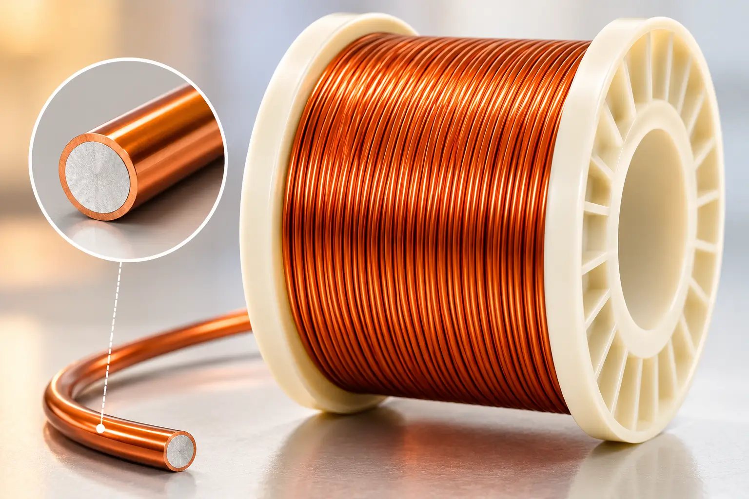
Dielectric strength is also frequency-dependent. Under pulse-width modulation (PWM) pulses from variable frequency drives (VFDs)—with switching frequencies of 5–20 kHz and rise times <1 μs—the enamel film experiences steep voltage transients (dv/dt > 1 kV/μs); the interfacial reflection effect in double-layer enamel significantly reduces erosion of the inner enamel layer by partial discharge.
The dielectric loss tangent (tan δ) is another critical parameter for evaluating enamel dielectric performance. For double-layer enamel, tan δ typically ranges from 0.005 to 0.015 at room temperature and increases exponentially with rising temperature. The tan δ of double-layer enamel is approximately 10%–20% lower than that of single-layer enamel, owing to the lower dielectric constant of the topcoat layer (e.g., polyamide-imide [PAI] ≈ 3.5, polyethylene [PE] ≈ 3.8), thereby reducing the overall effective dielectric constant.
Volume resistivity and surface resistivity are also key parameters characterizing enamel insulation performance. At room temperature, the volume resistivity of double-layer enamel typically ranges from 10¹⁴ to 10¹⁵ Ω·cm, retaining 10¹¹ to 10¹² Ω·cm at 150°C, ensuring insulation stability under elevated operating temperatures.
Motor Coil Application Families
Industrial Motor Stator Windings
The long-life design of industrial motors requires magnet wire to maintain insulation integrity over a 20-year service life. The dual requirements of high slot fill factor and high power density in IE3/IE4/IE5 high-efficiency motors have led to the progressive replacement of round wire with rectangular enameled copper wire in the medium- and low-power range (0.55–315 kW). Dual-layer insulation systems rated Class F (155°C) and Class H (180°C) provide ample insulation life margin under B-class (130°C) or F-class (155°C) temperature rise designs.
A typical manufacturing process flow for industrial motor stator windings includes: slot winding → forming → end-wedge/lacing → vacuum pressure impregnation (VPI) → curing → varnishing. Dual-layer enamel exhibits excellent compatibility during impregnation—epoxy or polyester impregnating resins form strong chemical bonds with the polyamide-imide (PAI) topcoat, further enhancing overall winding insulation performance.
New Energy Vehicle (NEV) Traction Motors
EV traction motors (400 V / 800 V platforms) employing hairpin-style rectangular winding technology impose extreme requirements on magnet wire:
- Peak phase voltage on 800 V platforms exceeds 550 V; enamel breakdown voltage must provide a safety margin >3×
- Oil-cooling (Oil Cooling) environments require enamel resistance to automatic transmission fluid (ATF)
- Sustained high temperatures (winding hot-spot >180°C) necessitate Class 200 or higher thermal class
- Skin effect at high frequencies (10–20 kHz) demands extremely tight enamel thickness uniformity (±5%)
Rectangular dual-layer polyetherimide + polyamide-imide (PEI+PAI) enameled wire (Class 200) has become the standard solution for EV hairpin motors on 800 V platforms.
Hairpin rectangular winding manufacturing differs significantly from conventional round-wire processes. Prior to winding, rectangular wire requires laser de-coating or mechanical de-coating to expose end regions for welding. Laser de-coating places exceptionally high demands on “controlled delamination” of the enamel—ensuring complete exposure of the weld zone while avoiding heat-affected zone (HAZ) expansion into the conductor (copper). High-quality dual-layer enamel exhibits clean, sequential layer removal during laser ablation (outer layer removed first, inner layer second), a critical characteristic for achieving high hairpin winding yield.
Rectangular enameled wire for 800 V platform EV motors must also comply with UL 1446 system certification (insulation system Class F/H) and IEC 60034-18-41 (pulse voltage withstand for inverter-fed motor windings). Automotive-grade component reliability standards AEC-Q100/Q200 are increasingly incorporated into the supply chain certification framework for rectangular enameled wire.
Wind Turbine Generators
Onshore and offshore wind turbine generators (1.5–18 MW), including doubly-fed induction generators (DFIG) and permanent-magnet synchronous generators with direct drive (PMSG-DD), extensively employ rectangular enameled copper wire in stator windings—particularly in high-power units (>3 MW). The salt fog corrosion environment of offshore wind demands enamel validation per dual testing per IEC 60068-52 (salt mist test, 96 h) and IEC 60068-2-60 (mixed flowing gas corrosion). The dual-layer PAI+polyimide (PI) system (Class 220) demonstrates significantly superior corrosion resistance in salt fog compared to single-layer PEI.
Wind turbine generator design life is typically 20–25 years; during this period, winding insulation must withstand combined stresses of long-term low-frequency vibration (blade-passing frequency harmonics at 0.5–3 Hz), thermal cycling (diurnal and seasonal variations), salt fog, and UV radiation (offshore). The weatherability and long-term stability of dual-layer enamel make it the preferred solution for wind turbine applications.
High-power wind turbine generators (>5 MW) commonly adopt stranded rectangular conductors to reduce skin-effect and eddy-current losses. Insulation treatment of such stranded configurations must ensure enamel integrity between individual strands; the uniformity advantage of dual-layer enamel is fully leveraged in this application.
Servo Motors and Robotic Joints
Industrial robot servo motors prioritize high torque density and rapid dynamic response (dynamic response frequency >1 kHz). Rectangular enameled copper wire delivers lower resistance (10–25% reduction vs. round wire) and higher slot fill factor, enabling 15–30% higher power density within identical outer dimensions. Dual-layer Class H (180°C) enamel provides thermal stability assurance under heavy-load and overload conditions (short-time 3× rated torque).
Collaborative robots (cobots) and humanoid robotic joint motors impose even stricter demands on insulation compactness. Rectangular enameled wire maximizes conductive cross-sectional area within minimal slot areas (typical 30–60 mm²), enabling joint motors to deliver high peak torque (short-time 5–10× rated) within small outer diameters.
Traction Motors and Rail Transit
Traction motors for urban rail transit (subways, trams) and mainline electric locomotives operate in harsh environments characterized by:
- Vibration and shock (IEC 61373 Category 1, Class B)
- Wide operating temperature range (−40°C to +180°C)
- Fire and flame retardancy (EN 45545-2 HL3, TB/T 3230)
- Long service life (30-year design)
Dual-layer polyimide (PI) enamel (Class 220) dominates this sector, its comprehensive performance—including high-temperature resistance, radiation resistance, and chemical resistance—meeting stringent rail transit insulation requirements.
The variable-frequency drive (VFD) operation of rail traction motors is especially severe: subway traction inverters typically switch at 1–3 kHz with voltage rise times <1 μs, generating substantial partial discharge (PD) over extended operation. IEC 60034-27 specifies PD test methodology, requiring partial discharge inception voltage (PDIV) ≥1.5× operating voltage. The interfacial design of dual-layer enamel offers structural advantages for PD suppression—the dielectric constant mismatch between topcoat and basecoat redistributes the electric field at the interface, reducing local field intensity and thereby increasing PDIV.
Appliances and Small Motors
Appliance motors—including air conditioner compressors, refrigerator compressors, and washing machine motors—commonly utilize dual-layer enamel (PE+PAI or PEI+PAI, Class F/H) to achieve >10-year service life and high reliability. Regarding compatibility with new environmentally friendly refrigerants such as R290 (propane), the PAI topcoat offers significant advantages over PE topcoat.
R290 (propane, GWP = 3), as a replacement for R22 and R410A, introduces new compatibility requirements for insulation materials. Under high-temperature, high-pressure conditions, R290 exhibits strong swelling capability; conventional PE topcoats suffer swelling, gloss loss, and degraded mechanical properties after prolonged R290 exposure. PAI topcoat demonstrates excellent R290 resistance, making it the preferred enamel system for R290-compressor motors.
Brushless DC (BLDC) motor penetration in appliance applications continues to increase. The high-frequency PWM drive of BLDC motors (typical switching frequency 20–80 kHz) imposes stricter requirements on enamel dielectric loss. The low dielectric loss property (tan δ < 0.015) of dual-layer PEI+PAI enamel results in lower temperature rise and higher efficiency in BLDC drive applications.
Test Methods and Standard System
Key tests for double-layer enameled rectangular copper wire include:
Electrical Tests
- Dielectric breakdown voltage (IEC 60851-3, ASTM D149)
- Film continuity (saltwater pinhole test, ASTM D1389)
- Insulation resistance (IEC 60851-5)
- Dielectric loss tangent (IEC 60851-6)
Thermal Tests
- Thermal shock (IEC 60851-6: mandrel wrap + 175/200/220°C × 30 min)
- Thermal aging (IEC 60172: 200°C × 168 h → dielectric breakdown voltage retention ≥75%)
- Softening breakdown (IEC 60851-6: cut-through temperature)
- Temperature index (IEC 60172 / IEEE 1 / ASTM D2307: 20,000 h extrapolation)
Mechanical Tests
- Elongation (IEC 60851-3: ≥30%)
- Springback angle (IEC 60851-3: ≤5°)
- Scratch resistance (IEC 60851-3: ≥5 N)
- Flexibility (mandrel bend + wrap)
Chemical Tests
- Solvent resistance (rubbing with alcohol or xylene; no film removal)
- Refrigerant resistance (immersion in R22, R134a, R290)
- Oil resistance (ATF oil at 100°C × 168 h)
- Hydrolysis resistance (95% RH × 96 h)
Core Standard System
- IEC 60317-0-2 (General specification for rectangular enameled copper wire) + -2 / -18 / -27 / -29 (rectangular wires with various enamel types)
- IEC 60317-8 (PEI round wire) + -13 (PI) + -25 (PEI+PAI double-layer round wire) + -46 (PAI+PI double-layer)
- IEC 60851 (Test methods series Parts 1–6)
- IEC 60172 (Temperature index testing)
- IEC 60085 (Electrical insulation thermal classification)
- NEMA MW 1000-2023 (e.g., MW 18 PEI / 46 PEI+PAI / 48 PAI)
- ASTM B49 (Round copper wire) / B193 (Resistivity) / B279 (Rectangular copper wire) / D2307 (Thermal aging) / D1676 (Dielectric breakdown)
- GB/T 7095 (Enameled rectangular wire) / GB/T 6109 (Enameled round wire) / GB/T 4074 (Test methods)
- JIS C 3202 (Enameled wire, 2014) / C 3210 (PE) / C 3211 (PU) / C 3212 (PI)
- UL 1446 (Insulation systems) / UL 1581 (Wire and cable)
- ISO 9001 / 14001 / 45001 / IATF 16949 (Automotive-grade quality management systems)
Selection and Engineering Application Guide
Selection of flat, double-coated enameled copper wire requires comprehensive consideration of thermal class, geometric dimensions, mechanical properties, and certification requirements.
Thermal Class Matching: Select the enamel coating thermal class based on the motor’s hot-spot temperature and required service life. Class F (155°C) is suitable for Class B (130°C) temperature rise designs; Class H (180°C) is suitable for Class F (155°C) temperature rise designs; Class 200/220 is suitable for Class H (180°C) or higher temperature rise designs.
Geometric Dimensions: The thickness-to-width ratio (t/w) of the rectangular cross-section typically ranges from 0.2 to 0.6. Thinner thickness facilitates bending and forming, while wider width provides larger cross-sectional area. In high-current applications (e.g., energy storage PCS, wind power converters), cross-sectional area can reach 30–75 mm²; in EV hairpin windings, typical thickness is 1.5–3.0 mm and width is 4.0–8.0 mm.
Certification Matching: Automotive-grade motors require suppliers certified to IATF 16949 plus component-level validation per AEC-Q100/Q200; rail transit applications require fire resistance per EN 45545-2 HL3 and vibration resistance per IEC 61373; medical and defense applications require industry-specific qualifications.
Supplier Capability: In addition to enamel coating performance, evaluate the supplier’s rectangular die precision, batch-to-batch consistency, capability for custom dimensions (typical die development lead time: 4–8 weeks), and coverage of international certifications (e.g., IEC 60317, NEMA MW 1000, ASTM B566, UL 1446).
Development Trends in Long-Life Motor Coil Design
The application of flat double-coated enameled copper wire in long-life motor coils is evolving from single-purpose thermal endurance enhancement toward multifunctional integration. Key next-generation technologies include:
Composite insulation systems (enamel coating + fiber covering)—adding a braided fiberglass or polyester (Dacron) layer over the double enamel coating to further elevate the temperature rating to 250°C (e.g., Class 250 per NEMA MW 41–44 + double enamel).
Low-dielectric-constant enamel coatings, applied in high-frequency motors (e.g., high-frequency transformers and motors operating above 100 kHz), reduce eddy current losses and improve system efficiency.
Smart enamel coatings, incorporating stress-indicating or temperature-sensing functionality—enabling online monitoring of enamel health status via nano-scale tracer particles embedded within the enamel.
Conclusion
Double-layer flat enameled copper wire, as the core material for motor coil windings, plays a critical role in the reliability design of long-life motors. Its technical advantages stem from the chemical complementarity and interfacial design between the base coat and top coat: the base coat provides electrical insulation and mechanical adhesion, while the top coat delivers thermal resistance, chemical resistance, and abrasion resistance.
In EV traction, wind power generation, rail transit, home appliances, and industrial motors, double-layer enamel systems—such as PE+PAI, PEI+PAI, and PAI+PI—have become standard solutions. The maturity of the standardized testing framework—comprising IEC 60317, IEC 60851, IEC 60172, NEMA MW 1000, and GB/T 7095—provides a robust foundation for design and material selection.
Motor designers must holistically evaluate thermal class, geometric dimensions, mechanical properties, certification requirements (e.g., UL 1446, ASTM B566), and supplier capabilities to balance insulation life margin, space factor, and cost. In high-end applications—including 800 V EV platforms, offshore wind power, and rail transit—double-layer enamel systems, combined with precise process control and full-lifecycle quality management (e.g., IATF 16949), constitute the core assurance for achieving motor design lifetimes of 15–30 years.