


Induction coils are electrical components made of conductors wound around each other to generate a magnetic field, transfer energy, or induce current through electromagnetic induction. They are widely used in induction heating, wireless charging, RFID/NFC, solenoid valves, medical imaging equipment, and scientific experimental devices. Copper (copper magnet wire) is the main conductor material of the induction coil, and its selection directly determines the coil’s Q value, efficiency, temperature rise, and long-term reliability.
The requirements for copper wire in induction coils differ systematically from those for transformer windings and motor windings. The former prioritizes high-frequency losses, Q value, and consistency, and is more sensitive to coating uniformity than temperature rise tolerance; the latter prioritizes current density, thermal aging, and mechanical reliability. This difference in selection focus makes copper wire for induction coils a distinct sub-field of electrical wire.
This article systematically elaborates on the engineering selection of copper enameled wire for induction coils from seven dimensions: conductor specifications, enamemel coating system, electrical parameters, application classification, Litz wire selection, winding process, and procurement and acceptance.
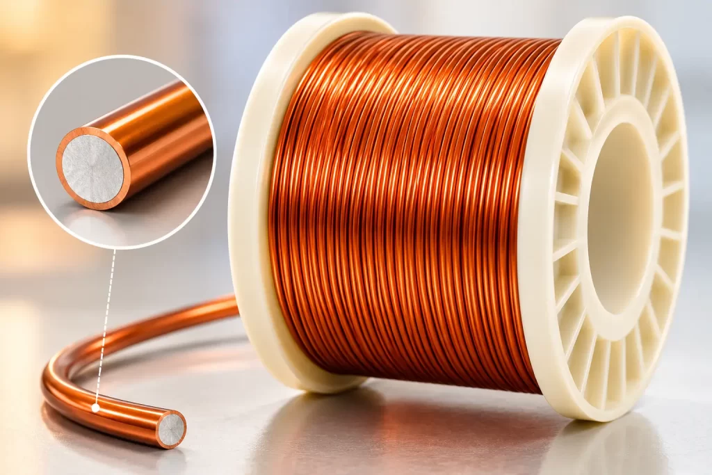
I. Engineering Requirements for Copper Wire in Induction Coils
Operating Characteristics of Induction Coil
The operating conditions of an induction coil are fundamentally different from those of a transformer or a motor:
- Wide Frequency Range: From 50 Hz power frequency to MHz-level high frequencies (wireless charging 100–205 kHz, RFID 13.56 MHz, microwave heating 2.45 GHz), spanning 6 orders of magnitude. – High Q-Value Requirement: RF coil Q-values are typically >100, and in some applications >300, directly determining system efficiency. – Significant Skin Effect: At high frequencies, wire diameter is strictly constrained by skin depth, resulting in equivalent AC resistance much greater than DC resistance. – Sensitive to Parasitic Parameters: Distributed capacitance and proximity effect losses significantly impact coil performance. – Temperature Rise Constraints: RF coils often rely on natural heat dissipation, resulting in a small temperature rise margin. – Small Batch/Customization: Small batch sizes and diverse specifications require high flexibility from suppliers.
Differences between induction coils and transformer/motor windings
| Dimension | Induction coil | transformer | small motor |
|---|---|---|---|
| Operating frequency | 50 Hz – Hundreds of MHz | 50/60 Hz | 50/400 Hz |
| Key Indicators | Q value, inductance accuracy, SRF | Efficiency, Temperature Rise | Torque, temperature rise, lifespan |
| enamel coating thickness | Ultra-thin (Grade 1) | Medium (Grade 2) | Medium (Grade 2) |
| wire diameter selection | Constrained by skin depth | Constrained by current density | Constrained by current density |
| High frequency loss | Decisive indicators | Secondary indicators | Medium indicators |
| Mechanical stress | Low | Medium (vibration) | High (vibration) |
Industry Chain Positioning of Copper Wire for Induction Coils
Induction coil copper wire belongs to the high-frequency application subcategory of the broad category of magnetic wire, and its main applications include:
- Industrial induction heating: 50 Hz – 100 kHz – Wireless charging (Qi/WPC): 100 – 205 kHz – Induction cooking: 20 – 50 kHz – RFID/NFC: 125 kHz – 13.56 MHz – Solenoid: DC – several kHz – Medical imaging (MRI gradient coil): kHz level – Laboratory-specific coils (Tesla coil, Helmholtz coil): 10 kHz – hundreds of kHz
The global annual demand for copper wire for induction coils is approximately 250,000–350,000 tons, accounting for 12%–15% of the total output of copper wire for induction coils. Among them, wireless charging and induction heating account for more than 60%.
II. Conductor Specifications and Wire Diameter Selection
Applicable Scenarios for round wire, flat wire, and Litz wire
| conductor morphology | Applicable Scenarios | Engineering Reasons |
|---|---|---|
| round wire | Low-frequency induction coils (< 100 kHz), power frequency solenoid valves, induction cookers | Simple to wind and low cost |
| flat wire | High-current induction heating (>100 A), high-power-density coil | High slot fill rate and good heat dissipation |
| Litz line | High-frequency wireless charging, RFID, induction heating (> 100 kHz) | Suppress the skin effect and reduce AC resistance |
| Silver-plated copper wire | MHz-level high-frequency, Qi wireless charging precision coil | High surface conductivity and low high-frequency loss |
Constraints of Skin Depth on Wire Diameter
Skin depth δ calculation formula (copper conductor, 20°C):
δ = √(ρ / (π × f × μ₀))
Where ρ = 1.724 × 10⁻⁸ Ω·m, μ₀ = 4π × 10⁻⁷ H/m.
| Frequency (f) | Skin depth δ (mm) | Recommended maximum single-strand wire diameter (≤ 2δ) |
|---|---|---|
| 50 Hz | 9.34 | 18.7 mm (unconstrained) |
| 1 kHz | 2.09 | 4.2 mm |
| 10 kHz | 0.66 | 1.3 mm |
| 100 kHz | 0.21 | 0.42 mm |
| 1 MHz | 0.066 | 0.13 mm |
| 10 MHz | 0.021 | 0.042 mm |
| 13.56 MHz | 0.018 | 0.036 mm |
Engineering experience: The wire diameter of the induction coil should be ≤ twice the skin depth (δ). When the operating frequency is > 100 kHz and the single-strand wire diameter is limited (< 0.4 mm), Litz wire (multi-strand insulated fine wire stranded together) should be used to effectively utilize the conductor cross-sectional area.
IEC 60317 Preferred Wire Diameters specifications
Common wire diameters for induction coils (IEC 60317 preferred specifications):
| Nominal diameter (mm) | Diameter tolerance (mm) | Typical induction coil applications |
|---|---|---|
| 0.040 | ±0.002 | RFID high-frequency coil |
| 0.071 | ±0.003 | Litz wire single strand (wireless charging) |
| 0.100 | ±0.005 | Litz wire single strand, RFID fine coil |
| 0.200 | ±0.005 | High-frequency Litz wire, induction heating |
| 0.315 | ±0.006 | Wireless charging main winding |
| 0.500 | ±0.010 | Induction heating, solenoid valve |
| 0.800 | ±0.015 | Power frequency induction coils, induction furnaces |
| 1.000 | ±0.015 | High-power induction heating |
For high-frequency applications (>100 kHz), the wire diameter accuracy requirements are significantly higher than those for power frequency applications. The diameter tolerance is generally controlled within ±0.005 mm to avoid deviations in coil inductance consistency.
III. enamel coating type and thermal class selection
Main enamel coating types and engineering characteristics
The selection logic for enamel coating in induction coils differs from that for motor windings—the former focuses more on the uniformity of enamel coating thickness (affecting inductance consistency) and dielectric loss (tan δ), while the latter focuses more on mechanical strength and heat resistance.
| enamel coating type | IEC abbreviation | thermal class (°C) | Key engineering characteristics | Typical induction coil applications |
|---|---|---|---|---|
| polyurethane | UEW | 130 | 380°C direct welding, thin and uniform enamel coating, low dielectric loss. | RFID, wireless charging, precision instrument coils |
| polyester | PEW | 155 | Good heat resistance and high mechanical strength | Power frequency induction coils, induction furnaces |
| polyesterimine | EIW | 180 | Resistant to thermal shock and chemicals | High-power induction heating, solenoid valve |
| Polyamide-imide | AIW | 200 | Softening breakdown at 330–350°C, scratch resistant, and with optimal mechanical properties. | High-power induction heating, medical imaging |
| polyimide | PIW | 220 | Extremely high temperature, flame retardant | Military and aerospace high-frequency coils |
| Self-adhesive enameled wire | SB | 130–180 | Heating or solvent can self-adhere | Frameless coil, impregnation-free |
Selection of enamel coating grade (thickness)
The relationship between enamel coating grade and induction coil performance:
| Application scenarios | Recommended level | Engineering Reasons |
|---|---|---|
| High-frequency precision coils (RFID, wireless charging) | Grade 1 | The enamel coating is thin, has good inductance consistency, and low distributed capacitance. |
| Medium frequency induction heating (20–100 kHz) | Grade 2 | Performance/space balance |
| High-power power frequency induction coil | Grade 2 or 3 | Impact resistant and wear resistant |
| Impregnation process coil | Grade 1 or 2 | Impregnated varnish for insulation |
For high-frequency applications, Grade 1 enamel coating must be selected: for every 0.01 mm increase in enamel coating thickness, the distributed capacitance increases by about 3%–5%, and the self-resonant frequency (SRF) decreases accordingly, which has a significant impact on the frequency characteristics of MHz-level coils.
IEC Insulation thermal class and enamel coating Mapping
| Insulation class | Maximum operating temperature (°C) | I recommend enamel coating | Typical induction coil applications |
|---|---|---|---|
| E | 120 | UEW | RFID, low-power wireless charging |
| B | 130 | UEW / PEW | Power frequency solenoid valves, household appliance induction coils |
| F | 155 | PEW / EIW | Induction heating, induction cooker |
| H | 180 | EIW | High-power induction heating, induction furnace |
| N | 200 | AIW | Special high-frequency sensing and medical imaging |
| R | 220 | PIW | Military industry, aerospace high frequency |
Design principle: The temperature rise of the induction coil is usually lower than that of the motor (RF coils rely on natural heat dissipation, with a temperature rise of 30–60 K), but the dielectric loss will increase with the temperature. The thermal class should be selected with an engineering margin of 10–15 K.
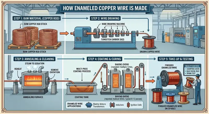
IV. Key Electrical Parameters
DC Resistance and AC Resistance of Conductors
DC resistance formula (20°C):
R_dc = ρ × L / A
Where ρ = 1.724 × 10⁻⁸ Ω·m (TU1 pure copper), L is the average turn length of the winding (m), and A is the cross-sectional area (m²).
AC resistance (high frequency):
R_ac = R_dc × F_r
F_r is the AC resistivity (> 1), determined by both the skin effect and the proximity effect. The skin effect F_r of a single round wire (approximately using Kramer’s formula):
F_r ≈ 1 + (r / (2δ))⁴ (when r ≤ δ)
F_r ≈ (r / (2δ)) + 0.26 + 0.07 × (2δ / r) (when r > 1.5δ)
Q Value (Quality Factor) Calculation
The Q value of a coil is defined as the ratio of inductive reactance to total loss resistance:
Q = ωL / R_total = 2πf × L / R_total
Where R_total = R_dc + R_ac + R_dielectric + R_radiation (total loss resistance).
Engineering significance:
| Q value range | Applicable Scenarios | Engineering trade-offs |
|---|---|---|
| Q < 50 | Low frequency induction heating | High losses and low efficiency |
| 50 < Q < 100 | General wireless charging | mainstream solutions |
| 100 < Q < 200 | High-efficiency wireless charging, resonant circuit | Recommended value |
| Q > 200 | Precision resonance, filter, MRI | High-end applications |
| Q > 300 | Laboratory Precision Coils | Litz Wire + silver plating |
For every 10% increase in Q value, the efficiency of the wireless charging system improves by about 1%–2%, making it a core indicator for high-frequency coil design.
Self-Resonant Frequency (SRF) and Parasitic Capacitance
Coil self-resonant frequency:
f_SRF = 1 / (2π × √(L × C_p))
Where C_p is the distributed capacitance of the coil (typically 2–10 pF).
Design experience: When the operating frequency > f_SRF / 3, the coil inductance characteristics begin to deviate from the ideal value and must be checked according to the transmission line model.
Engineering measures to reduce distributed capacitance:
- Use Grade 1 enamel coating (thin enamel coating) – Choose a larger wire diameter but fewer turns – Employ multi-section winding – Use Litz wire to reduce the diameter of a single strand
Skin Effect and Proximity Effect Loss
Skin effect: The current inside a single conductor tends to be distributed on the surface, reducing the equivalent conductive area.
Proximity effect: The magnetic field of an adjacent conductor induces eddy currents in another conductor, causing additional losses. In closely wound coils, proximity effect losses are typically 2–5 times greater than skin effect losses, and are a major source of losses in high-frequency coils.
Suppression methods:
- Use Litz wire (each wire diameter ≤ 2δ) – Increase turn spacing (reduce fill factor to below 60%) – Use segmented windings – Use ferrite cores to share the magnetic field
Dielectric Loss (tan δ)
enamel coating dielectric loss tangent:
tan δ = ε” / ε’
Typical values: – UEW/130: tan δ ≈ 0.005–0.010 (1 MHz) – PEW/155: tan δ ≈ 0.010–0.015 – EIW/180: tan δ ≈ 0.012–0.020 – AIW/200: tan δ ≈ 0.015–0.025
For high-frequency applications (> 1 MHz), UEW (with the lowest dielectric loss) should be selected.
V. Application Classification and Typical Coil Types
Induction Heating Coil
Industrial induction heating covers a frequency range from kHz to MHz.
| frequency | Power range | Typical applications | Copper wire selection |
|---|---|---|---|
| 1–10 kHz | 100 kW – several MW | Through heating of large workpieces and forging heating | flat wire 5×10 mm to 10×20 mm |
| 10–100 kHz | 10–500 kW | Surface hardening and brazing | round wire Φ2–6 mm or flat wire |
| 100 kHz – 1 MHz | 1–100 kW | Small-scale quenching and induction brazing | Litz wire Φ0.10–0.30 mm |
| 1–10 MHz | < 10 kW | Precision welding, semiconductor heating | Litz wire Φ0.05–0.10 mm |
Hollow copper tubes are another option for high-power induction heating—water cooling and hollow conductors simultaneously solve the skin effect and heat dissipation problems, with mainstream specifications ranging from Φ6×1 mm to Φ20×2 mm.
Wireless Charging Coil (Qi Standard)
Engineering parameters for the Qi standard (Wireless Power Consortium):
| parameter | Qi Low Frequency (5 W) | Qi Intermediate Frequency (15 W) | Qi High Frequency (50 W+) |
|---|---|---|---|
| Operating frequency | 110–205 kHz | 110–205 kHz | 127–150 kHz |
| Recommended line type | Litz wire Φ0.08 × 50 strands | Litz wire Φ0.10 × 100 strands | Litz wire Φ0.10 × 200 strands |
| outer diameter of coil | 30–40 mm | 40–50 mm | 50–70 mm |
| enamel coating type | UEW/130 Grade 1 | UEW/130 Grade 1 | UEW/130 Grade 1 |
| Q value requirement | > 50 | > 80 | > 100 |
The mainstream solution for wireless charging coils is Litz wire (each strand ≤ Φ0.10 mm, single-strand insulation) + Grade 1 UEW enamel coating + high-frequency Q value design.
RFID/NFC Coil
The operating frequency of RFID determines the selection of copper wire:
| frequency band | frequency | Typical applications | wire diameter/structure |
|---|---|---|---|
| LF | 125–134 kHz | Animal recognition, access control | round wire Φ0.10–0.30 mm |
| HF | 13.56 MHz | bus card, ID card | round wire Φ0.05–0.10 mm or etched aluminum |
| UHF | 860–960 MHz | Logistics, Retail | Etched aluminum |
The key indicators of RFID coils are inductance accuracy (±2%) and Q value (Q > 30 in HF band). The uniformity of the enamel coating directly affects the inductance consistency.
Solenoid Valves and Relay Coils
The operating frequency of a solenoid coil is typically DC to several kHz, and its operating characteristics are as follows:
- Long continuous energizing time (DC coil) – Limited temperature rise margin – High long-term reliability requirements (15-year lifespan for automotive solenoid valves)
Copper wire selection:
- Wire diameter: Φ0.10–0.50 mm – enamel coating: UEW/130 or PEW/155 – enamel coating grade: Grade 1 or 2 – thermal class: Class B or F
Special Coils for Laboratory and Teaching Use
Special applications for Tesla coils, Helmholtz coils, Rogowski coils, etc.:
| Coil type | Operating frequency | wire diameter | enamel coating |
|---|---|---|---|
| Tesla coil (primary) | 100–500 kHz | Φ1.5–3.0 mm | PEW/EIW Grade 2 |
| Tesla coil (secondary) | 100–500 kHz | Φ0.20–0.50 mm | UEW Grade 1 |
| Helmholtz coil | DC – 1 kHz | Φ0.30–1.00 mm | UEW/PEW |
| Rogowski coil | 50/60 Hz | Φ0.50–2.00 mm | PEW/EIW |
Tesla coil secondary windings require self-bonding wire. Heating or using a solvent can cure the coil into a self-supporting structure, eliminating the need for a frame.
VI. Litz Wire Selection
Working principle and construction of the Litz line
Litz wire is made of multiple independently insulated fine copper wires twisted together, each with a diameter ≤ 2δ (skin depth), which makes the current distribution in each wire uniform and the overall AC resistance close to the DC resistance.
Typical construction:
| Structure type | Single strand diameter | Number of shares | Total outer diameter | Applicable frequency |
|---|---|---|---|---|
| Type 1 | 0.040 mm | 10–50 | 0.3–1.0 mm | < 500 kHz |
| Type 2 | 0.071 mm | 50–200 | 1.0–3.0 mm | < 1 MHz |
| Type 3 | 0.100 mm | 100–500 | 2.0–5.0 mm | < 300 kHz |
| Type 4 | 0.200 mm | 50–200 | 4.0–8.0 mm | < 100 kHz |
| Type 5 | 0.050 mm | 200–1000 | 3.0–6.0 mm | 1–10 MHz |
Application Boundaries of the Litz line
Suitable scenarios for Litz line:
- Operating frequency 100 kHz – 10 MHz – Requires suppression of skin effect and proximity effect – High Q value requirement (> 100) – Low cost sensitivity
Scenarios where the Litz line is not applicable:
- Power frequency (< 1 kHz): A single thick round wire is sufficient. – High current (> 50 A): Too many strands significantly increase cost; copper tubing is recommended. – Very low frequency DC: A single round wire is sufficient. – Extreme temperature (> 200°C): Litz wire stranded structure has poor high-temperature stability.
Litz Wire specifications and Naming Rules
IEC 60317-11 (Litz wire product standard) and NEMA MW 1000-2018 specify the naming rules:
Wire diameter × Number of strands × Number of strand groups / Single strand diameter
Example:
- 0.1 × 50 × 5 / 0.071 mm: Total outer diameter 0.1 mm, 50 strands, divided into 5 groups, single strand diameter 0.071 mm – 105 × 0.10 mm: 105 strands, single strand 0.10 mm (standard Litz wire naming)
Engineering experience: The equivalent cross-sectional area of Litz wire should not be less than 80% of that of a single round wire with the same current capacity; otherwise, the equivalent resistance will be too high and the Q value will decrease.
VII. Mechanical Properties and Winding Process
Flexibility and Bending Performance
The copper wire of the induction coil needs to undergo multiple bends during the winding process:
- Elongation (soft conductor): ≥ 30% – Spring Angle (Φ0.5 mm): ≤ 8° – Minimum Bending Radius: ≥ 2 × conductor diameter – Repeated Bending Test (90° bend ≥ 5 times): enamel coating does not crack
Abrasion resistance of enamel coating (IEC 60317)
| Nominal diameter (mm) | Level 1 mean failure force (N) | Level 2 mean failure force (N) |
|---|---|---|
| 0.100 | 0.80 | 1.30 |
| 0.200 | 1.20 | 1.95 |
| 0.315 | 1.50 | 2.40 |
| 0.500 | 2.10 | 3.45 |
| 0.800 | 2.65 | 4.30 |
| 1.000 | 3.00 | 4.85 |
For high-frequency precision coils, Grade 1 (thinnest) enamel coating should be selected, but the winding tension needs to be more strictly controlled (to avoid scratches on the enamel coating that could cause short circuits between turns).
Winding Tension and Winding Speed
Winding tension (graded by wire diameter):
| wire diameter | Tension range (g) | Remark |
|---|---|---|
| Φ0.05–0.10 mm | 1–3 | Extremely low tension |
| Φ0.10–0.30 mm | 3–10 | Mainstream Litz line |
| Φ0.30–0.80 mm | 10–25 | General coil |
| Φ1.00–2.00 mm | 25–60 | High power coil |
Wrapping speed:
- High-frequency precision coils: 5–10 m/s – Litz wire winding: 3–8 m/s – General induction coils: 10–20 m/s
Excessive tension can cause thin wires to become thinner (especially thin single strands of Litz wire) and cause micro-cracks in the enamel coating; insufficient tension can cause loose coils, unstable interlayer capacitance, and difficulty in winding.
Impregnation and Encapsulation Process
The induction coil impregnation process improves insulation reliability and heat dissipation performance:
| Impregnating paint | thermal class | Process characteristics | Typical applications |
|---|---|---|---|
| Epoxy Impregnation Paint | 155–180°C | VPI (Vacuum Pressure Impregnation) | Industrial induction heating |
| polyester impregnation paint | 130–155°C | Atmospheric pressure impregnation | Universal Induction Coil |
| Silicone impregnation varnish | 180–220°C | High temperature curing | High-temperature induction heating |
| polyurethane impregnation varnish | 130°C | Self-curing, low-temperature process | Small precision coil |
Special attention should be paid to the impregnation of Litz wire – the impregnating varnish should fully penetrate the gaps between the strands, and after curing, it should not form bridging between the Litz wire strands (affecting flexibility).
VIII. Procurement and Acceptance
Key Factors in Selection
When purchasing copper wire for induction coils, nine core parameters must be considered:
- Conductor Material: Pure Copper TU1 / Oxygen-Free Copper OFC / Silver-Plated Copper Wire / CCA 2. Conductor Specifications: Round wire diameter / Flat wire thickness × width / Number of Litz wire strands × Single strand diameter 3. Enamelling Type: UEW / PEW / EIW / AIW / SB (Self-adhesive) 4. Thermal Class: Class E (120°C) / B (130°C) / F (155°C) / H (180°C) / N (200°C) / R (220°C) 5. Enamelling Grade: Grade 1 (Thin) / Grade 2 (Medium) / Grade 3 (Thick) 6. Standards: IEC 60317 / NEMA MW 1000 / GB/T 6109 / JIS C 3202 7. Litz Wire Standard: IEC 60317-11 / ASTM B174 8. Packaging Specifications: Bollard Weight (5 kg / 10 kg / 30 kg) 9. Certification Requirements: UL / REACH / RoHS
Incoming Quality Control (IQC)
| Inspection items | method | Judgment criteria |
|---|---|---|
| conductor diameter | micrometer | ±0.002 mm (high frequency) / ±0.005 mm (power frequency) |
| enamel coating thickness | Microthickness Measurement | IEEE 57 / IEC 60851 |
| enamel coating continuity | Pinhole test | < 5 holes / 30 m |
| DC resistance | resistance bridge | ≤ 0.01724 Ω·mm²/m (20°C) |
| Breakdown voltage | High voltage test | ≥ 1.8 kV (Grade 1) |
| Softening and Breakdown | Oven + Breakdown | ≥ 200°C (according to enamel coating) |
| Solderability | 380°C Immersion Tin | ≤ 3 s Unfinished paint (UEW) |
| elongation | Tensile test | ≥ 30% (soft state) |
| Self-adhesion strength | Heat self-adhesive thread at 110°C for 1 hour. | Shear strength ≥ 1 MPa |
Key Points for Supplier Evaluation
| Evaluation Dimensions | Key Indicators |
|---|---|
| Quality Management System | ISO 9001, ISO 14001, IATF 16949 (required for automotive coils) |
| Production equipment | Imported painting machines (SICME from Italy, MAG from Germany, Tanaka from Japan) |
| Detection capabilities | Own laboratory (including Q-value testing station and network analyzer), UL certified. |
| Litz line Capacity | High-speed stranding machine, braiding machine, group insulation equipment |
| Industry experience | ≥ 10 years of experience in enameled wire production, ≥ 5 years of experience in Litz wire production |
| Client Cases | Collaboration with wireless charging brands, automotive coil manufacturers, and medical equipment manufacturers |
Cost and Price Range
Relative price of copper wire for induction coils (by enamel coating and structure):
| Product Form | enamel coating | Relative Price (Copper Wire Base) |
|---|---|---|
| round wire | UEW/130 | 1.05–1.10× |
| round wire | PEW/155 | 1.15–1.25× |
| round wire | EIW/180 | 1.30–1.45× |
| round wire | AIW/200 | 1.50–1.70× |
| Silver-plated round wire | UEW | 1.40–1.60× |
| Litz line (100 shares) | UEW | 2.50–3.50× |
| Litz line (500 shares) | UEW | 4.00–6.00× |
| Self-adhesive enameled wire | UEW-SB | 1.30–1.50× |
Engineering experience: The cost of copper wire in induction coils accounts for 5%–25% of the total BOM (up to 30% for wireless charging coils). When selecting a model, three indicators should be considered comprehensively: material cost, system efficiency gain brought about by Q value improvement, and after-sales claim rate.
Storage and Usage Management
Storage conditions: Temperature 15–25°C, relative humidity 40%–60%, avoid direct sunlight, shelf life ≤ 12 months (Litz line ≤ 6 months).
Usage Management: First-In-First-Out (FIFO), use within 48 hours after opening, visual inspection before winding (enamel coating color, damage), random inspection before online (resistance, breakdown).
Summary: Engineering Selection Guidance for Copper Wire in Induction Coils
For induction coil copper wire selection, the operating frequency is the primary parameter that determines conductor geometry and insulation scheme. At DC to 1 kHz, single-strand round wire (Φ0.30–2.00 mm) combined with UEW or PEW Grade 2 enamel coating is sufficient because skin depth (9.34 mm at 50 Hz, 2.09 mm at 1 kHz) far exceeds any practical wire diameter. At 1 kHz to 100 kHz, single-strand round wire (Φ0.20–1.00 mm) with UEW or PEW Grade 1 is the mainstream choice for induction cookers and medium-frequency industrial heating. Above 100 kHz, the wire diameter becomes constrained by skin depth (only 0.21 mm at 100 kHz), making Litz wire the only viable solution; Grade 1 UEW is required to minimize distribution capacitance and maximize Q value. From 1 MHz to 10 MHz, Litz wire with finer single-strand diameter (0.05 mm or smaller) is essential to reduce proximity effect losses. Above 10 MHz, silver-plated copper wire or specially processed Litz wire is necessary because copper’s surface conductivity at microwave frequencies becomes the limiting factor.
The application scenario further refines the selection matrix across six major categories. Industrial induction heating at power frequency uses PEW/155 with Φ2–10 mm round wire or rectangular conductors; high-frequency induction heating requires Litz wire combined with AIW/200 Grade 2 for thermal endurance. Qi-standard wireless charging (5–50 W) is dominated by Litz wire Φ0.08–0.10 mm with UEW Grade 1, where Q value targets are > 50, > 80, and > 100 for 5 W, 15 W, and 50 W systems respectively. RFID and NFC coils operating at 125 kHz or 13.56 MHz use fine round wire (Φ0.05–0.30 mm) with UEW Grade 1 because inductance precision (±2%) and Q value consistency outweigh mechanical robustness. Solenoid valves for DC or low-frequency AC applications use round wire Φ0.10–0.50 mm with UEW or PEW Grade 1 to balance cost and long-term reliability. Tesla coils for laboratory and educational use combine self-bonding enameled wire (for the secondary winding, which requires no bobbin) with round wire or Litz wire (for the primary winding driven by the spark gap oscillator).
The thermal class and cost constraints close the selection logic. Class E (120°C) insulation maps to UEW enamel coating for low-power RFID and wireless charging applications. Class F (155°C) maps to PEW for induction cookers, solenoid valves, and general-purpose induction coils. Class H (180°C) and above maps to EIW, AIW, or PIW for high-power induction heating, automotive coils, and aerospace applications. On the cost dimension, the extreme-cost scenario uses single-strand round wire with UEW Grade 1; the mainstream scenario uses medium-strand-count Litz wire (50–200 strands) with UEW Grade 1; the high-Q-value scenario requires multi-strand Litz wire (200+ strands), UEW Grade 1, and silver plating. The selection of copper wire for induction coils is fundamentally a high-frequency electromagnetic engineering exercise—the operating frequency, application scenario, Q value requirement, thermal class, and cost constraint must be jointly verified. Optimizing any single dimension in isolation (for example, pursuing only high-frequency low-loss or only low-cost) will lead to the failure of the overall engineering solution.