


Introduction
The Wind Power Converter (WPC) is a critical power electronic device in wind turbine systems, responsible for electrical energy conversion and grid-integration control. In diverse turbine configurations—including Doubly-Fed Induction Generators (DFIG), Permanent Magnet Synchronous Generators with Direct Drive (PMSG-DD), Hybrid Drive (HD) PMSGs, Squirrel-Cage Induction Generators with Full-Scale Converters (SCIG-Full Converter), and High-Speed Permanent Magnet Synchronous Generators (HSPMSG)—the WPC performs multiple functions: rotor excitation drive, machine-side rectification, grid-side inversion, DC-link voltage boosting, active filtering, and reactive power compensation. Key magnetic and power components within the converter—such as inductors, reactors, IGBT/SiC module substrates (e.g., Direct Bonded Copper, DBC; Active Metal Brazing, AMB), Medium-Frequency Transformers (MFT), and DC-Link busbars—rely almost exclusively on copper foil windings to simultaneously fulfill high-current conduction, magnetic flux coupling, and thermal conduction/dissipation.
Compared with enameled round wire, glass-fiber insulated wire, copper strip, and conventional enameled round wire, copper foil windings offer distinct advantages in WPC applications: reduced skin-effect losses, higher packing factor, larger heat-dissipation surface area, superior mechanical stability, and uniform insulation coverage. However, copper foil windings in WPCs operate under exceptionally demanding conditions. Ambient temperatures inside nacelles typically fluctuate between −40 °C and +70 °C; offshore installations must withstand salt mist, humid heat, and condensation; while onshore and high-altitude turbines face thermal cycling fatigue induced by diurnal temperature variations and erosion from wind-blown sand and dust. Internally, switching frequencies range from medium-frequency (1 kHz) to high-frequency (50 kHz or higher); voltage ratings span low-voltage levels (690 V, 900 V, 3300 V) and medium-voltage levels (10 kV–35 kV); and current densities under full-load operation may reach 5–15 A/mm². This composite stress environment—characterized by “high voltage, high current, high frequency, wide temperature range, and strong vibration”—necessitates a holistic, multi-dimensional design strategy addressing copper material purity, surface treatment, insulation system, winding architecture, and manufacturing process.
This review systematically addresses five core dimensions of copper foil windings for WPCs: material system, key performance metrics, typical applications, manufacturing processes, and quality verification. The material system section critically compares three primary copper alloy grades—electrolytic tough pitch copper (C11000), oxygen-free copper (C10100/C10200), and phosphorus-deoxidized copper (C12200)—with respect to purity, electrical conductivity, thermal conductivity, and mechanical properties, and further examines the influence of copper foil surface treatments on insulation adhesion and corrosion resistance. The key performance section evaluates seven critical parameters: electrical conductivity, thermal conductivity, mechanical strength, dielectric withstand voltage, dielectric loss, partial discharge (PD) behavior, and high-frequency skin-effect characteristics. The typical applications section categorizes usage into four major component families: LCL filter reactors, Boost chokes, IGBT/SiC module substrates (DBC/AMB), medium-frequency isolation transformers, and common-mode/differential-mode (CM/DM) inductors. The manufacturing processes section covers copper foil rolling and annealing, continuous extrusion, surface insulation coating, slitting and stamping, and post-forming heat treatment. The quality verification section aligns testing protocols with core international and national standards—including IEC 61400-1, IEC 62116, IEC 61683, IEC 61800, GB/T 20320, UL 1741, IEEE 1547, and IEC 60068—and incorporates methodologies for wind-specific environmental adaptability assessment, long-term reliability evaluation, and lifetime prediction.
This article aims to serve as a comprehensive technical reference for magnetic component design engineers, copper foil materials engineers, power electronics system integrators, wind turbine original equipment manufacturers (OEMs), and third-party testing and certification bodies.
Copper Foil Material System
Chemical Composition and Alloy Systems
The chemical composition system of copper foil for wind power converters is primarily categorized into three major alloy types: Electrolytic Tough Pitch copper (ETP, C11000), Oxygen-Free High-Conductivity copper (OFHC, C10100/C10200), and Phosphorus-Deoxidized copper (DHP, C12200).
C11000 ETP copper exhibits a minimum copper content of 99.90%, contains trace cuprous oxide inclusions, achieves an electrical conductivity of no less than 100% IACS (International Annealed Copper Standard), possesses a thermal conductivity of 391–401 W/(m·K), tensile strength of 220–260 MPa, and elongation after fracture of 35–55%. Due to its low manufacturing cost and stable comprehensive performance, C11000 is the most widely used copper foil raw material in wind power converters—particularly suitable for windings of magnetic components such as LCL filter reactors, Boost boost inductors, and common-mode/differential-mode (CM/DM) inductors.
C10100 and C10200 OFHC copper exhibit copper contents of 99.99% and 99.95%, respectively, with oxygen contents below 0.001% and 0.003%, and virtually no cuprous oxide inclusions. Their electrical conductivity reaches up to 101% IACS, thermal conductivity attains 401 W/(m·K), and resistance to hydrogen embrittlement is superior. OFHC copper is especially suited for high-frequency, high-power-density medium-frequency transformers (MFTs) and applications sensitive to hydrogen-induced embrittlement.
C12200 phosphorus-deoxidized copper contains 99.90% copper with 0.015–0.040% phosphorus as a deoxidizer, achieving an electrical conductivity of 85–98% IACS. It demonstrates excellent high-temperature creep resistance and superior weldability and formability compared to OFHC copper, albeit at a slight reduction in electrical conductivity. C12200 is primarily employed in DC-Link busbars, snubber capacitor balancing busbars, and high-temperature, high-current busbar interconnections.
Alloying element content directly governs the overall performance of copper foil. For instance, excessive oxygen content degrades resistance to hydrogen embrittlement and ductility; thus, oxygen content must be strictly controlled in MFT applications operating in hydrogen-containing atmospheres. Excess phosphorus significantly reduces electrical conductivity; therefore, a trade-off between deoxidation efficacy and conductivity must be carefully evaluated for high-current busbar applications. Selection of the appropriate alloy system for copper foil windings in wind power converters must be application-specific—pursuit of excessive purity must be balanced against cost and manufacturability.
Surface Treatment and Insulation Encapsulation
Surface treatment processes for copper foil windings in wind power converters fall into three principal categories: metallic plating, chemical passivation, and insulation encapsulation.
Metallic plating includes nickel (Ni), tin (Sn), silver (Ag), and zinc (Zn) plating. Nickel plating (1–5 μm thickness) markedly enhances corrosion resistance, wear resistance, and adhesion strength to insulating varnish. Tin plating (2–8 μm thickness) provides excellent solderability and electrical conductivity, and is predominantly applied to inductor terminals and busbar interconnections requiring soldered joints. Silver plating (1–3 μm thickness) improves oxidation resistance while maintaining high electrical conductivity, and is primarily utilized in high-frequency, high-power-density MFTs and IGBT module substrates.
Chemical passivation processes include chromate passivation, benzotriazole (BTA) passivation, and silane coupling agent treatment. Chromate passivation (e.g., Alodine 1200) forms a 0.1–0.5 μm thick passive film on the copper surface, enhancing corrosion resistance. BTA passivation generates a 0.05–0.2 μm organic–metal complex protective film, mainly employed to suppress copper oxidation under humid conditions. Silane coupling agent treatment improves interfacial bonding strength between copper foil and organic insulating varnishes.
Insulation encapsulation techniques comprise polyethylene terephthalate (PET)/polyetherimide (PEI) film lamination, polyimide (PI) film wrapping, epoxy resin vacuum pressure impregnation (VPI), and powder coating. Copper foil windings in wind power converters typically employ PET or PI films—25–50 μm thick—as primary insulation, followed by epoxy VPI impregnation to establish an integrated insulation system. Insulation thickness is selected according to voltage class: primary insulation thickness for the 690 V low-voltage side is typically 0.5–1.0 mm; for the 3300 V medium-voltage side, 1.5–2.5 mm; and for medium-voltage sides exceeding 10 kV, 3.0–5.0 mm is required, supplemented by stress-control layers.
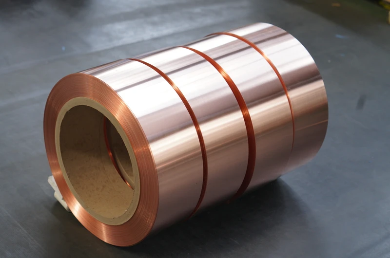
Mechanical Properties and Temper Conditions
The mechanical properties of copper foil for wind power converters are significantly influenced by temper condition (O, 1/2H, H, EH, SH). Annealed (O) copper foil exhibits tensile strength of 220–260 MPa and elongation after fracture of 35–55%, rendering it suitable for deep-drawing and complex-shape forming. Half-hard (1/2H) copper foil displays tensile strength of 250–310 MPa and elongation of 15–30%, making it appropriate for moderate-complexity forming and winding operations. Hard (H) copper foil possesses tensile strength of 290–370 MPa and elongation of 4–10%, and is commonly used for busbars and connecting strips.
Elastic modulus, yield strength, fatigue limit, and fracture toughness constitute the core metrics for evaluating mechanical durability of copper foil windings. During operation, wind power converters are subjected to multiple concurrent mechanical stresses: nacelle vibration (5–200 Hz, 1–15 g), low-frequency cyclic loading induced by wind shear (0.1–2 Hz, 10⁴–10⁶ cycles), thermal cycling (−40°C to +70°C, 1000–3000 cycles), and electromagnetic forces inducing high-frequency vibration (1 kHz–50 kHz, corresponding to switching frequency). The fatigue limit of copper foil is typically 25–35% of its tensile strength; fatigue life prediction during design must therefore incorporate S–N curve analysis and Goodman–Smith correction.
Copper foil thickness directly influences both winding geometry and electrical performance. Standard thickness ranges from 0.05–0.50 mm, with widths spanning 10–600 mm. In wind power converters, LCL filter reactors commonly utilize copper foil of 0.20–0.35 mm thickness and 200–600 mm width; Boost boost inductors typically employ 0.10–0.25 mm thickness and 50–200 mm width; and DC-Link busbars generally require 0.30–0.50 mm thickness and 300–500 mm width.
Critical Performance Indicator System
Electrical Conductivity and Skin Effect
The electrical conductivity of copper foil is defined by the International Annealed Copper Standard (IACS). The volume resistivity of C11000 electrolytic tough pitch copper at 20 °C does not exceed 1.7241×10⁻⁸ Ω·m, corresponding to 100% IACS conductivity. C10100 oxygen-free copper achieves up to 101% IACS conductivity. Within the converter operating temperature range (−40 °C to +155 °C), copper resistivity increases linearly with temperature, exhibiting a temperature coefficient of 0.00393/°C (referenced to 20 °C).
The skin effect constitutes a critical design constraint for high-frequency copper foil windings. At a switching frequency of 10 kHz, the skin depth in copper is approximately 0.66 mm; at 50 kHz, it decreases to 0.29 mm; and in 100 kHz SiC-based converters, the skin depth is merely 0.21 mm. This implies that when copper foil thickness exceeds twice the skin depth, current flows predominantly within the surface layer, rendering the inner copper volume ineffective—thereby increasing winding losses and mass.
Wind power converter (WPC) copper foil windings commonly adopt the following strategies to mitigate skin effect: (i) selecting copper foil thicknesses approximating twice the skin depth (e.g., 0.30–0.50 mm for 10 kHz, 0.10–0.20 mm for 50 kHz); (ii) employing parallel multiple thin copper foils (e.g., ten strands of 0.05 mm foil), with insulating interlayers to suppress eddy currents; and (iii) utilizing Litz wire construction, wherein individual strand diameters remain below twice the skin depth.
Thermal Conductivity and Temperature Rise Control
The thermal conductivity of WPC copper foil windings directly governs their current-carrying capacity and service life. Copper exhibits a thermal conductivity of 391–401 W/(m·K), which is 1.7 times that of aluminum and over 50 times that of steel. The high thermal conductivity of copper foil enables efficient conduction of heat generated in windings of inductors, reactors, and MFTs to the core, insulation layers, and heat sinks.
Under full-load operation of WPCs, winding temperature rise results from combined contributions of copper loss, core loss, insulation loss, and ambient temperature. F-class (155 °C) and H-class (180 °C) insulation systems represent the industry standard. Winding temperature rise limits are typically specified as 90 K (resistance method) or 110 K (thermocouple method), corresponding to rated current densities of 5–8 A/mm² for 690 V low-voltage converters, 4–6 A/mm² for 3300 V medium-voltage converters, and 3–5 A/mm² for medium-voltage converters rated above 10 kV.
Thermal dissipation pathways for copper foil windings include: (i) intra-winding conduction (copper → insulation layer); (ii) natural convection from winding surfaces (insulation surface → ambient air); (iii) forced-air cooling (nacelle fans) or liquid cooling (heat sinks); (iv) thermal radiation from elevated-temperature surfaces; and (v) conduction through the core and metallic structural components. Offshore WPCs frequently employ liquid cooling, where copper foil windings interface with water-cooled plates via thermally conductive greases or pads, achieving thermal resistance control within 0.05–0.15 K/W.
Mechanical Strength and Vibration Durability
Mechanical strength requirements for WPC copper foil windings encompass tensile strength, yield strength, elongation after fracture, bending fatigue, and torsional fatigue. Under nacelle vibration conditions, copper foil windings must withstand random vibration with accelerations of 1–15 g across a frequency range of 5–200 Hz, complying with vibration test standards IEC 60068-2-6 and IEC 61373.
The winding fabrication process—including flat winding, disc winding, and foil winding—significantly influences mechanical performance. Flat-wound copper foil windings utilize continuous helical winding of copper strip, with interlayer insulation provided by paper or polymer films. This configuration offers compact geometry, favorable thermal dissipation, and uniform current distribution; however, special end-turn treatment is required to prevent electric field concentration. Disc winding involves cutting copper foil into annular discs followed by stacking, suitable for high-current busbars and interconnects. Foil winding employs wide-format copper foil wound directly without cutting—achieving highest manufacturing efficiency—but width is constrained by core window dimensions.
Winding clamping and anti-loosening measures constitute key determinants of vibration durability. Common techniques include: interlayer bonding with epoxy or polyester resins; end-turn encapsulation or vacuum pressure impregnation (VPI) with epoxy; global potting; pre-stressed winding processes; and elastic spacer insertion between windings and cores. For offshore WPCs and high-vibration nacelle environments, windings are typically required to pass IEC 61373 vibration testing (5–200 Hz, 10⁹ cycles).
Solderability and Interconnection Processes
Interconnection of WPC copper foil windings to external circuits primarily employs resistance welding, laser welding, ultrasonic welding, tin-based brazing, and direct copper–copper diffusion bonding.
Resistance welding utilizes Joule heating generated by high-current passage across copper foil contact interfaces, with weld durations of 0.1–2 s, suitable for copper foil thicknesses of 0.10–0.50 mm interfaced with copper or aluminum terminals. Laser welding employs fiber or semiconductor lasers (1–4 kW output power) at travel speeds of 1–5 m/min, yielding minimal heat-affected zones and enabling precision interconnections. Ultrasonic welding achieves solid-state bonding between copper foil and terminals via 20–40 kHz ultrasonic vibration under applied pressure, eliminating the need for flux—particularly advantageous for Al–Cu dissimilar-metal joints.
Tin-based brazing utilizes Sn–Ag–Cu or Sn–Pb alloy filler metals at soldering temperatures of 230–280 °C, appropriate for large-format copper busbars and terminals. Direct copper–copper diffusion bonding is performed at 800–900 °C under high vacuum or reducing atmospheres, producing metallurgical bonds with strength approaching that of the base material—though process complexity and cost remain high.
Al–Cu dissimilar-metal interconnection represents a prevalent technological challenge in WPCs. The Al–Cu interface tends to form brittle intermetallic compounds (IMCs)—including Al₂Cu, AlCu, and Al₄Cu₉—during long-term operation, resulting in increased contact resistance and degraded mechanical integrity. Mitigation strategies include: nickel interlayers (Ni barrier layers, 1–5 μm thick); pre-plated nickel copper foil; substitution of tin-based brazing with ultrasonic Al–Cu welding; silver-plated copper foil; and utilization of copper–aluminum clad foil (Cu–Al clad foil).
Typical Application Scenarios
LCL Filter Reactors
The LCL filter is the core grid-side filtering component of wind power converters, designed to suppress harmonic currents injected into the grid at the converter switching frequency and its harmonics, thereby reducing current total harmonic distortion (THD). An LCL filter consists of a converter-side inductor (L₁), a grid-side inductor (L₂), and a filter capacitor (C). The inductance values of L₁ and L₂ typically range from 0.1–3.0 mH, depending on the converter power rating (500 kW–10 MW).
Copper foil windings are primarily employed in wound-core reactors for LCL filters. Common core materials include electrical steel laminations (thickness: 0.20–0.35 mm), amorphous alloys (e.g., Metglas 2605SA1), and nanocrystalline alloys (e.g., Finemet). Electrical steel cores are suitable for low-frequency switching (<1 kHz); amorphous alloys are appropriate for medium-frequency switching (5–20 kHz); and nanocrystalline alloys are optimal for high-frequency switching (20–50 kHz).
The advantages of copper foil windings are particularly pronounced in LCL filter reactors: fill factor reaches 0.75–0.85 (compared to only 0.40–0.55 for enameled round wire), thermal dissipation area is large, hot-spot formation is minimized, and copper losses are reduced by 15–25%. Typical copper foil thicknesses range from 0.20–0.35 mm, widths from 50–400 mm, and configurations include single-layer or multi-layer parallel arrangements. Winding ends are insulated and mechanically reinforced via epoxy casting or vacuum pressure impregnation (VPI).
Boost Inductors and DC-Link Busbars
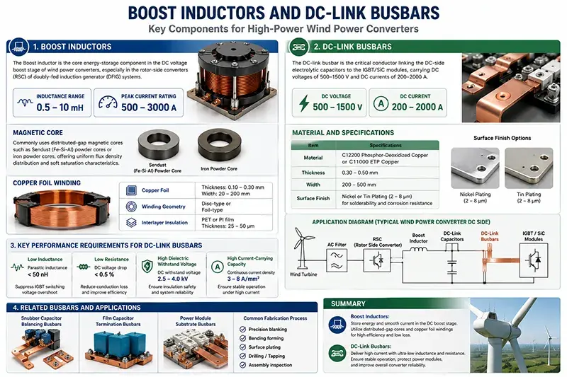
The Boost inductor serves as the core energy-storage component in the DC voltage boost stage of wind power converters, especially in rotor-side converters (RSC) of doubly-fed induction generator (DFIG) systems. Its inductance ranges from 0.5–10 mH, with peak current ratings of 500–3000 A.
Boost inductors commonly employ distributed-gap magnetic cores such as Sendust (Fe-Si-Al) powder cores or iron powder cores, offering uniform flux density distribution and soft saturation characteristics. Copper foil windings use foils of thickness 0.10–0.30 mm and width 20–200 mm, configured in disc-type or foil-type winding geometries; interlayer insulation employs PET or PI films of thickness 25–50 μm.
The DC-link busbar is the critical conductor linking the DC-side electrolytic capacitors to the IGBT/SiC modules, carrying DC voltages of 500–1500 V and DC currents of 200–2000 A. DC-link busbars are typically fabricated from C12200 phosphor-deoxidized copper or C11000 electrolytic tough pitch (ETP) copper, with thicknesses of 0.30–0.50 mm and widths of 200–500 mm. Surface finishes include nickel or tin plating (2–8 μm thick) to enhance solderability and corrosion resistance.
Key performance requirements for DC-link busbars include: low inductance (parasitic inductance < 50 nH, to suppress IGBT switching voltage overshoot), low resistance (DC voltage drop < 0.5%), high dielectric withstand voltage (DC withstand voltage: 2.5–4.0 kV), and high current-carrying capacity (continuous current density: 3–8 A/mm²). Snubber capacitor balancing busbars, film capacitor termination busbars, and power module substrate busbars adopt analogous fabrication processes.
IGBT/SiC Module DBC/AMB Substrates
IGBT (Insulated Gate Bipolar Transistor) and SiC (Silicon Carbide MOSFET) power modules constitute the core power conversion elements of wind power converters. Internally, these modules commonly utilize Direct Bonded Copper (DBC) or Active Metal Brazing (AMB) ceramic substrate architectures: ceramic layers (Al₂O₃, AlN, Si₃N₄) with thicknesses of 0.25–0.63 mm, and copper layers of 0.20–0.50 mm thickness on both top and bottom surfaces, bonded to the ceramic via high-temperature co-firing or active brazing.
The choice of ceramic material in DBC substrates directly governs module thermal and mechanical performance: Al₂O₃ (alumina) offers the lowest cost and thermal conductivity of 24–30 W/(m·K), making it the mainstream choice for medium- and low-voltage modules; AlN (aluminum nitride) provides superior thermal conductivity of 170–180 W/(m·K), rendering it the preferred option for high-power-density modules; Si₃N₄ (silicon nitride) exhibits exceptional flexural strength (700–900 MPa) and outstanding thermal shock resistance, rendering it ideal for wind power converters subjected to high vibration and severe thermal cycling.
Copper layer thickness in DBC/AMB substrates must balance current-carrying capability, thermal spreading efficiency, and mechanical stress. Typical thickness combinations include: Al₂O₃ 0.38 mm + Cu 0.20/0.30 mm; AlN 0.40 mm + Cu 0.20/0.30 mm; Si₃N₄ 0.32 mm + Cu 0.25/0.30 mm. AMB substrates (e.g., Si₃N₄–AMB) employ Ag-based or Cu–Sn-based active braze alloys, enabling oxide-free copper–ceramic bonding at temperatures of 700–800 °C, with bond strengths of 200–300 MPa.
The top copper foil layer of power modules functions as the chip soldering and wire-bonding region, with thicknesses of 0.10–0.30 mm. Bonding processes include aluminum ultrasonic wire bonding (200–300 μm Al wire) or copper ribbon bonding (flexible copper ribbons, width 1–5 mm). For wind power converter IGBT modules, the top copper foil trace layer features a composite plating of nickel (5–10 μm) followed by silver (1–3 μm) to enhance oxidation resistance and solderability.
Medium-Frequency Isolation Transformers and Common-Mode/Differential-Mode Inductors
The medium-frequency transformer (MFT) is a critical isolation component in solid-state transformers (SST) and medium-voltage wind power converters, operating at frequencies of 1–50 kHz and voltage levels of 3.3 kV–35 kV. Compared to line-frequency transformers, MFTs offer significant advantages in compactness, weight reduction, and efficiency; however, their copper foil windings suffer pronounced skin and proximity effects under high-frequency operation.
MFT copper foil windings typically employ foils of thickness 0.05–0.20 mm in multi-strand parallel configurations (e.g., 20 strands of 0.05 mm foil) or Litz wire structures. Winding insulation utilizes PI film or mica paper, with thicknesses of 0.10–0.50 mm, selected according to voltage class. Core materials for MFTs include nanocrystalline alloys, Fe–Si alloys, and amorphous alloys; core cross-sectional design is tightly coupled with winding geometry.
Common-mode (CM) chokes and differential-mode (DM) chokes are key components of electromagnetic interference (EMI) filters in wind power converters. CM chokes employ bifilar winding or copper foil winding configurations to suppress common-mode interference currents (spanning tens of kHz to tens of MHz). DM chokes utilize single-wire or copper foil winding configurations to suppress differential-mode interference currents.
Copper foil windings for CM/DM chokes typically feature thicknesses of 0.05–0.20 mm and widths of 5–50 mm, with core materials comprising high-permeability ferrites or nanocrystalline alloys. Winding ends are encapsulated using epoxy or polyurethane potting compounds to improve moisture resistance and mechanical robustness. Strict symmetry between the two windings of a CM choke is mandatory; asymmetry induces unbalanced currents and exacerbates EMI issues.
Manufacturing Processes
Rolling-Annealing and Continuous Extrusion
The manufacturing processes for copper foil used in wind power converters (WPC) are primarily categorized into two types: the electrolytic-rolling-annealing (RA) process and the continuous extrusion process.
The electrolytic-rolling-annealing (RA) process employs electrolytic copper as raw material and fabricates copper foil with thicknesses ranging from 0.05 mm to 0.50 mm via a sequence of operations: melting and casting → hot rolling → cold rolling → intermediate annealing → final cold rolling. Intermediate annealing is conducted at 400–600°C for 1–4 hours, while final annealing is performed at 350–500°C. The annealing parameters critically determine the grain size (10–100 μm), mechanical properties (tensile strength and elongation), and electrical conductivity (expressed in %IACS) of the copper foil.
The Conform continuous extrusion process utilizes copper rod or wire as feedstock and directly forms copper foil through friction-driven feeding and die extrusion. It is particularly suited for medium- and small-size copper foil with thicknesses of 0.10–0.30 mm and widths of 50–300 mm. Advantages of this process include low energy consumption, high material utilization efficiency, and excellent dimensional accuracy—making it a widely adopted method for WPC copper foil production.
The continuous casting and rolling (CCR) process employs electrolytic copper plates as input material. Copper plates are continuously cast using a continuous caster and subsequently rolled into copper foil via multi-stand tandem rolling mills. Owing to its high production capacity and low specific energy consumption, CCR is the dominant industrial process for large-scale manufacturing of copper foil with thicknesses of 0.20–0.50 mm.
The microstructure of copper foil—including grain size and crystallographic texture—directly governs both its mechanical and electrical performance. As-annealed copper foil exhibits an equiaxed grain structure, characterized by low tensile strength and high elongation; in contrast, cold-rolled copper foil displays a fibrous microstructure associated with high tensile strength and low elongation. For WPC copper foil windings, the material is typically specified in the fully annealed (O) or half-hard (1/2H) temper state to balance formability and mechanical robustness.
Surface Treatment and Insulation Coating
Surface treatment of copper foil involves a modular combination of sequential steps: cleaning (alkaline degreasing followed by acid pickling and neutralization) → micro-etching (to increase surface roughness, Ra = 0.3–1.5 μm) → electroless or electroplating (with Ni, Sn, or Ag, thickness 1–10 μm) → passivation (using benzotriazole [BTA] or chromate-based agents, thickness 0.05–0.5 μm) → insulation coating (with PET, PI, epoxy resin, or Parylene).
Parylene (poly-para-xylylene) is a polymer film deposited via chemical vapor deposition (CVD), offering exceptional uniformity and extremely low pinhole density (< 1/cm²) at thicknesses of 1–50 μm. These attributes render Parylene especially suitable for insulation of high-frequency, high-power-density copper foil windings. Parylene C and Parylene N are the predominant commercial grades.
Vacuum pressure impregnation (VPI) with epoxy resin constitutes a critical insulation process for integrated WPC copper foil windings. The VPI process sequence comprises: pre-baking (80–120°C, 2–6 h) → vacuum degassing (< 100 Pa, 2–4 h) → pressurized impregnation (0.2–0.5 MPa, 4–8 h) → drip draining (0.5–2 h) → thermal curing (150–180°C, 6–12 h). Common VPI resin systems include epoxy–anhydride, epoxy–amine, and polyester formulations.
Slitting, Stamping, and Winding Formation
Slitting of copper foil is performed using precision slitting machines to subdivide wide-width foil (500–1200 mm) into narrow strips (10–600 mm). Tolerances require width deviation within ±0.10 mm, burr height < 0.02 mm, and edge camber < 0.5 mm/m. Cutting tools employ cemented carbide or diamond-coated blades, with tool lifetimes ranging from 50 to 200 km.
Stamping of copper foil is executed on high-speed precision stamping presses equipped with multi-station progressive dies, enabling fabrication of complex geometries such as L-, T-, and U-shaped profiles, as well as busbars. Typical stamping speeds range from 100 to 1000 strokes per minute (SPM), with dimensional accuracy maintained within ±0.05 mm. While highly efficient for mass production, stamping entails high tooling costs and extended changeover times.
Winding formation of copper foil is carried out using automated winding machines or foil winding machines. In foil winding machines, copper foil is fed under controlled tension, interleaved with insulating layers, and wound onto a rotating mandrel. Process parameters include winding tension of 5–50 N, winding speed of 5–30 m/min, and turn-to-turn positioning accuracy of ±0.5 turns. Winding terminations are implemented either via copper foil lead-outs or copper braided straps.
Specialized winding configurations employed in WPC copper foil windings include helical flat winding, disc-type winding, foil winding, continuous foil tape forming, and hybrid winding (copper foil combined with Litz wire). Each configuration presents distinct advantages and trade-offs; selection must be guided by application-specific requirements. Helical flat winding is preferred for high-voltage applications; disc-type winding suits high-current designs; and foil winding enables standardized, repeatable manufacturing.
Quality Inspection and Reliability Verification
Performance Testing Standards
Performance testing of copper foil windings for Wind Power Converters (WPC) encompasses five categories: electrical conductivity, insulation performance, mechanical properties, thermal performance, and environmental adaptability.
Electrical conductivity testing includes: volume resistivity (four-terminal method, ASTM B193), conductivity (% IACS), contact resistance (four-wire method, IEC 61230), and temperature coefficient of direct-current resistance (20 °C to 200 °C).
Insulation performance testing includes: dielectric withstand voltage (AC/DC, IEC 60243, ASTM D149), dielectric loss tangent (tan δ, ASTM D150), partial discharge inception voltage (PDIV) and extinction voltage (PDEV, IEC 60270), and insulation resistance (IEC 60093).
Mechanical property testing includes: tensile strength and yield strength (ASTM E8), elongation after fracture (ASTM E8), hardness (HV, ASTM E384), bending fatigue (ASTM E796), and peel strength (IPC TM-650 2.4.8).
Thermal performance testing includes: thermal conductivity (ASTM E1461 flash method), specific heat capacity (DSC), coefficient of thermal expansion (TMA), thermal resistance (IEC 60851), and thermal aging (IEC 60216 Arrhenius model).
Environmental adaptability testing includes: temperature cycling (IEC 60068-2-14, −40 °C to +125 °C, 1,000 cycles), damp heat cycling (IEC 60068-2-30, 40 °C/95% RH, 96–1,000 hours), salt mist exposure (IEC 60068-2-52, 5% NaCl, 30–90 days), vibration (IEC 60068-2-6, 5–200 Hz, 1–15 g), and shock (IEC 60068-2-27, 50 g/11 ms).
Wind Power–Grade Standard Compliance
Core standards applicable to copper foil windings for WPC include:
IEC 61400-1 Wind turbines — Part 1: Design requirements specifies design loads and safety requirements for wind turbine systems under varying wind conditions, temperatures, altitudes, and environmental conditions; it serves as the overarching framework governing mechanical strength and temperature-rise limits for copper foil windings in WPC. The fourth edition of IEC 61400-1 (2019) introduces design requirements for offshore wind power, extreme offshore wind conditions, and typhoon operating conditions.
IEC 62116 Test specification of islanding prevention measures for grid-connected photovoltaic inverters defines anti-islanding protection requirements for WPC under abnormal grid conditions. IEC 61683 Photovoltaic systems — Power conditioners — Procedure for measuring efficiency specifies efficiency measurement procedures for power converters (partially applicable to WPC). The IEC 61800 series—particularly IEC 61800-1, IEC 61800-2, and IEC 61800-4—specifies general requirements for adjustable speed electrical power drive systems, along with technical specifications for low-voltage and medium-voltage converters.
GB/T 20320 Technical requirements for grid connection of wind turbine generators stipulates grid-connection requirements for wind power generation in China, including Low-Voltage Ride-Through (LVRT), High-Voltage Ride-Through (HVRT), frequency adaptation range, reactive power regulation capability, and harmonic emission limits. UL 1741 Standard for Inverters, Converters, Controllers and Interconnection System Equipment for Use With Distributed Energy Resources applies to certification of WPC intended for the North American market. IEEE 1547 Standard for Interconnection and Interoperability of Distributed Energy Resources with Associated Electric Power Systems Interfaces defines technical interconnection requirements for distributed energy resources.
UL 94 Standard for Safety of Flammability of Plastic Materials for Parts in Devices and Appliances establishes flammability classification requirements for insulating encapsulation materials used in copper foil windings for WPC; V-0 rating is commonly specified. IEC 60695-2-11 and IEC 60695-2-12 specify glow-wire test methods and temperature requirements. GB/T 2408 Plastics — Determination of burning behaviour — Horizontal and vertical flame tests is the corresponding Chinese national standard.
Long-Term Reliability and Lifetime Prediction
Long-term reliability of copper foil windings for WPC is influenced by multiple factors: insulation aging induced by thermal cycling (Arrhenius model), winding loosening and fatigue caused by mechanical vibration, insulation breakdown due to humidity and salt mist exposure, and winding deformation and copper foil degradation resulting from prolonged overload operation. Lifetime prediction methodologies include:
Arrhenius model for insulation lifetime prediction:
Lifetime L = L₀ × exp(Eₐ/(k × T)), where Eₐ denotes activation energy (80–120 kJ/mol for epoxy resin), k is the Boltzmann constant, and T is absolute temperature. Copper foil winding insulation is designed for a service life of 20,000 hours at F-class (155 °C) and H-class (180 °C) temperature ratings.
Miner’s linear cumulative damage rule for mechanical fatigue lifetime prediction: Σ(nᵢ/Nᵢ) < 1, where nᵢ represents the number of actual cycles at a given stress level and Nᵢ denotes the corresponding number of cycles to failure derived from the S–N curve. Under nacelle vibration conditions, copper foil windings must pass vibration durability testing for 10⁹ cycles.
Failure Mode and Effects Analysis (FMEA) systematically identifies failure modes of copper foil windings for WPC—including insulation breakdown, winding loosening, copper foil overheating, terminal fracture, and vibration-induced fatigue cracking. Each failure mode is assessed for severity (S), occurrence (O), and detection (D), and a Risk Priority Number (RPN) is calculated.
Maintenance strategies for copper foil windings in WPC include periodic infrared thermographic inspection (to identify hotspots), insulation resistance testing (to detect moisture ingress), vibration spectrum analysis (to detect loosening), and oil analysis (to monitor transformer oil condition). For offshore wind applications, maintenance windows are constrained by weather and sea conditions; therefore, condition-based predictive maintenance (CBM) and digital twin technologies are required.
Conclusion
Copper foil windings for Wind Power Converters (WPC) represent a critical material enabling high-efficiency, high-power-density, and high-reliability electrical energy conversion in wind turbine systems. Materially, they are predominantly based on three copper alloy systems: C11000 electrolytic tough pitch copper, C10100/C10200 oxygen-free copper, and C12200 phosphor-deoxidized copper. Performance requirements include electrical conductivity exceeding 100% IACS, thermal conductivity exceeding 391 W/(m·K), temperature resistance compatible with F-class and H-class insulation systems, and vibration durability meeting wind power-specific specifications. Application scope encompasses four major subcomponent families: LCL filter reactors, Boost boost inductors and DC-Link busbars, DBC/AMB substrates for IGBT/SiC modules, and medium-frequency isolation transformers (MFT) as well as common-mode (CM) and differential-mode (DM) inductors. Manufacturing processes include electrolytic rolling and annealing, continuous extrusion, continuous casting and rolling, surface insulation coating, slitting and stamping, and winding formation. Verification must comply strictly with core international and national standards, including IEC 61400-1, IEC 62116, IEC 61683, IEC 61800, GB/T 20320, UL 1741, IEEE 1547, and IEC 60068.
Future development trends of copper foil windings for WPC will evolve along three principal directions. First, the penetration rate of SiC devices in WPCs will continue to increase, driving switching frequencies from the current mainstream range of 3–10 kHz upward toward 20–50 kHz and beyond—thereby imposing stricter requirements on skin-effect suppression and high-frequency loss control in copper foil windings. Second, the sustained growth in offshore wind installed capacity will propel WPCs toward higher power density and enhanced environmental robustness; consequently, corrosion resistance, water resistance, and anti-salt-fog performance of copper foil windings must be further improved. Third, the maturation of digital twin and lifetime prediction technologies will shift maintenance strategies for copper foil windings from time-based maintenance to predictive maintenance—thereby enhancing the full-life-cycle reliability and economic viability of wind turbine systems.