


The On-Board Charger (OBC) is a core electrical component of new energy vehicles (NEVs), responsible for converting AC grid power into DC power to charge the battery. Copper foil, as the core conductive material in OBCs for magnetic components, power buses, PCB wiring, and EMI shielding, plays an irreplaceable role in key components such as PFC inductors, LLC resonant inductors, isolation transformers, output filters, and drive circuits. With the rapid development of 800V high-voltage platforms, bidirectional OBCs (V2G/V2X), and wide-bandgap semiconductors (SiC/GaN) in new energy vehicles, the application requirements and technical demands of copper foil in OBCs have significantly increased. This article systematically describes the basic architecture of OBCs, the key role of copper foil, a comparison between copper foil and aluminum foil, copper foil types and specifications, manufacturing processes, typical applications, key performance requirements, and selection decisions.
Basic Architecture and Working Principle of Vehicle OBC
An on-board charger (OBC) is a power electronic device that converts alternating current (AC) from the power grid into direct current (DC) required by the battery. It is one of the core electrical components of new energy vehicles. The OBC connects to the vehicle interior via a ground-based AC charging station or AC charging port, converting AC 220V/380V input to DC 200-800V output for slow or fast charging of the battery.
Based on power rating, On-Board Chargers (OBCs) mainly include: 3.3kW (home slow charging, single-phase AC 220V/16A), 6.6kW (home fast charging, single-phase AC 220V/32A or dual-phase AC 380V/16A), 7kW (mainstream in Europe, single-phase AC 220V/32A), 11kW (three-phase AC 380V/16A, high-end European models), and 22kW (three-phase AC 380V/32A, high-end luxury models). The power rating of the OBC for new energy vehicles is closely related to the vehicle’s positioning, battery capacity, and charging time requirements.
According to electrical architecture classification, the core architecture of OBC consists of two stages of AC-DC converters: the first stage is a PFC (Power Factor Correction) rectifier, which converts the AC input to the DC bus voltage (typically 400V), achieving unity power factor (PF≥0.99) and harmonic current suppression (meeting IEEE 519 and GB/T 14549 standards); the second stage is an isolated DC-DC converter, which converts the DC bus voltage to the DC high voltage (200-800V) required for battery charging, and achieves electrical isolation through a high-frequency transformer.
In terms of PFC topology, the mainstream PFC topologies for OBCs include: traditional bridge PFC (Boost PFC), totem-pole PFC (bridgeless PFC), interleaved PFC, and bridgeless PFC. The application of SiC/GaN wide-bandgap semiconductors has made totem-pole PFC the mainstream solution for high-power OBCs (11kW/22kW), with switching frequencies of 65-200 kHz and efficiencies reaching 98.5-99%.
Regarding isolated DC-DC topologies, mainstream isolated DC-DC topologies for OBCs include: LLC resonant converters, phase-shifted full-bridges (PSFBs), and dual active bridges (DABs, used in bidirectional OBCs). LLC resonant converters are the mainstream solution for unidirectional OBCs, with switching frequencies of 100-500 kHz and efficiencies reaching 96-98%. DABs are the mainstream solution for bidirectional OBCs (V2G).
In terms of magnetic components, OBCs contain a variety of magnetic components: PFC inductors, LLC resonant inductors, isolation transformers, output filter inductors, common mode inductors (CM chokes), and gate drive transformers. These magnetic components are the core of OBC performance. Their winding materials are primarily copper foil, with some using enameled round copper wire, Litz wire, and flat enameled copper wire.
Regarding auxiliary power, the OBC also includes auxiliary power modules (such as a flyback converter) that convert the DC bus to 12V/15V/24V auxiliary power to power control circuits, drive circuits, relays, and sensors. The auxiliary power supply has a switching frequency of 50-300 kHz and uses small magnetic cores and enameled round copper wire windings.
In terms of control and communication, the OBC is equipped with an MCU/DSP controller (such as TI C2000 or Infineon Aurix), a CAN/LIN communication interface, a CCP/UDS diagnostic protocol, and the ISO 15118 charging communication protocol. The OBC communicates in real time with the BMS (battery management system) and VCU (vehicle control unit) via the CAN bus to achieve dynamic adjustment of charging power, overcurrent and overvoltage protection, temperature monitoring, and fault diagnosis.
Key Functions of Copper Foil in OBC
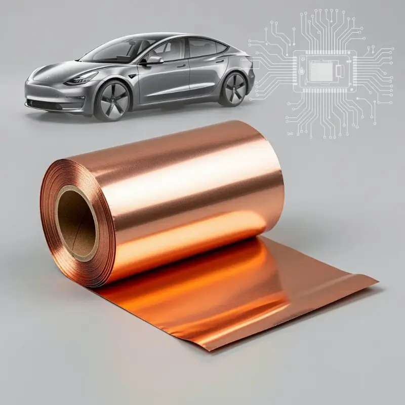
Copper foil plays several key roles in the on-board charger (OBC): magnetic component winding, power busbar, PCB wiring, EMI shielding, heat dissipation, and grounding protection.
In terms of magnetic component windings, copper foil is the core winding material for PFC inductors, LLC resonant inductors, isolation transformers, and output filter inductors in OBCs. Compared to traditional enameled round copper wire, copper foil windings have significant advantages: larger conductor cross-sectional area (reducing DC resistance DCR), lower skin effect losses (high-frequency current flows on the conductor surface, and the flat structure of copper foil provides a larger surface area-to-volume ratio), better heat dissipation (the flat structure of copper foil increases the heat dissipation area), higher space utilization (copper foil is tightly stacked, with a fill factor of 70-85%, far higher than the 40-60% of round wire), and lower leakage inductance (flat windings reduce magnetic field leakage). In LLC resonant converters (switching frequencies 100-500 kHz), the skin effect advantage of copper foil windings is particularly pronounced, significantly reducing AC resistance (ACR) and switching losses.
Regarding power buses, the DC bus of the OBC (connecting the PFC output and DC-DC input) needs to carry high current (peak 30-100A), typically employing a laminated copper busbar or a multi-layered copper busbar structure. The advantages of copper busbars include: low inductance (multi-layer lamination reduces parasitic inductance and lowers switching overshoot), low resistance (high conductivity reduces conduction losses), good heat dissipation (flat structure dissipates heat quickly), and compact space (multi-layer lamination reduces volume). In SiC/GaN high-frequency applications, the low inductance characteristics of copper busbars are crucial for reducing switching overshoot and protecting semiconductor devices.
In terms of PCB routing, OBC’s PCBs (printed circuit boards) use electrolytic copper foil as the conductive layer. OBC PCBs typically employ multilayer boards (4-8 layers), including: a signal layer (0.035-0.070mm copper foil), a power layer (0.070-0.210mm thick copper foil), and a ground layer (0.035-0.070mm copper foil). High-voltage, high-current power paths utilize thick copper foil (2-4 oz, 0.070-0.140mm) or ultra-thick copper foil (6-10 oz, 0.210-0.350mm).
Regarding EMI shielding, the high-frequency switching (65-500 kHz) of the PFC and DC-DC converters in the OBC generates a significant amount of electromagnetic interference (EMI), including common-mode interference (CM) and differential-mode interference (DM). Copper foil shielding layers (such as copper foil Mylar tape, copper foil + PI composite shielding) can effectively suppress EMI radiation and conduction. The shielding structure of the OBC typically employs: copper foil wrapping around the magnetic core (reducing magnetic field radiation from the core), copper foil shielding of sensitive signals on the PCB (protecting control signals), and copper foil outer shell shielding (overall EMC shielding). The EMC design of the OBC must comply with automotive EMC standards such as CISPR 25, ISO 11452, and ISO 7637.
In terms of heat dissipation, the high thermal conductivity of copper foil (approximately 400 W/m·K, about 1.7 times that of aluminum) makes it an excellent heat dissipation material in OBCs. The copper foil windings can directly and closely contact the magnetic core and heat sink, conducting heat from the magnetic components to the heat sink. In high power density OBCs (>3 kW/L), the heat dissipation performance of the copper foil windings is crucial for ensuring the long-term reliability of the OBC.
For grounding protection, copper foil serves as the connection between the OBC’s ground plane and protective earth (PE), providing a low-impedance fault current return path. The OBC’s grounding design includes: protective earth (PE, connected to the vehicle chassis), functional earth (signal ground), and shield earth (single-point or multi-point grounding of the shield). The low resistance and good conductivity of the copper foil ensure the reliability of the grounding system.
Comparison of Copper Foil and Aluminum Foil
Copper foil and aluminum foil are the two major categories of metal foil materials in OBC, and they differ significantly in terms of weight, cost, electrical conductivity, thermal conductivity, mechanical properties, processability, and application scenarios.
In terms of weight, copper has a density of 8.96 g/cm³, while aluminum has a density of 2.70 g/cm³, making copper approximately 3.3 times heavier than aluminum. With the trend towards lightweighting in new energy vehicles, aluminum foil offers a significant weight advantage over copper foil. The total weight of copper foil inside an OBC can reach 0.5-3 kg, and replacing some copper foil with aluminum foil (such as in non-critical low-current paths) can reduce weight by 50-70%. However, core high-current-density components of the OBC (magnetic component windings, power busbars) still primarily use copper foil because copper’s high conductivity allows for a significant reduction in foil thickness (copper foil thickness is only 60% of aluminum foil at the same current), resulting in limited overall weight reduction.
In terms of cost, the market price of copper is approximately 3-4 times that of aluminum (based on 2024 data: copper approximately 60-80 RMB/kg, aluminum approximately 18-25 RMB/kg). Copper foil is significantly more expensive than aluminum foil. However, the core performance requirements of OBCs (high efficiency, low loss, high power density) make copper foil irreplaceable in key components such as PFC inductors, LLC resonant inductors, and isolation transformers. Aluminum foil can be used in non-critical components of OBCs (such as housing shielding, low-current PCB wiring, and auxiliary heat dissipation) to reduce costs.
In terms of conductivity, copper has a conductivity of 100% IACS, while aluminum has a conductivity of approximately 61% IACS, indicating that copper’s conductivity is significantly superior to aluminum’s. For the same cross-sectional area, the resistance of copper foil is approximately 60% of that of aluminum foil. In the magnetic components of an OBC, winding resistance directly affects copper loss, which is directly proportional to resistance. In the design of high-efficiency OBCs (>96%), the low resistance of the copper foil is crucial for achieving high efficiency.
In terms of thermal conductivity, copper has a thermal conductivity of approximately 400 W/m·K, while aluminum has a thermal conductivity of approximately 237 W/m·K, indicating that copper has better thermal conductivity than aluminum. In the high power density design of OBCs, the high thermal conductivity of copper foil helps to quickly conduct heat from magnetic components and power devices to the heat dissipation substrate, reducing junction temperature and improving reliability.
In terms of mechanical properties, copper has a tensile strength of 220-400 MPa, while aluminum has a tensile strength of 80-150 MPa (pure aluminum, O state). Copper has significantly better mechanical strength than aluminum, but aluminum has better flexibility. Copper foil is more resistant to bending fatigue, but it is more prone to cracking under large bending radii. In small bending radius scenarios of OBC windings (high-frequency transformer windings), rolled and annealed copper foil (RA Copper Foil) has better flexibility than electrolytic copper foil (ED Copper Foil).
In terms of processability, electrolytic copper foil (ED) is typically 0.035-0.210 mm thick, with a single-sided smooth/single-sided rough surface, suitable for PCB applications. Rolled copper foil (RA) is typically 0.01-0.50 mm thick, with a smooth surface on both sides and good flexibility, suitable for magnetic component windings. Aluminum foil has a wider processing thickness range (0.005-0.10 mm) and good ductility, but its thinness results in low strength and susceptibility to breakage.
In terms of application scenarios, copper foil is used in OBCs for: magnetic component windings (PFC inductors/LLC inductors/transformer/filter inductors), power buses, PCB routing (signal/power/ground layers), EMI shielding, and heat dissipation substrates. Aluminum foil is used in OBCs for: housing shielding, auxiliary heat dissipation, low-current PCB routing, and non-critical busbars. Copper foil and aluminum foil are complementary rather than completely substitutive in OBCs.
Regarding connection methods, copper foil can be connected to copper wire using welding (soldering, silver soldering, laser welding), crimping, or wrapping, ensuring reliable connections. Connecting aluminum foil to copper wire requires special processes (ultrasonic welding, crimping, copper-aluminum transition joints), making the connection more difficult. The high reliability requirements of OBCs make copper foil the preferred material for magnetic components and power busbars.
Types and Specifications of Copper Foil
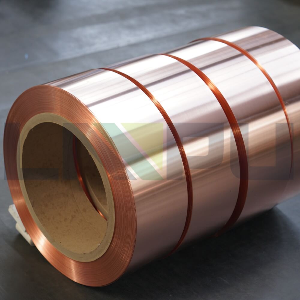
OBC copper foil is classified according to manufacturing process, alloy composition, state, thickness, composite form, and surface treatment.
In terms of manufacturing process, copper foil is divided into two main categories:
Electrodeposited copper foil (ED Copper Foil): Manufactured through an electrolytic deposition process, copper ions are deposited onto a cathode roller to form copper foil. Characteristics of electrodeposited copper foil: single-sided smooth surface (Shiny Side) or single-sided matte surface (Matte Side), with a surface roughness Ra of 0.5-5μm, suitable for lamination with PCB substrates. Typical thickness: 0.035-0.210mm (1-6 oz). The purity of electrodeposited copper foil is ≥99.95%, and its conductivity is ≥100% IACS.
- Rolled Annealed Copper Foil (RA Copper Foil): Manufactured through a rolling process, it is formed by repeatedly cold rolling and annealing electrolytic copper plates or ingots. Characteristics of rolled copper foil: smooth on both sides, no rough surfaces, surface roughness Ra <0.5μm, good flexibility, and high elongation (>30%). Typical thickness: 0.01-0.50mm. The purity of rolled copper foil is ≥99.95%, and the conductivity is ≥100% IACS. RA copper foil is particularly suitable for high-frequency magnetic component windings and flexible applications (FPC flexible boards).
Regarding alloy composition, the copper foil used in OBCs is mainly pure copper (C1100, C1220, etc.) with a purity of ≥99.95%. Some high-strength applications use copper alloy foil (Cu-Be, Cu-Cr-Zr, Cu-Zr, etc.), but these are less commonly used in OBCs.
In terms of annealing state, copper foil is classified into hard (H), half-hard (1/2H), and soft (O) states based on the degree of annealing. Hard copper foil has high strength (tensile strength 350-450 MPa) but low elongation (<5%). Soft copper foil has lower strength (tensile strength 220-300 MPa) but high elongation (>30%). The magnetic component windings of OBCs mainly use soft (O) or half-hard (1/2H) rolled copper foil to ensure bending performance.
In terms of thickness, the thickness of the copper foil directly determines the current carrying capacity, resistance, weight, and cost. Common thicknesses of copper foil for OBCs include:
- 0.010mm (ultra-thin): FPC flexible board, ultra-high frequency – 0.018mm (thin): high frequency transformer winding – 0.035mm (1 oz): PCB standard signal layer – 0.070mm (2 oz): PCB power layer – 0.105mm (3 oz): PCB high current layer – 0.140mm (4 oz): PCB power layer – 0.210mm (6 oz): PCB ultra-high current, busbar – 0.3-0.5mm (thick): power busbar, special applications
Regarding width, the copper foil width is selected according to the requirements of various components in the OBC. Common widths are: 10mm, 15mm, 20mm, 25mm, 30mm, 40mm, 50mm, 60mm, 80mm, 100mm, 150mm, 200mm, 300mm, and 500mm. Standard widths of 20-50mm are used for general magnetic component windings, while widths of 100-500mm are used for busbars and large-size shielding layers.
In terms of composite forms, copper foil can be combined with various insulating materials to form copper-plastic composite tapes, common forms of which include:
- Copper foil + PI polyimide film (temperature resistance -200°C to +260°C, most commonly used) – Copper foil + PET (polyester) film (temperature resistance -40°C to +150°C) – Copper foil + PEN (polyethylene naphthalate) film (temperature resistance -40°C to +180°C) – Copper foil + polyimide + fluoroplastic composite (high temperature resistance, chemical resistance) – Copper foil + ceramic filler (high pressure resistance, high thermal conductivity)
The most commonly used copper foils for OBCs are pure copper foil (RA rolled copper foil) and copper foil + PI composite tape.
In terms of surface treatment, copper foil surface treatments include: untreated copper (with a natural oxide film on the surface), brown oxide treatment (to improve adhesion to insulating materials), tin plating (to improve solderability), nickel plating (to improve temperature and wear resistance), and silver plating (to improve conductivity and corrosion resistance). OBC PCB copper foil is usually treated with brown oxide, while the copper foil windings of magnetic components use untreated copper or tin plating.
Manufacturing Process of Copper Foil
The manufacturing process for copper foil used in OBCs varies depending on the type. The manufacturing processes for electrolytic copper foil and rolled copper foil are as follows:
Manufacturing process of electrolytic copper foil (ED):
- Copper Dissolution: Electrolytic copper or recycled copper is electrolytically dissolved in a copper sulfate solution to form a high-purity copper sulfate electrolyte (Cu²⁺ concentration 50-120 g/L, H₂SO₄ concentration 80-150 g/L). 2. Electrolytic Deposition: In an electrolytic cell, direct current is passed through a lead alloy anode and a titanium roller cathode, and copper ions are deposited on the surface of the cathode roller to form copper foil. Electrolysis parameters: current density 30-80 A/dm², cell temperature 40-60°C, electrolyte circulation and filtration. 3. Continuous Peeling: As the cathode roller rotates, the continuously deposited copper foil is peeled off from the roller surface to form a continuous copper foil strip. 4. Surface Treatment: The surface of the copper foil is roughened (to increase roughness and improve adhesion to the substrate) and subjected to anti-oxidation treatment (passivation or zinc/nickel plating to prevent oxidation and discoloration). 5. Winding: The copper foil strip is wound into standard rolls (PT10-PT50). 6. Slicing: Slice into narrow strips according to the width of specifications.
Manufacturing process of rolled copper foil (RA):
- Melting and Casting: Electrolytic copper is heated to above 1083°C in a smelting furnace and melted, then cast into copper plates or ingots. 2. Hot Rolling: Copper ingots are hot rolled multiple times on a hot rolling mill (bread rolling) to reduce the thickness from 100-200mm to 4-8mm. The hot rolling temperature is 750-950°C. 3. Cold Rolling: The hot-rolled copper strip is cold-rolled multiple times at room temperature to reduce the thickness from 4-8mm to 0.1-0.5mm. Work hardening occurs during the cold rolling process. 4. Intermediate Annealing: Intermediate annealing (400-600°C, holding for 2-8 hours) is performed during the cold rolling process to eliminate work hardening and restore plasticity. 5. Finish Rolling: Cold rolling continues until the target thickness (0.01-0.5mm) is achieved. 6. Annealing: Annealing the finished product (300-500°C) to bring the copper foil to a soft (O) or semi-hard (1/2H) state. 7. Surface Treatment: Cleaning, polishing, and anti-oxidation treatment. 8. Slitting: Slitting to the specified width. 9. Rewinding and Packaging.
Manufacturing process of copper foil composite tape:
- Adhesive Coating: Apply adhesive (acrylate, epoxy resin, polyurethane, etc.) to the PI/PET film and dry it in an oven tunnel. 2. Hot Press Lamination: Lay the copper foil and the adhesive-coated film together using hot press rollers (temperature 100-200°C, pressure 1-5 MPa). 3. Curing: Cure the laminated tape at 40-80°C for 24-72 hours to fully cure the adhesive. 4. Slitting, Winding, and Packaging.
Key quality indicators for copper foil include: purity (≥99.95%), conductivity (≥100% IACS), thickness tolerance (±5% to ±10%), width tolerance (±0.5mm), surface roughness (Ra <0.5μm to 5μm), tensile strength (O temper 220-300 MPa), elongation (O temper >30%), electrical resistance (calculated by thickness), and adhesive strength (peel strength to insulating material ≥5 N/cm).
Applications in PFC Rectifier and Boost Inductor
PFC (Power Factor Correction) is the first stage AC-DC converter in an OBC. Its core functions are: 1) rectifying the AC input to a DC bus voltage; 2) achieving unity power factor (PF≥0.99); and 3) suppressing input current harmonics (meeting IEEE 519 and GB/T 14549 standards). The magnetic components of PFC include the PFC boost inductor and the input filter inductor.
Regarding PFC boost inductors, their operating frequencies are 65-200 kHz (traditional Si-based PFC) or 65-500 kHz (SiC/GaN totem-pole PFC). Inductance values range from 100-2000 μH, with peak currents of 10-50A (3.3kW OBC), 20-80A (6.6kW OBC), and 40-150A (11kW/22kW OBC). The winding material for PFC boost inductors is primarily RA rolled copper foil, with a thickness of 0.05-0.30 mm and a width of 10-50 mm. The advantages of copper foil windings include: low DC resistance (DCR), low AC resistance (ACR), high fill factor (70-85%), and good heat dissipation.
In the field of totem-pole PFC, SiC/GaN wide-bandgap semiconductors have made totem-pole PFC the mainstream solution for 11kW/22kW OBCs. Totem-pole PFC operates at frequencies of 65-200 kHz, and the size and weight of the PFC boost inductor are significantly reduced. The low-loss characteristics of the copper foil winding are key to achieving a high efficiency of 98.5-99% in totem-pole PFC.
Regarding interleaved parallel PFC, interleaved parallel PFC employs two or more parallel Boost PFCs, which can significantly reduce input current ripple, lower switching stress, and increase power density. The inductance value of each path in interleaved PFC is approximately half that of a single path. The winding material of each inductor is still mainly copper foil, but the cross-sectional area of the copper foil can be reduced accordingly.
Regarding the PFC input filter inductors, the EMI filter inductors (CM Choke + DM Choke) at the PFC input terminal use copper foil windings or enameled round copper wire windings. The CM Choke typically uses a toroidal core, with copper foil or enameled wire windings to suppress common-mode interference (10 kHz-30 MHz). The DM Choke typically uses an iron powder core or an iron-silicon-aluminum core, with copper foil or enameled wire windings to suppress differential-mode interference.
For the PFC busbar (DC busbar), the DC busbar output of the PFC needs to carry a large current (10-100A), so a laminated copper busbar is used. Typical structure: multilayer copper foil (each layer 0.1-0.3mm thick) + insulation layer (PI/polyester film) laminated together. The low parasitic inductance of the copper busbar (<10 nH) significantly reduces overshoot and oscillation in SiC/GaN switches.
Applications in LLC Resonant Converter
The LLC resonant converter is the mainstream topology for second-stage isolated DC-DC converters in OBCs, operating at frequencies of 100-500 kHz with efficiencies of 96-98%. The core magnetic components of the LLC resonant converter include the resonant inductor (Lr), the magnetizing inductor (Lm, implemented via a transformer), and the isolation transformer.
Regarding resonant inductors (Lr), the inductance value ranges from 5-50 μH, the peak current is 10-50A, and the operating frequency is 100-500 kHz. The winding material for resonant inductors is primarily RA rolled copper foil, with a thickness of 0.05-0.20 mm and a width of 10-40 mm. In high-frequency LLC applications, the low skin effect loss advantage of copper foil windings is particularly significant.
Regarding the isolation transformer, the isolation transformer is the largest and heaviest magnetic component in an OBC (accounting for 20-40% of the total weight). Transformer power ratings are 3.3kW, 6.6kW, 11kW, and 22kW. Transformer cores typically use MnZn ferrite (PC40, PC47, PC95) or nanocrystalline/amorphous magnetic materials. Copper foil is the primary winding material for the transformer: 0.05-0.20mm RA copper foil for the primary (high-voltage side) winding and 0.10-0.50mm RA copper foil for the secondary (low-voltage side) winding. In a 22kW OBC, the secondary current of the transformer can reach 100-200A, requiring thicker copper foil (0.3-0.5mm) or flat enameled copper wire (Litz wire).
Regarding the winding structure of LLC transformers, the main winding structures include: center-tapped (for full-wave rectification), matrix (for high power), and layered (for low leakage inductance). The layered copper foil winding structure is the most common LLC transformer structure, where primary and secondary copper foils are alternately stacked and separated by an insulation layer (PI film), which significantly reduces leakage inductance (<1 μH) and AC resistance.
Regarding the insulation of the transformer, the LLC transformer needs to meet the isolation withstand voltage requirements of the OBC (typically 3-4 kVAC, 1 minute). Insulation between the copper foil windings uses a PI polyimide film (0.025-0.125 mm thick). PI film possesses excellent electrical insulation (dielectric strength 200 kV/mm), temperature resistance (-200°C to +260°C), and chemical stability, making it the preferred insulation material for high-frequency OBC transformers.
For output rectification, the secondary output of the LLC transformer uses either a full-wave rectifier or a full-bridge rectifier. The rectifier diodes are SiC Schottky diodes or Si-based fast recovery diodes. The filter inductor for the rectified output uses RA copper foil windings (0.10-0.30mm thick), used in conjunction with aluminum foil or copper foil shielding.
Regarding auxiliary power, OBC’s auxiliary power supply typically uses a flyback converter with a power of 10-100W and an operating frequency of 50-300 kHz. The flyback converter’s winding material is mainly enameled round copper wire or thin copper foil (0.018-0.05mm), and the magnetic core uses MnZn ferrite or EE/EI type magnetic cores.
Applications in PCB and Grounding System
The PCB (Printed Circuit Board) of an OBC is the carrier of the OBC electronic circuit, and copper foil is widely used as the conductive layer material of the PCB.
Regarding PCB copper foil types, OBC’s PCBs use electrolytic copper foil (ED Copper Foil), with a thickness of 0.035-0.210mm (1-6 oz). OBC’s PCB copper foil is categorized by layer function as follows: Signal Layer (0.035-0.070mm), Power Layer (0.070-0.140mm), and Ground Layer (0.035-0.070mm).
In terms of PCB structure, OBC PCBs typically use a multilayer board (4-8 layers) structure, with a typical stack-up as follows: Top Layer (signal + power) → Inner Layer 1 (power layer) → Inner Layer 2 (ground layer) → Inner Layer 3 (signal layer) → Inner Layer 4 (signal layer) → Inner Layer 5 (ground layer) → Inner Layer 6 (power layer) → Bottom Layer (signal + power). High-voltage, high-current paths typically use thick copper foil (2-4 oz) or ultra-thick copper foil (6-10 oz).
Regarding the surface treatment of PCB copper foil, the options include: bare copper (OSP, Organic Solderability Preservative), tin plating (HASL, Hot Air Solder Leveling), electroless nickel immersion gold (ENIG), and electroless nickel palladium immersion gold (ENEPIG). High-frequency signal and power paths in OBCs typically use ENIG or ENEPIG to ensure good solderability and long-term reliability.
In terms of PCB grounding design, OBC’s PCB grounding design is crucial for EMC performance. Grounding designs include: single-point grounding (suitable for low frequencies), multi-point grounding (suitable for high frequencies), and hybrid grounding. OBC PCBs typically employ a hybrid grounding design: low-frequency circuits (control circuits, signal acquisition) use single-point grounding, while high-frequency circuits (PFC, LLC, auxiliary power supply) use multi-point grounding. The low resistance of the copper foil grounding layer (only 1 mΩ/square inch for a thick 4 oz copper foil) ensures the effectiveness of the grounding system.
In terms of PCB thermal design, high-power devices in OBCs (SiC/GaN switches, rectifier diodes, magnetic components) require effective heat dissipation on the PCB. Copper foil, as a thermally conductive layer on the PCB (especially the inner power and ground layers), can conduct heat laterally to a large area of the PCB, and then through the thermal interface material (TIM) to the metal substrate or casing. Thick copper foil (2-4 oz) has significantly better lateral thermal conductivity than thin copper foil.
Key Performance Requirements and Testing Methods
Key performance requirements for copper foil used in OBCs include: electrical conductivity, thermal conductivity, purity, thickness tolerance, surface quality, mechanical properties, temperature resistance, and chemical resistance.
Regarding conductivity, the conductivity of copper foil should be tested according to IEC 60093 or ASTM B193. The conductivity of copper foil for OBC should be ≥100% IACS (pure copper). Conductivity directly affects the copper loss of copper foil windings and the voltage drop of power busbars.
In terms of thermal conductivity, the thermal conductivity of copper foil is approximately 400 W/m·K. Thermal conductivity testing is performed according to ASTM D5470 or the laser flash method. Thermal conductivity affects the heat dissipation performance of copper foil windings and PCB copper foil.
Regarding purity, the purity of copper foil shall be tested according to ASTM E478 or ICP-OES. The purity of copper foil for OBC shall be ≥99.95%. The content of impurities (especially oxygen, phosphorus, iron, and sulfur) affects electrical conductivity and mechanical properties.
Regarding thickness tolerances, the copper foil thickness is tested according to ASTM E252 using a micrometer or X-ray thickness gauge. The thickness tolerance for OBC copper foil is typically ±5% to ±10%. Thickness tolerance directly affects the current carrying capacity and resistance calculations of the copper foil.
Regarding surface quality, the surface roughness of copper foil is tested according to ISO 4287 or ASTM D7127. Electrolytic copper foil has a smooth surface Ra <0.5μm and a rough surface Ra 2-5μm. Rolled copper foil has a double-sided Ra <0.5μm. Surface quality affects the withstand voltage (insulation breakdown voltage) and bond strength of the copper foil.
Regarding mechanical properties, the tensile strength and elongation of the copper foil are tested according to ASTM E8. Typical mechanical property requirements for RA soft copper foil for OBC are: tensile strength 220-300 MPa, elongation >30%, and hardness HV 40-60.
In terms of temperature resistance, copper foil itself has excellent temperature resistance (copper’s melting point is 1083°C, far exceeding the operating temperature of OBC), but the temperature resistance of copper foil composite tape is limited by the insulating material: copper foil + PI composite tape has an operating temperature of -200°C to +260°C, and copper foil + PET composite tape has an operating temperature of -40°C to +150°C. The operating temperature range of OBC is typically -40°C to +125°C (automotive grade).
Regarding chemical resistance, the chemical resistance of copper foil is tested according to SAE J1455 or ISO 16750, including resistance to battery coolant (ethylene glycol aqueous solution), oil resistance, flame retardancy, and damp heat cycling. Copper foil has good chemical resistance, but it is prone to oxidation and discoloration in the atmosphere, requiring surface treatment or encapsulation protection.
In terms of electrical performance, the insulation breakdown voltage of the copper foil winding is a key safety indicator for OBCs. The insulation breakdown voltage of the copper foil + PI composite tape is related to the PI film thickness: 0.025mm PI has a breakdown voltage ≥5000V, 0.050mm PI has a breakdown voltage ≥10000V, and 0.075mm PI has a breakdown voltage ≥15000V. The isolation withstand voltage of the OBC’s PFC output DC bus to protective earth (PE) is typically required to be ≥3 kVAC for 1 minute.
For reliability testing, copper foil used in OBCs must pass a series of reliability tests: temperature cycling (-40°C to +125°C, 1000 cycles), damp heat cycling (85°C/85% RH, 1000 hours), vibration (5-2000 Hz, 10-30 g), mechanical shock (50 g, 11 ms), and drop testing. Copper foil windings, composite tapes, and PCB copper foil should not exhibit cracking, delamination, blistering, or performance degradation after reliability testing.
Selection Decision Recommendations
The selection of OBC copper foil should be based on a comprehensive judgment of component type, operating frequency, current density, efficiency requirements, mechanical environment, temperature environment, and cost.
Recommended copper foil solution for PFC boost inductor:
- 3.3kW OBC (switching frequency 65-100 kHz): RA rolled soft copper foil, thickness 0.10-0.15mm, width 20-30mm. – 6.6kW OBC (switching frequency 65-150 kHz): RA rolled soft copper foil, thickness 0.15-0.20mm, width 25-40mm. – 11kW/22kW OBC (SiC/GaN totem pole PFC, frequency 100-200 kHz): RA rolled soft copper foil, thickness 0.20-0.30mm, width 30-50mm.
LLC transformer copper foil recommended solution:
- 3.3kW/6.6kW LLC transformer (frequency 100-300 kHz): Primary side RA soft copper foil 0.05-0.10mm thick, secondary side RA soft copper foil 0.10-0.20mm thick, PI film insulation layer 0.025-0.050mm. – 11kW/22kW LLC transformer (frequency 100-500 kHz): Primary side RA soft copper foil 0.05-0.10mm thick, secondary side RA soft copper foil 0.20-0.50mm thick (or flat enameled copper wire/Litz wire), PI film insulation layer 0.050-0.075mm.
Recommended DC busbar configuration:
- 3.3kW/6.6kW OBC busbar: Multilayer RA copper foil lamination (0.10-0.20mm per layer), total thickness 0.3-0.6mm, PI film insulation layer. – 11kW/22kW OBC busbar: Multilayer RA copper foil lamination (0.20-0.30mm per layer), total thickness 0.6-1.0mm, PI film insulation layer.
Recommended solutions for PCB copper foil:
- Signal layer: 0.035mm (1 oz) ED electrolytic copper foil, browned. – Power layer: 0.070-0.140mm (2-4 oz) ED electrolytic copper foil, browned. – Ground layer: 0.035-0.070mm (1-2 oz) ED electrolytic copper foil, browned. – High current path: 0.210-0.350mm (6-10 oz) extra-thick ED electrolytic copper foil.
Not recommended options:
- Aluminum foil as a replacement for critical windings: The resistance of aluminum foil is approximately 1.6 times that of copper foil, increasing copper losses by 60% and reducing efficiency by 2-3%, which does not meet the high efficiency (>96%) requirements of OBC. – Copper foil windings as a replacement for enameled round copper wire: In high-frequency (>200 kHz) and high-current (>30A) applications, the skin effect loss of round wire is significant, and the flat structure of copper foil is superior. – Copper foil that is too thin (<0.018mm): Low mechanical strength, easily damaged, and difficult to emboss, making it unsuitable for OBC windings. – Copper foil that is too thick (>0.5mm): Large bending radius, difficult to wind, and low space utilization, making it unsuitable for high-frequency transformers.
Future Development Trends
The rapid development of OBC technology is driving continuous innovation and upgrading of copper foil application technologies. Key trends include:
For 800V high-voltage platforms, the 800V/1000V high-voltage platforms of new energy vehicles place higher demands on the OBC (On-Board Circuit): higher bus voltage (800-1000V DC), higher isolation withstand voltage (>4 kVAC), and more stringent insulation design. The insulation layer of the copper foil winding needs to be upgraded from PI 0.025mm to 0.050-0.075mm, and the copper foil thickness needs to be increased by 10-20% to withstand higher voltage stress.
In terms of bidirectional OBC (V2G/V2X), bidirectional OBC enables bidirectional energy flow between vehicles and the grid (V2G), vehicles and homes (V2H), vehicles and vehicles (V2L), and vehicles and loads (V2L). Bidirectional OBC employs a DAB (Dual Active Bridge) topology and operates at frequencies from 50 to 200 kHz. Both the primary and secondary sides of the DAB transformer require high-efficiency copper foil windings, placing higher demands on the skin effect losses and heat dissipation of the copper foil.
In wide bandgap semiconductor (SiC/GaN) applications, SiC/GaN devices have increased the switching frequency of OBCs from 65-100 kHz (Si-based) to 100-500 kHz. This higher frequency requirement necessitates a significant reduction in the skin effect loss of the copper foil winding, driving a reduction in the RA copper foil thickness from 0.10-0.30 mm to 0.05-0.15 mm, while also demanding thinner insulation layers (PI from 0.050 mm to 0.025 mm).
In terms of high power density, the power density of OBC has increased from 1-2 kW/L to 3-5 kW/L (6 kW/L for some models). High power density requires smaller, more efficient, and better heat dissipation copper foil windings, magnetic components, and PCB copper foil. The high fill factor (70-85%) and low loss characteristics of the copper foil windings are key to achieving high power density.
In the field of intelligent manufacturing, the intelligent manufacturing directions for copper foil include: online thickness inspection (X-ray thickness gauge), online defect detection (CCD vision system), automated winding (CNC winding machine), and automated PCB manufacturing (automatic optical inspection AOI). Intelligent manufacturing improves the consistency and reliability of copper foil windings and PCBs.
In terms of environmental upgrades, OBC environmental requirements are becoming stricter, and the surface treatment of PCB copper foil is trending towards lead-free and halogen-free. The insulating materials (PI, PET) of copper foil composite tapes must comply with environmental regulations such as RoHS and REACH.
In terms of integration, the integration of OBC with components such as DC/DC converters, PDUs, and VCUs (OBC+DC/DC two-in-one, OBC+DC/DC+PDU three-in-one) is becoming a trend. Integrated design places new demands on the application of copper foil: high-density PCBs, ultra-thick copper foil (6-10 oz), buried copper/embedded copper processes, and copper foil + magnetic core integration.
In the field of silicon carbide OBC (SiC OBC), SiC OBC represents the next generation of mainstream OBC technology. SiC OBC offers switching frequencies of 200-500 kHz and efficiencies of 97-98.5%. SiC OBC places higher demands on the high-frequency performance, insulation performance, and heat dissipation performance of copper foil windings, driving further upgrades to RA copper foil and PI composite tape.
Conclusion
Copper foil is a core conductive material in on-board chargers (OBCs), playing an irreplaceable role in key components such as PFC inductors, LLC resonant inductors, isolation transformers, output filtering, power buses, PCB routing, EMI shielding, and heat dissipation. Compared to aluminum foil, copper foil has significant advantages in terms of high conductivity (100% IACS), excellent thermal conductivity (400 W/m·K), high mechanical strength, good processability, and reliable connections, making it the preferred material for OBC designs requiring high efficiency (>96%), high power density (>3 kW/L), and high reliability.
OBC copper foil is classified into two main categories based on manufacturing process: electrolytic copper foil (ED, suitable for PCBs) and rolled copper foil (RA, suitable for magnetic component windings). It is also categorized by thickness (0.010-0.500mm) and composite type (pure copper foil, copper foil + PI composite, copper foil + PET composite). OBC PFC inductor copper foil thickness is 0.05-0.30mm, LLC (transformer) copper foil thickness is 0.05-0.50mm, and PCB copper foil thickness is 0.035-0.210mm.
The selection of copper foil should be based on a comprehensive assessment of component type, operating frequency, current density, efficiency requirements, and temperature environment. Copper foil manufacturing processes include electrolytic copper foil (copper melting-electrolytic deposition-surface treatment) and rolled copper foil (melting-casting-hot rolling-cold rolling-annealing). OBC design should comply with electric vehicle charging standards such as IEC 61851-1, SAE J1772, GB/T 18487.1, and ISO 17409.
With the rapid development of 800V high-voltage platforms for new energy vehicles, bidirectional OBCs (V2G/V2X), SiC/GaN wide-bandgap semiconductors, high power density, and intelligent manufacturing, the demand for copper foil in OBCs will continue to grow. Next-generation OBC copper foil technology will develop towards high frequency and low loss (thin RA copper foil), high insulation and withstand voltage (thick PI composite), high heat dissipation (copper foil + ceramic), and integration (buried copper/embedded copper). OBC design engineers should select appropriate copper foil, composite solutions, and manufacturing processes according to specific application scenarios to ensure high efficiency, high power density, high reliability, and long-term stability of the OBC.