


Copper foil plays an irreplaceable functional role in the electrical connections, thermal conduction paths, and mechanical support structures of temperature control components—including thermostat switches, thermal protectors, PTC/NTC sensing assemblies, thermostats, and others. Operating environments for such components are characterized by frequent temperature cycling, spatial constraints, and stringent long-term reliability requirements—imposing systematic technical demands on copper foil materials.
This document addresses material selection, technical specifications, application scenarios, manufacturing processes, and failure modes of copper foil used in temperature control components, providing technical reference for R&D engineers and procurement personnel.
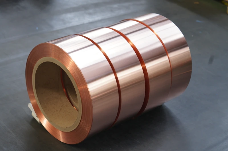
I. Functional Positioning of Copper Foil in Temperature Control Components
Copper foil serves four primary functions within temperature control components:
1. Electrical Connection Function In bimetallic strip thermostat switches and thermal protectors, copper foil acts as contact lead terminals and conductive strips, carrying start/stop signal currents. Its electrical conductivity directly determines contact system reliability.
2. Thermal Conduction Function High-purity oxygen-free copper (purity ≥ 99.95%) exhibits a thermal conductivity of up to 398 W/(m·K). In temperature-sensing assemblies, it serves as a thermal conduction medium, rapidly transmitting temperature changes from the thermally sensitive zone to control ICs or bimetallic strips—directly influencing thermal response time and control accuracy.
3. Flexible Circuit Substrate Function In household appliance thermostats, air-conditioning control boards, and battery management systems (BMS) for new-energy vehicles, flexible copper clad laminate (FCCL) serves as the critical substrate for temperature-sensing signal feedback.
4. Welding and Packaging Foundation Function Welding reliability between copper foil and components such as PTC thermistors, NTC sensors, and relay contacts forms the foundation for long-term stable operation of temperature control components.
II. Key Performance Indicators of Copper Foil for Temperature Control Components
Recommended grades: C1100 (ETP copper) or C1220 (DHP oxygen-free copper). Copper content shall be ≥ 99.95% (complying with ASTM B152), with oxygen content in C1220 ≤ 5 ppm to prevent hydrogen embrittlement. Electrical conductivity shall be ≥ 100% IACS (annealed condition at 20°C); temperature coefficient of resistance: 0.00393/°C.
Temperature control components operate under repeated thermal cycling over extended periods. Impurity elements in the copper matrix (e.g., oxygen, phosphorus, iron, sulfur) may cause:
- Resistance drift leading to reduced temperature measurement accuracy;
- Increased contact resistance after prolonged operation;
- Oxidation-induced failure under extreme operating conditions.
Typical thickness range for copper foil in temperature control components: 0.01–0.30 mm. Thickness specifications per application are as follows: | Application | Thickness Range | Tolerance | |————-|——————|———–| | Flexible temperature control circuits (FPC) | 0.01–0.05 mm | ±5% | | Thermostat switch contact leads | 0.05–0.15 mm | ±3% | | Thermal protector conductive strips | 0.10–0.20 mm | ±3% | | High-power thermostat busbars | 0.20–0.30 mm | ±2% | | Battery thermal management heater films | 0.035–0.070 mm | ±4% |
Thickness tolerance critically affects assembly consistency and thermal response time—and is a key control parameter for stamping yield. Width tolerance is typically maintained within ±0.05 mm, while coil length is customized per customer requirement.
Surface requirements vary across applications:
- Bare copper foil (RA/ED surface)** offers optimal conductivity and is suitable for subsequent welding or electroplating;
- Tin-plated copper foil (Sn: 1–3 μm) provides oxidation resistance and excellent solderability, with solderability retention period of 6 months**—the preferred choice for household appliance thermostats;
- Nickel-plated copper foil (Ni: 2–5 μm) withstands continuous temperatures >200°C**, suitable for industrial high-temperature and automotive electronics applications;
- Silver-plated copper foil (Ag: 0.5–2 μm)** delivers high conductivity and low contact resistance—ideal for high-end temperature sensors and signal circuits;
- OSP (organic solderability preservative, 0.2–0.5 μm)** offers environmental compliance and cost efficiency—commonly used in FPC-based flexible temperature control circuits.
Rolled copper foil (RA) exhibits superior flexibility and bend resistance compared to electrodeposited copper foil (ED), making it especially suitable for temperature probe structures requiring repeated bending.
Operating temperature ranges for temperature control components span −40°C to 250°C, including demanding applications such as industrial boilers and air compressors. Copper foil high-temperature resistance shall be evaluated across three dimensions:
- Short-term thermal resistance: Ability to withstand instantaneous high temperatures of 280–350°C** during soldering processes;
- Long-term thermal stability**: Resistance change rate ≤ 5% after prolonged exposure at rated operating temperature;
- Thermal fatigue resistance: No cracking or delamination after 10⁴–10⁶ thermal cycles**.
Testing methods may refer to IEC 61215, UL 1059, and other applicable standards.
Mechanical properties of copper foil are fundamental to achieving high yield in automated stamping and assembly processes:
| Temper | Tensile Strength | Elongation | Hardness (HV) | Bend Test (90°) | |——–|—————-|————|—————-|——————-| | Annealed (O) | ≥ 200 MPa | ≥ 30% | ≤ 50 | No cracking | | Half-hard (1/2H) | 220–280 MPa | 10–20% | 60–90 | Acceptable micro-cracking | | Hard (H) | ≥ 290 MPa | ≤ 5% | ≥ 95 | Micro-cracking permitted |
Thermostat switch contact leads and thermal protector conductive strips commonly employ annealed (O60/O80) copper foil, optimized for stamping formability and thermal fatigue resistance.
III. Copper Foil Selection for Typical Application Scenarios of Temperature Control Components
Operating Conditions: Repeated current interruption surges, long-term high-temperature environment, and mechanical stress from spring mechanisms. Recommended Specifications: Material C1100 annealed (O60) oxygen-free copper, thickness 0.10–0.20 mm, surface tin-plating 2–3 μm, width tolerance ±0.05 mm.
Operating Conditions: Extremely confined internal space, dense signal circuits, and requirement for long-term dimensional stability. Recommended Specifications: Material C1100 rolled copper foil (RA), thickness 0.020–0.050 mm, single- or double-sided reinforcement with PI film (polyimide, 12.5–25 μm), foldability ≥ 1,000,000 cycles (MIT method, bending radius 1.0 mm).
Operating Conditions: Operating temperature 130–180°C, vibration-prone environment, and soldered connection to PTC elements. Recommended Specifications: Material C1220 oxygen-free copper, thickness 0.15–0.30 mm, surface nickel-plating 3–5 μm, long-term operating temperature ≥ 180°C.
Operating Conditions: Operating temperature −40°C to 85°C (up to 120°C during fast charging), requirement for high purity and low electrical resistance, and resistance to electrolyte corrosion. Recommended Specifications: Material C1100 electrodeposited copper foil (ED), thickness 0.035–0.070 mm, double-sided roughening (Ra 0.5–1.5 μm) + nickel-plating or OSP (organic solderability preservative), laminated with PI film to achieve electrolyte corrosion resistance; compliant with automotive electronic reliability standards including GB/T 28046 and ISO 16750.
Operating Conditions: Operating temperature 60–90°C, sensitivity to long-term stability and cost. Recommended Specifications: Material C1100 copper foil, thickness 0.10–0.20 mm, surface tin-plating 1–2 μm, copper content ≥ 99.9%.
IV. Key Manufacturing Process Considerations for Copper Foil Used in Temperature Control Components
Copper foil parts in temperature control components are typically complex-shaped. High-speed stamping (200–800 strokes per minute, spm) is the dominant forming process. Critical control parameters include:
- Protective atmosphere annealing (nitrogen/ammonia) prior to stamping; optimal elongation of annealed copper foil ≥ 30%;
- Die clearance per side = 8%–10% of copper foil thickness;
- Burr height ≤ 0.01 mm to prevent short-circuiting during assembly;
- Stamping fillet radius R ≥ 0.2 mm to avoid stress concentration.
Welding processes commonly used for temperature control components impose specific requirements on copper foil:
- Wave soldering (250–280°C):** Requires surface tin-plating or OSP for thermal shock resistance;
- Reflow soldering (240–260°C):** Requires CTE matching between copper foil and substrate;
- Laser welding (localized 800–1200°C):** Requires clean, oxide-free surface;
- Soldering iron (340–400°C):** Prefers annealed (O temper) copper foil to prevent stress-induced cracking;
- Resistance welding (instantaneous high temperature):** Requires low electrical resistance and high electrical conductivity.
Insulation treatment is frequently applied to the outer surface of copper foil in temperature control components:
- PI film lamination (polyimide):** Withstands temperatures ≥ 200°C; suitable for flexible printed circuits (FPC) and high-temperature applications;
- Epoxy resin coating:** UL94 V-0 flame-retardant rating; cost-effective and widely adopted in household appliances;
- Polyimide tape wrapping:** Offers flexibility and adaptability for irregular geometries and small-batch R&D.
V. Typical Failure Modes and Mechanism Analysis
Failure Phenomenon: Blackening of copper foil contact surfaces and increased contact resistance after 6–18 months of thermostat operation. Failure Mechanism: Combined effect of ambient temperature and Joule heating induces continuous growth of copper oxide films (Cu₂O/CuO) on the surface. Improvement Measures: Use nickel-plated (≥ 3 μm) or tin-plated (≥ 2 μm) copper foil; incorporate anti-oxidation pre-assembly treatments.
Failure Phenomenon: Fracture at copper foil contact leads after 10⁴–10⁶ thermal cycles in thermostat switches. Failure Mechanism: Hard-temper (non-annealed) copper foil exhibits insufficient elongation (≤ 5%), leading to fatigue crack initiation and propagation under repeated thermal stress. Improvement Measures: Specify annealed (O60/O80) copper foil with elongation ≥ 30%; optimize stamping fillet radius R ≥ 0.2 mm.
Failure Phenomenon: Functional failure observed 3–12 months after shipment, despite passing factory QC validation. Failure Mechanism: Mismatch in coefficient of thermal expansion (CTE ≈ 17 ppm/°C) between copper foil and PTC/NTC elements or PCB substrates generates shear stress during thermal cycling, resulting in solder joint fracture. Improvement Measures: Use Sn-Ag-Cu (SAC) lead-free solder; optimize pad geometry to incorporate stress relief structures; apply nickel-plating on copper foil as a diffusion barrier layer.
Failure Phenomenon: Green rust (basic copper carbonate) formation and intermittent contact failure on copper foil in high-humidity environments. Failure Mechanism: Under humid conditions and micro-current flow, copper reacts with atmospheric H₂S, SO₂, and moisture to form corrosion products such as Cu₂(OH)₂CO₃ and Cu₄SO₄(OH)₆. Improvement Measures: Select tin-plated, nickel-plated, or silver-plated copper foil; elevate enclosure IP rating to IP54 or higher; implement moisture-proof packaging.
VI. Technical Evaluation Criteria for Copper Foil Suppliers
When selecting copper foil suppliers, manufacturers of temperature control components are advised to conduct a systematic evaluation across the following dimensions:
- Material Traceability System** — Does the supplier provide complete Mill Test Certificates (MTCs)? Can material traceability be extended to copper anode origin and melting batch?
- Dimensional Precision Control Capability** — Actual control levels for thickness tolerance, width tolerance, and coil length tolerance, along with associated Cpk values;
- Surface Consistency** — Plating thickness uniformity (CV ≤ 10%), surface roughness (Ra value), and OSP (organic solderability preservative) film thickness uniformity;
- International Certification Completeness** — ISO 9001, ISO 14001, and ISO 45001 system certifications; UL, REACH, and RoHS product certifications;
- R&D and Customization Capability** — Does the supplier support small-batch customization (e.g., thickness starting from 0.01 mm, non-standard widths, specialty platings)? What is the R&D response cycle?
- Supply Chain Stability** — Geographic distribution of production bases, minimum order quantity (MOQ), lead time, and inventory safeguarding strategy.
VII. Technical Specifications Overview (LP Industrial)
Zhengzhou LP Industry Co., Ltd. specializes in R&D and manufacturing of magnet wire and metal foil materials. Its products are exported to over 50 countries and regions, backed by 30 years of industry experience.
For temperature control components, LP Industrial offers copper foils with the following technical specifications:
- Material grades: C1100 (ETP copper), C1220 (DHP oxygen-free copper);
- Copper content: ≥ 99.95%;
- Electrical conductivity: ≥ 100% IACS (annealed condition at 20 °C);
- Thickness range: 0.010–0.300 mm;
- Thickness tolerance: ±2%, ±3%, or ±5% (as specified by customer);
- Width range: 5–600 mm;
- Surface treatments: bare copper, tin-plated copper foil, nickel-plated copper foil, silver-plated copper foil, OSP;
- Mechanical tempers: annealed (O temper), half-hard (1/2H), hard (H);
- Compliance with international standards: ASTM B152, IEC, GB, JIS, NEMA;
- System certifications: ISO 9001, ISO 14001, ISO 45001 (SGS-audited);
- Product certifications: UL certification, REACH compliance, RoHS compliance.
LP Industrial supports small-batch customization and joint R&D for new product development, with an R&D response cycle of 7–15 days.
Contact Information:
- Email: office@cnlpzz.com
- WhatsApp: +86-19337889070
VIII. Conclusion
The long-term reliability of temperature control components is jointly determined by design, material selection, and manufacturing process. As a critical base material, copper foil must achieve synergistic optimization across chemical composition, dimensional accuracy, surface condition, high temperature resistance, and mechanical performance—forming the technical foundation for quality assurance of temperature control components.
During material selection, a systematic evaluation shall be conducted based on the operational conditions of the target application scenarios (e.g., temperature range, current load, mechanical stress, environmental media), as well as compatibility requirements with stamping, welding, and packaging processes.
Leveraging its 30-year expertise in magnet wire and metal foil manufacturing, LP Industrial provides end-to-end technical support—from material selection and sample testing to mass production—for temperature control component manufacturers. Technical consultation and sample request are welcome.