
Copper Foil for Servo System Shielding: Technical Principles, Material Properties, and Industry Applications
Introduction
With the continuous improvement of industrial automation, servo systems are increasingly widely used in precision manufacturing, high-end equipment, and other fields. Electromagnetic interference (EMI) is a key factor affecting the stable operation of servo systems, and its protection measures have attracted much attention from the industry. Copper foil, as a highly efficient electromagnetic shielding material, plays an important role in the field of EMI protection for servo systems due to its excellent conductivity.
This article will systematically explain the application of copper foil in servo system shielding from the aspects of technical principles, material properties, application forms, and selection points.
I. EMI Shielding Technology Principles
1.1 Formation Mechanism of Electromagnetic Interference
Electromagnetic interference (EMI) refers to the phenomenon that electromagnetic energy affects the normal operation of electronic equipment through conduction or radiation. According to the transmission path, EMI can be divided into two categories: conducted interference and radiated interference.
Conducted interference mainly propagates through conductors such as power lines and signal lines; radiated interference propagates in the form of spatial electromagnetic waves. For servo systems, the electromagnetic radiation generated by the IGBT power module inside the driver during high-frequency switching is the main cause of system instability.
1.2 Metal Shielding Mechanism
The shielding effectiveness of metal materials against electromagnetic waves mainly depends on two mechanisms:
Reflection Loss (R): When electromagnetic waves are incident on a metal surface, reflection occurs due to the difference between the wave impedance and the characteristic impedance of the metal. The higher the conductivity of the metal material, the greater the reflection loss. The bulk conductivity of copper is 5.96 × 10⁷ S/m, approximately 1.6 times that of aluminum, therefore copper foil has superior reflection shielding characteristics.
Absorption Loss (A): When electromagnetic waves penetrate the metal surface and propagate inside the metal, they induce current and convert it into heat energy. Absorption loss is closely related to the metal thickness and skin depth. The formula for calculating the skin depth δ is:
δ = √(ρ / (π × f × μ))
Where ρ is the resistivity of the material, f is the frequency of the electromagnetic wave, and μ is the permeability of the material.
At 1MHz, the skin depth of copper is approximately 0.066mm; at 100MHz, it is approximately 0.007mm. This means that a thin layer of copper foil can provide effective shielding against high-frequency interference.
1.3 EMI Sensitivity Characteristics of Servo Systems
The EMI sensitivity of servo systems stems from their high-precision control characteristics. The PWM signal frequency output by the driver is typically 10-20kHz, while the amplitude of the encoder feedback signal is only in the milliampere range. When external interference signals are superimposed on the useful signal, it will lead to rotor position detection errors, increased torque ripple, and in severe cases, trigger the system’s overcurrent protection.
Common interference frequency bands for servo systems are concentrated in the 100kHz to 100MHz range, which precisely covers the operating frequencies of most switching power supplies, inverters, and wireless communication devices. Copper foil materials can provide 60-80dB of attenuation in this frequency band, meeting the shielding requirements of precision servo systems.
II. Material Comparison Analysis of Copper Foil and Aluminum Foil
2.1 Comparison of Conductivity
| Performance Indicators | Copper Foil | Aluminum Foil |
|---|---|---|
| Conductivity | 5.96×10⁷ S/m | 3.77×10⁷ S/m |
| Relative Conductivity (based on copper) | 100% | 63% |
| Thermal Conductivity | 401 W/(m·K) | 237 W/(m·K) |
| Melting Point | 1083°C | 660°C |
From the perspective of conductivity, copper foil has significantly better conductivity than aluminum foil. Under the same thickness conditions, the shielding effectiveness of copper foil is about 20-30% higher than that of aluminum foil.
2.2 Comparison of Long-Term Stability
Aluminum foil faces oxidation problems in practical applications. The aluminum oxide layer (Al₂O₃) that forms on the surface of aluminum has high resistivity, leading to increased contact resistance and decreased shielding effectiveness. Especially in humid or corrosive industrial environments, the oxidation rate of aluminum foil accelerates significantly.
Copper also forms an oxide layer, but both copper oxide (CuO) and cuprous oxide (Cu₂O) maintain a certain level of conductivity, having a smaller impact on overall shielding performance. From a long-term stability perspective, copper foil is more suitable for long-term applications in harsh industrial environments.
2.3 Comparison of Processing Performance
Copper foil has higher mechanical strength than aluminum foil, requiring a larger bending radius when bending. However, copper foil has excellent weldability, facilitating reliable electrical connections through soldering, resistance welding, and other methods. While aluminum foil is highly flexible, it is more difficult to weld and requires specialized aluminum soldering processes.
Considering the actual needs of servo systems, for general industrial applications, a copper foil thickness of 0.05-0.1mm is recommended; for high-precision applications such as semiconductor equipment and medical robots, a copper foil thickness of 0.15mm or more is recommended to ensure sufficient shielding margin.
III. Typical Applications of Copper Foil in Servo Systems
3.1 Driver Housing Shielding
As the core control unit of the system, the high-frequency switching action of the internal IGBT module of the servo driver is the main source of EMI radiation. Typical IGBT switching frequencies are 10-20kHz, generating harmonic components up to several MHz.
Most current mainstream servo drivers use aluminum alloy housings. While the material itself has certain shielding properties, the surface oxide layer reduces conductivity after anodizing, leading to a decrease in shielding effectiveness.
Recommended Solution: Attach 0.05-0.1mm thick copper foil to the inside of the driver housing. The edges of the copper foil are connected to the housing ground with conductive tape for low impedance. This solution can effectively improve shielding effectiveness by 20-30dB.
3.2 Motor Cable Shielding
The servo motor cable simultaneously performs the dual functions of power transmission and encoder signal feedback. The differential signal amplitude transmitted by the encoder feedback line is only a few hundred millivolts, making it extremely sensitive to interference.
While shielded cables commonly used in industrial settings have built-in braided shielding layers, these layers are prone to breakage and failure due to repeated bending in high-dynamic scenarios such as cable chain applications.
Supplementary Shielding Solution: Wrap copper foil around the outer layer of the cable, ensuring the overlap length covers the entire 360-degree circumference. Use a crimp-type OT terminal to reliably connect the grounding terminal to the equipment grounding busbar.
3.3 Overall Cabinet Shielding
When multiple servo drives are installed in a single cabinet, the EMI coupling problem between drives is particularly prominent. Furthermore, when high-power inverters, switching power supplies, and other equipment coexist with the servo system in the same power distribution system, conducted interference formed through common impedance coupling cannot be ignored.
Key Points of Cabinet Shielding Solution:
- Full copper foil lining the inner wall of the cabinet, with overlapping welding at the joints
- All gaps are sealed using a combination of conductive foam and copper foil
- EMI filters are installed at cable entry points
- Door frame contact surfaces are sealed with comb-shaped springs or conductive rubber
Crucial Detail: The gap between the cabinet door and the enclosure must be strictly controlled. Studies have shown that a 1mm gap can lead to approximately 30dB of leakage at 1GHz.
3.4 PCB-Level Shielding
In high-end servo driver PCB design, board-level shielding is typically required for critical signal areas such as power module drive circuits and encoder interface circuits.
Board-level shielding is generally made of 0.035-0.05mm thick copper foil processed using a chemical etching process. The copper frame is electrically connected to the PCB ground plane via reflow soldering, creating a complete shielding cavity at the PCB level.
IV. Copper Foil Selection Technical Guide
4.1 Thickness Specifications Selection
| Thickness Specifications | Applicable Scenarios | Shielding Effectiveness (Typical Value) |
|---|---|---|
| 0.035mm | PCB board-level shielding, space-constrained applications | 40-50dB |
| 0.05mm | Driver housing shielding, general industrial applications | 60-70dB |
| 0.1mm | Cabinet shielding, cable shielding | 70-80dB |
| 0.2mm | High protection level requirements, harsh outdoor environments | Above 80dB |
4.2 Material Type Selection
Electrolytic Copper Foil: Produced through electrolytic deposition process, copper purity can reach over 99.8%. Lower production cost, suitable for general industrial applications.
Rolled Copper Foil: Produced through mechanical rolling, it has excellent ductility and is suitable for applications requiring complex forming. Copper purity can reach over 99.9%.
4.3 Surface Treatment Selection
| Surface Treatment | Characteristics | Applicable Scenarios |
|---|---|---|
| Bare Copper | Excellent weldability, prone to oxidation | General industrial applications |
| Tin Plating | Good oxidation resistance, good weldability | Requires long-term storage or outdoor applications |
| Nickel Plating | Strong corrosion resistance, high temperature resistance | Harsh industrial environments |
4.4 Adhesive Type Selection
The selection of the adhesive layer needs to consider the actual operating temperature. Oil-based adhesives have a temperature resistance range of up to 150°C, suitable for shielding applications near power equipment; water-based adhesives are more environmentally friendly, but their temperature resistance is generally below 80°C.
V. Installation and Construction Specifications
5.1 Continuity Requirements for Overlapping
The realization of shielding effectiveness is based on the integrity of the shielding body. Any discontinuity in the overlap will become a path for electromagnetic wave leakage.
Technical Requirements:
- All overlaps must achieve reliable electrical connection, and the contact resistance should be less than 1mΩ.
- The overlap width should not be less than 20mm.
- The overlap spacing should not exceed 1/20 of the shielding wavelength.
5.2 Grounding Design Specifications
Grounding of the shielding layer is a key prerequisite for ensuring shielding effectiveness. The grounding design should follow these principles:
- Use wide and short grounding braided tape, with an aspect ratio not greater than 1:20.
- The length of the grounding wire should not exceed 1/20 of the distance from the shielding layer to the ground.
- The grounding arrangement should adopt a star grounding method to avoid common impedance coupling.
5.3 Thermal Management Considerations
The sealed structure of the metal shielding layer will affect the heat dissipation of the equipment. When implementing shielding near heat sources such as drivers, the arrangement of heat dissipation channels should be fully considered during the design phase. If necessary, a forced air cooling solution with heat sinks can be used.
VI. Industry Application Cases
Case 1: Photovoltaic Tracking Bracket System
A photovoltaic tracking bracket manufacturer’s servo system is used in outdoor high and low temperature difference environments. The original aluminum foil shielding solution resulted in aluminum foil powdering after two years, causing severe EMI interference.
Improved Solution: Replace the original aluminum foil with 0.1mm tin-plated copper foil.
Application Results: After five years of continuous operation, system stability has significantly improved.
Case Two: Semiconductor Wafer Handling Equipment
A semiconductor equipment manufacturer’s wafer manipulator requires a positioning accuracy better than 0.01mm. During equipment commissioning, occasional jitter was observed during high-speed movement.
Problem Analysis: The driver’s IGBT high-frequency switch interfered with the encoder feedback signal.
Improved Solution:
- Attach 0.05mm copper foil to the inside of the driver housing
- Add copper foil tubing to the outer layer of the encoder cable.
Application Results: The jitter was eliminated, and the positioning accuracy remained stable and met the requirements.
Case Three: New Energy Vehicle Welding Production Line
A car welding workshop has 24 servo motors operating collaboratively with extremely high cycle time requirements. During commissioning, multiple servos simultaneously alarmed at specific times.
Problem Analysis: Harmonics generated by the reactive power compensation cabinet in the substation are transmitted to the servo system through the power distribution system.
Improvement Solution: Implement copper foil shielding for the entire cabinet, and independently ground each driver.
Application Effect: Harmonic interference is eliminated, and system synchronization accuracy is stable.
VII. Product Technical Specifications
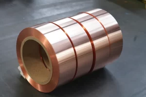
As a manufacturer with 30 years of experience in the electrical industry, our company provides the following copper foil products for servo system shielding:
| Technical Parameters | Specifications |
|---|---|
| Thickness | 0.035 / 0.05 / 0.1 / 0.2 mm |
| Width Range | 10-500 mm (customizable) |
| Copper Material | Pure Copper (Cu≥99.9%) |
| Surface Treatment | Bare Copper / Tin Plated / Nickel Plated |
| Adhesive Type | Oil-based Adhesive (150°C resistance) / Water-based Adhesive (80°C resistance) |
| Standards | IEC 60250, ASTM B152 |
| Product Certifications | ISO9001, UL, REACH, RoHS |
Products are mainly exported to more than 50 countries and regions worldwide, supporting factory direct and technical customization services.
VIII. Common Technical Questions
Q1: Why must copper foil shielding be grounded?
After the shielding layer is grounded, interference current can be discharged to the ground through a low-impedance path. If the shielding layer is suspended, the induced voltage will form a distributed capacitance coupling between the cable shielding layer and the internal conductor, which is not conducive to interference suppression. Grounding is a necessary condition to ensure shielding effectiveness.
Q2: What is the service life of copper foil?
Under normal industrial conditions, the service life of copper foil can reach more than 10 years. One of our outdoor photovoltaic tracking bracket customers reported that there was no significant performance degradation after 15 years of continuous use. However, in environments with high concentrations of acid and alkali corrosive gases, it is recommended to add a protective coating.
Q3: Can copper foil be cut and processed by oneself?
Copper foil can be cut using standard sheet metal tools. However, for shielding covers with complex shapes, it is recommended to use professional etching or stamping processes to ensure edge flatness and dimensional accuracy.
Q4: What is the difference in shielding effectiveness between copper foil and copper mesh?
Under the same thickness conditions, copper foil has a higher surface conductivity than copper mesh, thus providing superior shielding effectiveness. Copper mesh has the advantages of good ventilation and heat dissipation performance and light weight, making it suitable for shielding cover designs that require heat dissipation considerations.
Conclusion
Electromagnetic compatibility design of servo systems is a key aspect of ensuring stable equipment operation. Copper foil, with its excellent conductivity, reliable long-term stability, and good processing performance, demonstrates significant technical advantages in the field of EMI shielding for servo systems.
Our company has 30 years of experience in the wire and shielding materials industry, and can provide customers with comprehensive services including technical selection consultation, application solution design, and on-site technical guidance. Please feel free to contact us if you have any related needs.
Contact Information
Email: office@cnlpzz.com
WhatsApp: 0086-19337889070
This article was compiled by Zhengzhou LP Industry Co., Ltd., specializing in the research and manufacturing of magnetic wire and shielding materials for thirty years.