


Introduction
PCB (Printed Circuit Board) is the core carrier of electronic products, responsible for electrical connection of components, mechanical support, and heat dissipation. As electronic products develop toward high power, high density, and high reliability, the current carrying capacity, heat dissipation performance, and mechanical strength of traditional PCB copper foil face severe challenges. PCB circuit reinforcement technology emerged, significantly improving the electrical, thermal, and mechanical performance of PCBs by adding additional copper foil layers to existing circuits or key areas.
Main application scenarios for PCB circuit reinforcement include: high-current circuit reinforcement (power boards, motor driver boards), high heat dissipation area reinforcement (LED boards, power device cooling), mechanical stress concentration area reinforcement (BGA pads, connector pads, gold fingers/edge connectors), flexible circuit reinforcement areas (flex board bending areas, rigid-flex boards), and electromagnetic shielding reinforcement.
As the key material for PCB circuit reinforcement, copper foil’s thickness, purity, surface treatment, and composite process directly affect the reinforcement effect. This article systematically explains key parameters, selection criteria, and industrial applications for copper foil used in PCB circuit reinforcement, serving as a professional reference for PCB manufacturers and procurement personnel.
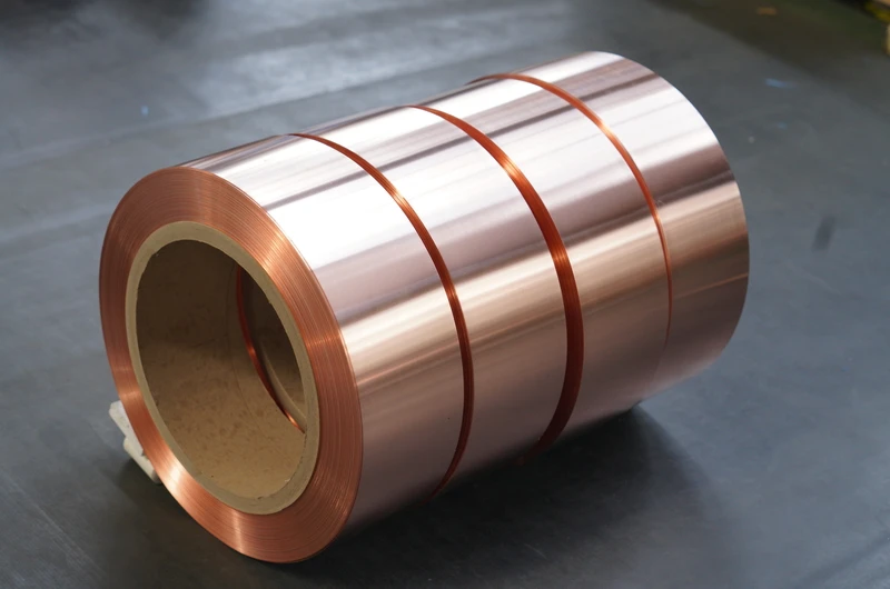
1. PCB Circuit Reinforcement Structure and Copper Foil Role
1.1 Basic Principles of PCB Circuit Reinforcement
PCB circuit reinforcement achieves the following purposes by adding additional copper foil layers or other reinforcing materials to existing circuit structures:
Increasing current carrying capacity: Thicker copper layers can significantly improve the current carrying capacity of circuits. In PCB design, 1 oz copper (35μm) circuit’s current carrying capacity is approximately 2A (temperature rise 10°C); if 1 oz reinforcement copper is added (total thickness 2 oz/70μm), current carrying capacity can be increased by approximately double.
Improving heat dissipation: Copper’s high thermal conductivity (approximately 401W/m·K) makes it an excellent heat dissipation material. Adding copper foil reinforcement below power devices can significantly reduce junction temperature, improving device lifespan and reliability.
Enhancing mechanical strength: Adding copper foil reinforcement at mechanical stress concentration points such as pads and connector mounting areas can reduce pad peeling, circuit fracture, and other mechanical failures.
Improving electromagnetic compatibility: Adding copper foil reinforcement in signal layers or ground layers can improve electromagnetic shielding effect and signal integrity.
1.2 Typical Applications of Copper Foil in PCB Reinforcement
Copper foil applications in PCB circuit reinforcement mainly include:
High-current circuit reinforcement: Add copper foil to high-current circuits (>5A) of power boards and motor driver boards, improving current carrying capacity and heat dissipation.
BGA pad reinforcement: Add copper foil below BGA (Ball Grid Array) pads, enhancing pad mechanical strength and reducing pad cracking risk.
Connector pad reinforcement: Add copper foil below connector pads (especially gold fingers/edge connectors), improving mating life and tensile strength.
Flexible board bending area reinforcement: Add copper foil in bending areas of flexible PCBs, but special structural design is needed to avoid affecting bending performance.
Power device heat dissipation reinforcement: Add copper foil below MOSFET, IGBT, LED, and other power devices to assist heat dissipation.
Gold finger/edge connector reinforcement: Add copper foil in PCB edge connector areas, ensuring mating reliability.
Heat dissipation via copper capping: Cover copper foil on heat dissipation vias, enhancing via heat dissipation capability.
1.3 Main Failure Modes of PCB Reinforcement
Understanding reinforcement failure modes helps understand the importance of copper foil selection:
Reinforcement layer delamination: Insufficient bonding between reinforcement copper foil and original PCB substrate leads to delamination.
Reinforcement copper foil fracture: Reinforcement copper foil fractures under repeated thermal or mechanical stress.
Pad cracking: Reinforcement copper foil below pads bonds poorly with original circuits, leading to pad cracking.
Heat dissipation failure: Thermal resistance exists between reinforcement copper foil and original copper layer, causing poor heat dissipation effect.
Warping deformation: Asymmetric distribution of reinforcement copper foil causes PCB warping.
As PCB reinforcement material, copper foil needs to balance conductivity, bonding force, thermal conductivity, mechanical strength, and processability.
2. Key Specifications and Technical Requirements
2.1 Copper Foil Purity
Copper foil purity directly affects the conductivity, thermal conductivity, and weldability of PCB reinforcement.
Standard electrolytic copper (99.9%): The most commonly used PCB reinforcement copper foil, conductivity approximately 98% IACS, suitable for most PCB reinforcement applications.
High-purity electrolytic copper (99.95%): Conductivity above 100% IACS, suitable for high-frequency, high heat dissipation PCB reinforcement applications.
Oxygen-free copper (99.99%): Extremely low impurity content, suitable for high-end PCB and military, aerospace fields.
Rolled copper (99.99%): Prepared through rolling process, dense crystalline structure, better flexibility and bending resistance, the preferred material for flexible PCB reinforcement.
Selection advice: Standard electrolytic copper foil is usually used for rigid PCB reinforcement; rolled copper foil must be used for flexible PCB reinforcement; high-purity copper or oxygen-free copper is recommended for high heat dissipation/high frequency applications.
2.2 Thickness Selection
Copper foil thickness is the key parameter determining PCB reinforcement effect, needing to be selected according to reinforcement purpose.
Thin reinforcement copper foil (1/3 oz – 1/2 oz, 12μm–18μm): Used for slight reinforcement, signal circuit fine-tuning, flexible board local reinforcement. Increases a small amount of current carrying capacity, with little weight increase.
Standard reinforcement copper foil (1 oz, 35μm): Used for general BGA pad reinforcement, connector pad reinforcement, conventional heat dissipation reinforcement. The most commonly used thickness for PCB reinforcement.
Thickened reinforcement copper foil (2 oz, 70μm): Used for high-current circuit reinforcement, high-power device heat dissipation reinforcement. Current carrying capacity increased by approximately 70%–80% compared to 1 oz copper.
Ultra-thick reinforcement copper foil (3 oz – 6 oz, 105μm–210μm): Used for ultra-high current (>20A) circuits, high-power module (IGBT, SiC) heat dissipation. Common in power boards, electronic control boards.
Extreme thick copper foil (6 oz – 12 oz, 210μm–420μm): Used for industrial power supplies, welding machines, battery management, and other ultra-high current applications.
Selection advice: General BGA and connector reinforcement use 1 oz copper; high-current circuit reinforcement uses 2 oz–3 oz copper; power module heat dissipation reinforcement uses 3 oz–6 oz copper. Note that excessively thick copper foil will cause PCB warping and increased processing difficulty.
2.3 Width and Dimensions
Copper foil width is determined according to the specific size of PCB reinforcement area.
Standard width range: Usually between 5mm and 500mm, customizable according to reinforcement area dimensions.
Width precision: Copper foil width tolerance should be strictly controlled (usually within ±0.1mm) to ensure precise fit.
Slitting quality: Edges should be neat and burr-free, avoiding debris or damage to PCB during lamination process.
2.4 Surface Treatment
Surface treatment of PCB reinforcement copper foil is crucial to bonding force and reliability.
Browning treatment (black oxidation): Form microscopic copper oxide/cuprous oxide layer on copper foil surface, significantly improving bonding force with prepreg (PP). Browning treatment is the most commonly used surface treatment for PCB reinforcement copper foil.
Chemical roughening: Form micro-rough surface on copper foil surface through chemical methods, improving mechanical bonding force with resin.
Zinc plating/nickel plating treatment: Improve corrosion resistance and weldability in specific application scenarios.
Anti-oxidation treatment (anti-oxidation coating): Apply organic protective layer on copper foil surface, preventing oxidation during storage and processing.
Selection advice: Standard PCB reinforcement copper foil should use browning treatment to ensure reliable bonding with PP.
2.5 Mechanical Properties
PCB reinforcement has specific requirements for copper foil mechanical properties:
Tensile strength: Rigid PCB reinforcement usually uses hard state copper foil (tensile strength 300–380MPa), ensuring reinforcement layer strength.
Elongation: Hard state copper foil elongation 3%–8%, half-hard state copper foil elongation 15%–25%.
Flexibility: Flexible PCB reinforcement must use rolled copper foil (elongation ≥20%), ensuring bending performance.
Peel strength: Peel strength between reinforcement copper foil and substrate should be ≥1.0 N/mm (90° peel test).
2.6 Electrical and Thermal Conductivity Performance
Electrical and thermal conductivity performance of PCB reinforcement copper foil:
Conductivity: Standard electrolytic copper approximately 98% IACS, oxygen-free copper ≥101% IACS, rolled copper approximately 100% IACS.
Thermal conductivity: Pure copper’s thermal conductivity approximately 401W/m·K, nearly 2 times that of aluminum alloy, nearly 5 times that of steel.
Resistivity: 1.7×10⁻⁸Ω·m (standard electrolytic copper), the purer the copper foil, the lower the resistivity.
Current carrying capacity (reference value, temperature rise 10°C, 1mm wide circuit):
- 1/2 oz (18μm) copper: approximately 1.0A
- 1 oz (35μm) copper: approximately 2.0A
- 2 oz (70μm) copper: approximately 3.5A
- 3 oz (105μm) copper: approximately 5.0A
- 6 oz (210μm) copper: approximately 8.0A
3. PCB Reinforcement Process
3.1 Inner Layer Reinforcement Process
Inner layer reinforcement is adding additional copper foil layers to PCB inner layer core boards. Process flow:
- Prepare reinforcement copper foil (cut to appropriate size)
- Browning treatment (if needed)
- Laminate with prepreg (PP)
- High temperature high pressure lamination in press (temperature 170–200°C, pressure 300–400psi)
- Drilling, hole metallization, outer layer pattern making
3.2 Outer Layer Reinforcement Process
Outer layer reinforcement is adding additional copper foil layers to PCB outer layer. Process flow:
- Complete inner layer production
- Apply PP or resin on outer layer
- Attach reinforcement copper foil
- Lamination
- Outer layer etching to form circuits
3.3 Local Reinforcement Process
Local reinforcement is adding copper foil to specific areas of PCB:
Selective electroplating: Increase copper layer thickness in specific areas through electroplating method.
Copper foil attachment: Bond pre-cut copper foil to PCB local area through resin.
Embedded reinforcement: Embed copper foil into PCB structure, integrally formed with PCB.
3.4 Flexible Board Reinforcement Process
Flexible PCB reinforcement requires special processes:
Rigid-flex board: Use rolled copper foil in flexible areas, use reinforcement materials (such as PI, FR4) in rigid areas.
Local reinforcement: Use rolled copper foil reinforcement in key areas (such as pads, component mounting areas) of flexible boards.
Heat dissipation reinforcement: Use rolled copper foil reinforcement below power devices on flexible boards.
4. Insulation Class and Temperature Management
4.1 Effect of Temperature on PCB Reinforcement
The impact of temperature on PCB reinforcement copper foil:
Conductivity change: When temperature rises, copper foil resistance increases, affecting circuit current carrying capacity.
Thermal expansion: Differences in thermal expansion coefficient between copper foil and substrate (copper 17 ppm/°C, FR4 approximately 14 ppm/°C) may produce thermal stress at high temperatures.
Oxidation acceleration: High temperature accelerates copper foil surface oxidation, affecting weldability and bonding force.
Thermal fatigue: Under repeated thermal cycling, reinforcement copper foil may delaminate from substrate.
4.2 PCB Substrate Temperature Resistance Grades
Temperature resistance grades (TG point, glass transition temperature) of common PCB substrates:
| Substrate Type | TG Point | Applicable Field | Reinforcement Copper Foil Selection |
|---|---|---|---|
| Standard FR4 | 130–140°C | Consumer electronics | Standard electrolytic copper + browning |
| Medium TG FR4 | 150–160°C | Industrial control | Standard electrolytic copper + browning |
| High TG FR4 | 170–180°C | Automotive electronics | High-purity copper + browning |
| Modified epoxy | 180–200°C | High frequency high speed | High-purity copper + browning |
| PI polyimide | Above 250°C | Flexible boards, military | Rolled copper + browning |
| BT resin | 180–200°C | Packaging substrates | High-purity copper + browning |
4.3 Working Temperature Range
Working temperature range of PCB reinforcement copper foil:
- Consumer electronics: -20°C to +85°C
- Industrial control: -40°C to +85°C
- Automotive electronics: -40°C to +125°C
- Military/aerospace: -55°C to +150°C
- Special industrial: -55°C to above +200°C
5. Industrial Applications and Selection Recommendations
5.1 Consumer Electronics Field
Consumer electronics PCBs have specific reinforcement requirements.
Smartphone main boards: Use 1 oz copper reinforcement at key positions such as BGA pads, connector pads, and SIM card holders, improving mechanical reliability. Recommended: standard electrolytic copper (35μm) + browning treatment.
Tablet/laptop main boards: Use 1 oz–2 oz copper reinforcement at CPU/GPU pads, connector pads. Recommended: high-purity copper (35μm–70μm) + browning treatment.
LED lighting PCBs: Use 1 oz–2 oz copper reinforcement at LED pads and heat dissipation areas, improving heat dissipation performance. Recommended: standard electrolytic copper (35μm–70μm) + browning treatment.
Smart wearable devices: Use flexible PCB reinforcement, with rolled copper (35μm–50μm) + PI substrate at pad areas.
5.2 Automotive Electronics Field
Automotive PCBs have strict reinforcement requirements, especially for new energy vehicle power boards.
Automotive control boards (ECU): Use 1 oz–2 oz copper reinforcement at BGA, connector pads. Recommended: high TG FR4 + 1 oz–2 oz copper reinforcement + browning treatment.
New energy vehicle main control boards: Use 2 oz–6 oz copper reinforcement below IGBT, SiC power modules, providing high current carrying and heat dissipation. Recommended: high-purity copper (70μm–210μm) + ceramic substrate or high TG substrate.
Automotive BMS boards: Use 1 oz–3 oz copper reinforcement at current detection areas of battery management system. Recommended: high-purity copper (35μm–105μm) + browning treatment.
In-vehicle entertainment/navigation boards: Use standard 1 oz copper reinforcement.
5.3 Industrial Control and Power Supply Field
Industrial PCBs have high requirements for reinforcement current carrying and heat dissipation.
Industrial power boards: Use 3 oz–6 oz copper reinforcement in main circuit areas, carrying high current. Recommended: high-purity copper (105μm–210μm) + high TG substrate + browning treatment.
Industrial control boards: Use 1 oz–2 oz copper reinforcement. Recommended: standard electrolytic copper (35μm–70μm) + browning treatment.
Variable frequency drives/drivers: Use 3 oz–12 oz copper reinforcement below power modules. Recommended: high-purity thick copper foil (105μm–420μm) + ceramic substrate or metal substrate.
Welding machines/battery management: Use 6 oz–12 oz ultra-thick copper reinforcement. Recommended: thick copper foil (210μm–420μm) + high-performance substrate.
5.4 Communication Equipment Field
Communication PCBs have special requirements for high frequency and heat dissipation.
5G base station PCBs: Use 2 oz–3 oz copper reinforcement in RF power amplifier areas, enhancing heat dissipation. Recommended: high-purity copper (70μm–105μm) + low-loss substrate.
Optical module PCBs: Use 1 oz–2 oz copper reinforcement at optical device pads. Recommended: high-purity copper (35μm–70μm) + high-frequency substrate.
Server/data center boards: Use 2 oz–6 oz copper reinforcement below CPU/GPU. Recommended: high-purity copper (70μm–210μm) + high TG substrate.
5.5 Common Selection Problems and Solutions
Reinforcement layer delamination: Check copper foil surface browning treatment quality; confirm lamination temperature and pressure; consider changing browning process or increasing browning layer thickness.
Insufficient current carrying capacity: Check if copper foil thickness is sufficient; confirm copper foil conductivity; consider using thicker copper foil or adding more copper foil layers.
Poor heat dissipation effect: Check thermal resistance between copper foil and original copper layer; confirm if there are thermal via connections; consider increasing copper foil thickness or increasing the number of thermal vias.
Pad cracking: Check bonding force between reinforcement copper foil and substrate; confirm if pad design is reasonable; consider increasing reinforcement copper foil area or improving browning treatment.
PCB warping deformation: Check symmetric distribution of reinforcement copper foil; confirm lamination process; consider redesigning symmetry of reinforcement copper foil.
High-frequency signal loss: Check copper foil roughness (excessive roughness will increase high-frequency loss); consider using low-roughness RTF (Reverse Treated Foil) or HVLP (Hyper Very Low Profile) foil.
Insufficient lamination: Check lamination temperature, pressure, and time; confirm PP (prepreg) flow; consider using better-flowing PP or adjusting lamination parameters.
6. Supplier Selection and Quality Control
6.1 Quality Certifications
ISO9001 quality management system certification is the basic requirement. IATF16949 certification is necessary for automotive PCB applications. UL certification is necessary for export PCB products. RoHS, REACH environmental certifications are necessary for overseas markets. AS9100 certification is necessary for aerospace PCB applications.
6.2 Technical Capability Evaluation
Custom cutting capability: Whether reinforcement copper foil with specific dimensions and shapes can be cut according to customer drawings. Whether sample development cycle is reasonable (typically 5–10 working days).
Browning treatment capability: Whether mature browning treatment process is available, able to provide stable bonding force.
Thickness coverage range: Whether full range thickness copper foil from 1/3 oz to 12 oz can be provided, meeting different application needs.
Process quality control: Whether key control capabilities such as thickness testing, browning film testing, purity testing, and peel strength testing are available. Whether on-site supervision and third-party testing are supported.
6.3 Production Capacity and Delivery
Stable production capacity is the guarantee for long-term supply. It is recommended to select suppliers with monthly production capacity above 100 tons and complete browning treatment capability. Quick response capability and flexible delivery arrangements are also important considerations.
7. Product Specifications Summary
| Parameter | Specification Range |
|---|---|
| Copper Foil Type | Standard electrolytic copper / Rolled copper / High-purity copper / Oxygen-free copper |
| Purity | 99.9% – 99.99% |
| Thickness | 12μm – 420μm (1/3 oz – 12 oz) |
| Width | 5mm – 500mm |
| Surface Treatment | Browning / Chemical roughening / Zinc plating / Anti-oxidation coating |
| Tensile Strength | 220MPa – 400MPa |
| Elongation | 3% – 30% |
| Browning Film Color | Brown red / Black |
| Standards | IPC-4562 / IPC-4563 / GB / JIS / ASTM |
8. Technical Support and Contact
For detailed product specifications, samples, or technical selection support, please contact Zhengzhou LP Industry Co., Ltd. With years of expertise in electronic copper materials exports, our copper foil products are widely used in PCB circuit reinforcement, rigid-flex boards, power module heat dissipation, connector reinforcement, and other fields.
- Email: office@cnlpzz.com
- Phone/WhatsApp: 0086-19337889070
- Key Products: Copper foil, PCB reinforcement copper foil, Browning copper foil, Rolled copper foil, Thick copper foil
This document provides professional guidance for copper foil selection in PCB circuit reinforcement applications. For specific projects, please consult with technical professionals based on actual operating conditions.