
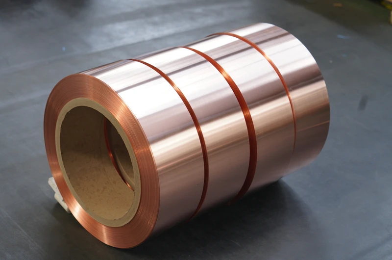
Copper foil for output reactors is a key conductive material in the manufacturing of output reactor windings in power electronic equipment. Output reactors are widely used in inverters, servo drives, inverters, UPS uninterruptible power supplies, photovoltaic inverters, wind power converters, and other equipment, playing an important role in filtering, current limiting, and protecting power devices.
I. Operating Characteristics of Output Reactors
Output reactors are installed in series on the output side of inverters or inverters and connected to the load. Their operating characteristics are as follows: The operating frequency is typically in the range of 0-400Hz, and some high-frequency applications can reach above 1kHz. Load changes cause temperature fluctuations, ranging from room temperature to 80-100°C. The electromagnetic force during operation is relatively large; during a short-circuit fault, the electromagnetic force can reach hundreds of times that during normal operation. The copper loss of high-power reactors can reach several kilowatts, requiring good heat dissipation design.
The core functions of output reactors include: suppressing harmonic currents, limiting short-circuit currents, improving motor operation, filtering, and decoupling.
II. Four Requirements for Copper Foil Materials
First, excellent conductivity. Copper content ≥99.90%, conductivity IACS ≥98%, reducing copper loss and temperature rise.
Second, good high-frequency performance. Skin depth calculation formula: δ=66.1/√f (mm). Thinner copper foil should be selected for high-frequency applications to avoid increased resistance due to the skin effect.
Third, stable mechanical properties. Able to withstand electromagnetic mechanical stress during operation, including vibration during normal operation and the huge impact force during short-circuit faults.
Fourth, reliable dimensional accuracy. The accuracy of thickness and width directly affects the electrical parameters of the reactor, and thus the stability of the entire system.
III. Detailed Explanation of Parameters
3.1 Copper Foil Substrate
- Material: Pure copper C11000, copper content ≥99.90%
- Conductivity: Annealed state IACS ≥98%
- Thickness Range: 0.05-2.0mm
- Width Range: 5-400mm
3.2 Mechanical Property Parameters
O State (Annealed State): Tensile strength 200-260MPa, elongation ≥35%, hardness 40-50HV
H04 State (Semi-hard State): Tensile strength 260-320MPa, elongation ≥20%, hardness 50-65HV
H06 State (Hard State): Tensile strength ≥320MPa, elongation ≥5%, hardness ≥65HV
3.3 High-Frequency Performance Parameters
| Operating Frequency | Skin Depth | Recommended Copper Foil Thickness |
|---|---|---|
| 50Hz | 9.4mm | 0.5-2.0mm |
| 100Hz | 6.6mm | 0.3-1.0mm |
| 200Hz | 4.7mm | 0.2-0.6mm |
| 400Hz | 3.3mm | 0.15-0.4mm |
| 1kHz | 2.1mm | 0.1-0.25mm |
| 2kHz | 1.5mm | 0.08-0.15mm |
| 5kHz | 0.94mm | 0.05-0.1mm |
IV. Selection Guide
4.1 Selection by Power Rating
| Power Rating | Recommended Thickness | Recommended Width | Recommended State |
|---|---|---|---|
| Low Power (<5kW) | 0.1-0.3mm | 10-50mm | O-state |
| Medium Power (5-50kW) | 0.2-0.5mm | 20-100mm | O-state or H04-state |
| High Power (50-200kW) | 0.3-1.0mm | 50-200mm | H04-state |
| Ultra-high Power (>200kW) | 0.5-2.0mm | 100-400mm | H04-state or H06-state |
4.2 Selection by Operating Frequency
Low-frequency (50-100Hz): Ordinary thickness copper foil is sufficient, 0.2-2.0mm
Medium-frequency (100-400Hz): Consider skin effect, recommend 0.15-0.6mm, or multi-strand parallel winding
High-frequency (above 400Hz): Must use ultra-thin 0.05-0.2mm copper foil with multi-strand winding structure
4.3 Selection by Insulation Class
General insulation: O-state annealed copper foil, surface insulation treatment
Higher insulation: H-class insulating coating, heat resistance 180°C
High insulation: Special insulating coating
V. Dimensional Tolerance Requirements
Thickness tolerance: Standard ±0.02mm, High precision ±0.01mm, Ultra-high precision ±0.005mm
Width tolerance: Standard ±0.3mm, High precision ±0.1mm, Ultra-high precision ±0.05mm
VI. Key Points of Production Process
6.1 Copper Foil Substrate Production
C11000 electrolytic copper plate → hot rolling → cold rolling → annealing
Key Control Points: Copper content ≥99.90%, impurity control, thickness uniformity ±0.01mm, smooth surface, burr-free edges
6.2 Insulation Coating Treatment
- Ordinary insulation: anti-oxidation + basic insulation
- H-class insulation: heat resistance 180°C
- Special insulation: customized per requirements
6.3 Precision Slitting and Forming
Width tolerance ±0.1mm, edges neat and burr-free, length customized
VII. Quality Inspection Methods
7.1 Dimensional Inspection
Thickness: electronic micrometer (0.001mm accuracy), Width: projector/vernier caliper (0.02mm), Length: steel tape measure
7.2 Appearance Inspection
Surface: scratches, indentations, oxide spots; Edge: burrs, rough edges, chipped edges
7.3 Performance Inspection
Mechanical: universal testing machine, Vickers hardness tester; Electrical: eddy current conductivity meter (IACS ≥98%)
VIII. Supplier Selection Recommendations
Key points: Material quality (C11000, copper content ≥99.90%), thickness/width accuracy (±0.01mm/±0.1mm), ultra-thin copper foil supply capability, test reports, technical support
Sample testing process: Dimensional inspection → Conductivity test → Mechanical property test → Winding suitability test
IX. Commonly Used Specifications
Low-Frequency Output Reactors (50-100Hz)
| Thickness | Width Range | Condition | Typical Applications |
|---|---|---|---|
| 0.2mm | 20-50mm | O-state | Small power inverter (<5kW) |
| 0.3mm | 30-80mm | O-state | Medium power inverter (5-15kW) |
| 0.5mm | 50-100mm | H04 | High power inverter (15-50kW) |
| 0.8mm | 80-150mm | H04 | Extra-high power inverter (50-100kW) |
| 1.0mm | 100-200mm | H04 | Ultra-high power inverter (100-200kW) |
| 1.5mm | 150-300mm | H04 or H06 | Giant power inverter (>200kW) |
Medium-Frequency Output Reactors (100-400Hz)
| Thickness | Width Range | Condition | Typical Applications |
|---|---|---|---|
| 0.15mm | 15-40mm | O-state | Medium-frequency servo drive |
| 0.2mm | 20-60mm | O-state | Medium-frequency inverter |
| 0.3mm | 30-80mm | O-state | Medium-frequency high power |
| 0.4mm | 40-100mm | H04 | Medium-frequency high power reactor |
High-Frequency Output Reactors (above 400Hz)
| Thickness | Width Range | Condition | Typical Applications |
|---|---|---|---|
| 0.08mm | 8-20mm | O-state | High frequency reactor (≥2kHz) |
| 0.1mm | 10-30mm | O-state | High frequency reactor (1-2kHz) |
| 0.15mm | 10-40mm | O-state | Servo driver (0.5-1kHz) |
| 0.2mm | 20-50mm | O-state | High frequency application (0.4-0.5kHz) |
X. Conclusion
Our company has 30 years of experience in exporting electrical wire and metal foil, specializing in copper foil for output reactors.
Core advantages:
- C11000 pure copper, copper content ≥99.90%, conductivity IACS ≥98%
- Thickness range 0.05-2.0mm, width range 5-400mm
- Thickness tolerance ±0.01mm, width tolerance ±0.1mm
- 0.05-0.2mm high-frequency thin-gauge copper foil in regular stock
- Each batch comes with conductivity and mechanical property test reports
- Customized specifications and insulation treatment solutions available
- Samples and small batch orders shipped globally
Contact our technical team for selection support.
Contact Information:
Email: office@cnlpzz.com
WhatsApp: 0086-19337889070