


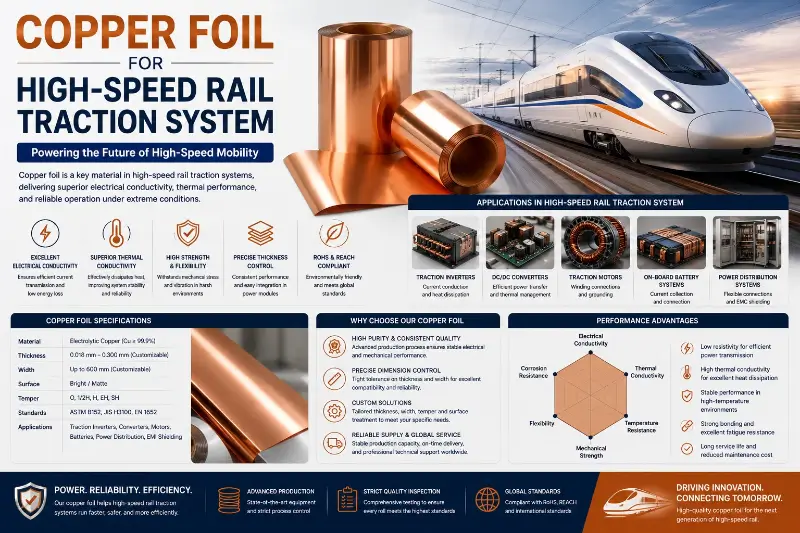
Copper foil for high-speed rail (HSR) traction systems is a high-performance copper-based conductive material specifically designed for key electrical equipment of high-speed EMUs, metros, and electric locomotives such as traction motors, traction transformers, converters, pantographs, and brake resistors. Unlike general-purpose electrical copper foil, HSR traction copper foil must remain stable and reliable in harsh vibration-shock, temperature cycling, electrical loading, and chemical corrosion environments, while meeting stringent railway-industry special requirements on fire protection, low smoke, halogen-free, and service life.
The HSR traction system is the “heart” and “blood vessels” of high-speed trains. It converts the 25 kV / 50 Hz single-phase AC from the catenary into the three-phase AC (or DC) required by the traction motor to drive the train at high speed. The entire traction system involves multiple electrical subsystems including the pantograph, traction transformer, traction converter, traction motor, brake resistor, and auxiliary systems, with copper foil serving as the fundamental conductive material throughout.
From a physics perspective, HSR traction copper foil faces four major engineering challenges. First, extreme vibration and shock: IEC 61373 requires railway equipment to withstand 30 g shock acceleration and 10⁸ vibration cycles without failure, so the copper foil must have excellent mechanical fatigue resistance. Second, temperature cycling: from -40°C (Northern winter) to +180°C (motor operating temperature), the differential thermal expansion between the copper foil and the insulation layer causes interfacial cracking. Third, short-circuit electromagnetic force: the traction transformer must withstand 50 kA short-circuit current impact, and the copper foil winding must resist tremendous axial and radial electromagnetic forces. Fourth, fire protection and flame retardancy: EN 45545-2 HL3 is the highest fire protection level for European rolling stock, requiring low smoke, low toxicity, and halogen-free.
This guide systematically discusses the fundamental concepts, key physical parameters, mainstream product types, typical application scenarios, selection methods, and quality control of copper foil for HSR traction systems from five dimensions, aiming to provide a complete engineering reference for traction motor engineers, traction transformer designers, pantograph supplier technical decision-makers, railway procurement engineers, and OEM R&D engineers.
Fundamental Concepts and Classification of HSR Traction Copper Foil
Definition and Performance Requirements
HSR traction copper foil refers to rectangular or strip-shaped copper conductive material used for key electrical equipment of high-speed trains such as traction motors, traction transformers, converters, pantographs, and brake resistors. Its cross-section is rectangular (thickness 0.10–3.0 mm, width 5–100 mm), supplied as continuous coils in the longitudinal direction. This type of copper foil is the key foundation material for electrical performance, mechanical strength, and reliability of railway equipment.
Compared with general industrial copper foil, HSR traction copper foil has the following seven special requirements:
- Vibration fatigue resistance: IEC 61373 standard, 10⁸ vibration cycles without failure
- Short-circuit electromagnetic force resistance: traction transformer must withstand 50 kA short-circuit current
- Low smoke and halogen-free: fire smoke density < 50 (Ds max), toxicity index < 0.75 (CIT)
- Fire protection and flame retardancy: EN 45545-2 HL3 (highest level)
- Temperature class: Class H 180°C, Class C 220°C
- Service life requirement: 25 years service life, annual operating kilometers 300,000–500,000 km
- Shock resistance: 30 g shock acceleration (transient)
Composition of HSR Traction System
The HSR traction system is the powertrain of high-speed trains, consisting of:
- Pantograph system: pantograph contact strip, catenary wire, ground return device
- Traction transformer: onboard traction main transformer, single-phase oil-immersed
- Traction converter: four-quadrant rectifier, intermediate DC link, inverter (IGBT/SiC)
- Traction motor: asynchronous traction motor (IM) or permanent magnet synchronous motor (PMSM)
- Brake system: regenerative braking, resistor braking, mechanical braking
- Auxiliary system: auxiliary converter, charger, filter, lighting
Copper foil serves as a key conductive function throughout the above systems.
Core Differences from General Industrial Copper Foil
| Dimension | HSR Traction Copper Foil | General Industrial Copper Foil | Construction/Power Copper Foil |
|---|---|---|---|
| Operating temperature | -40°C to +180°C | -20°C to +105°C | -20°C to +90°C |
| Vibration environment | 30 g shock, 10⁸ cycles | Mostly static | Mostly static |
| Short-circuit current | 50 kA | 10 kA | 6 kA |
| Fire protection level | EN 45545-2 HL3 | Ordinary | Ordinary |
| Service life requirement | 25 years | 10–15 years | 30 years |
| Cost | 3–10× | 1× | 1–2× |
| Certification | IRIS + EN 45545 + TB/T | CCC, UL | CCC, CE |
Application Classification
By HSR subsystem type, traction copper foil can be classified into:
- Traction motor stator copper foil: 1.0–3.0 mm thick, 5–25 mm wide, for CRH EMU PMSM
- Traction transformer winding copper foil: 0.10–0.50 mm thick, 20–100 mm wide, for onboard main transformer
- Pantograph contact strip copper base: 2–10 mm thick, 30–60 mm wide, pure copper or copper-graphite
- Brake resistor copper foil: 0.5–2.0 mm thick, 10–80 mm wide, NiCr or FeCrAl
- Converter busbar copper foil: 1.0–5.0 mm thick, 20–200 mm wide, for IGBT/SiC modules
- Ground return copper foil: 0.5–2.0 mm thick, 10–50 mm wide, for carbody grounding
- Auxiliary inductor copper foil: 0.10–0.50 mm thick, 5–30 mm wide, for EMI filters
Key Physical Parameters of HSR Traction Copper Foil
Conductor Materials and Purity
The conductor material of HSR traction copper foil directly affects current-carrying capacity and long-term reliability. Mainstream conductor materials:
Pure Copper (C11000, C10100, C10200)
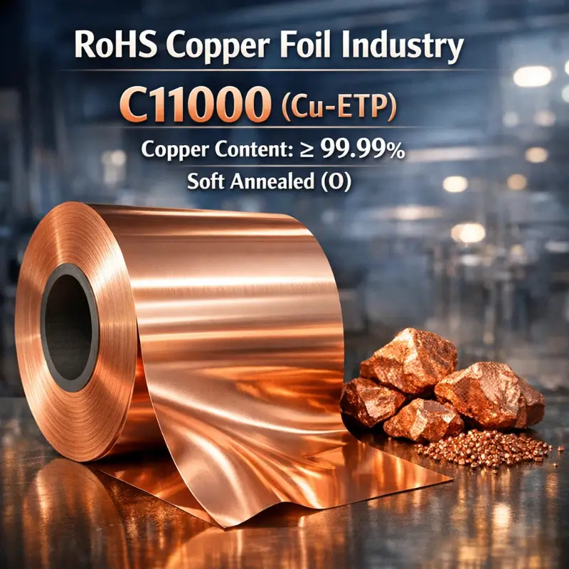
- C11000: purity ≥ 99.95%, conductivity ≥ 100% IACS
- C10100: oxygen-free copper, purity ≥ 99.99%, conductivity ≥ 101% IACS
- C10200: contains deoxidizer, purity ≥ 99.95%
- Application: standard CRH EMU traction motors, traction transformers
High-Purity Copper (6N)
- Purity ≥ 99.9999%
- Conductivity ≥ 102% IACS
- Application: Fuxing high-speed train (CR450)
- Price: 10–50× standard copper
Silver-Copper (AgCu 0.03–0.1%)
- Silver content 0.03%–0.1%
- Improved high-temperature softening resistance
- Softening temperature increased from 200°C to 350°C
- Application: high-temperature traction motors (IE4/IE5)
Chromium-Copper (CuCr 0.5–1.0%)
- Chromium content 0.5%–1.0%
- Tensile strength increased to 450 MPa
- Softening temperature increased to 500°C
- Application: high-temperature traction motors (IE5+)
Nickel-Copper (B10, B30)
- Nickel content 10%–30%
- Seawater corrosion resistance
- Application: coastal / sea-crossing high-speed rail lines
Thickness, Width and Geometric Precision
The geometric precision of HSR traction copper foil directly affects electrical and mechanical performance:
| Application | Thickness | Width | Length |
|---|---|---|---|
| Traction motor stator | 1.0–3.0 mm | 5–25 mm | 50–500 m/coil |
| Traction transformer winding | 0.10–0.50 mm | 20–100 mm | 100–1000 m/coil |
| Pantograph contact strip | 2.0–10 mm | 30–60 mm | 0.5–2 m/section |
| Brake resistor | 0.5–2.0 mm | 10–80 mm | 50–200 m/coil |
| Converter busbar | 1.0–5.0 mm | 20–200 mm | 5–50 m/section |
| Ground return | 0.5–2.0 mm | 10–50 mm | 50–500 m/coil |
Tolerance Requirements:
- Thickness tolerance: ±5% (standard), ±3% (high precision)
- Width tolerance: ±0.2 mm
- Edge burr: ≤ 0.05 mm
- Flatness: ≤ 1 mm/m
Mechanical Strength and Elongation
The mechanical performance parameters of HSR traction copper foil directly affect vibration and short-circuit resistance:
Tensile Strength (Rm)
- Soft (O): 220–280 MPa
- Half-hard (1/2H): 280–350 MPa
- Hard (H): 350–450 MPa
- Extra-hard (EH): 450–550 MPa
Yield Strength (Rp0.2)
- Soft: ≥ 80 MPa
- Half-hard: ≥ 250 MPa
- Hard: ≥ 320 MPa
Elongation (A50)
- Soft: ≥ 35%
- Half-hard: ≥ 15%
- Hard: ≥ 5%
Hardness (HV)
- Soft: 40–60 HV
- Half-hard: 80–110 HV
- Hard: 110–140 HV
Electrical Performance
Conductivity (% IACS)
- C11000 soft: ≥ 100% IACS
- C10100 oxygen-free copper: ≥ 101% IACS
- 6N copper: ≥ 102% IACS
- Tin-plated copper: ≥ 90% IACS
- Temperature coefficient: 0.00393 /°C
Resistance Temperature Characteristics
- 20°C reference resistivity: 1.7241 × 10⁻⁸ Ω·m
- 100°C resistivity: 2.30 × 10⁻⁸ Ω·m
- 200°C resistivity: 2.93 × 10⁻⁸ Ω·m
Skin Depth
- DC–50 Hz: skin depth 9.33 mm (copper), no impact on thickness selection
- 1 kHz: 2.09 mm
- 10 kHz: 0.66 mm (needs consideration at converter switching frequency 1–10 kHz)
Insulation Coating and Enamel Film
The insulation requirements for HSR traction copper foil are among the most stringent in the industry:
Class H (180°C) Enamel Film
- Polyesterimide (EIW): tan δ < 0.012
- Thickness: 30–60 μm
- Breakdown voltage: ≥ 5 kV
- Application: standard CRH EMU
Class C (220°C) Enamel Film
- Polyamide-imide (AIW): tan δ < 0.008
- Thickness: 40–80 μm
- Breakdown voltage: ≥ 7 kV
- Application: Fuxing high-speed train
Special Coatings
- Mica tape: fire protection EN 45545-2 HL3
- Glass fiber wrapping: mechanical protection
- DuPont Nomex paper: high temperature resistance
- Ceramic-filled coating: extreme temperature
Mainstream HSR Traction Copper Foil Product Types
Soft Copper Foil (O Temper)
Soft annealed copper foil (O Temper Copper Foil) undergoes complete annealing treatment, with the highest conductivity, most flexible mechanical performance, and easy forming.
Main Application Scenarios:
- Traction transformer low-voltage windings
- Traction motor stator end
- Busbar flexible connections
- Ground return copper foil
Technical Features:
- Tensile strength: 220–280 MPa
- Elongation: ≥ 35%
- Conductivity: ≥ 100% IACS
- Surface: bright annealed (BA) or passivated
Hard Copper Foil (H Temper)
Hard un-annealed copper foil (H Temper Copper Foil) achieves high strength through cold work hardening, with excellent mechanical performance.
Main Application Scenarios:
- Traction motor stator linear section
- High-strength busbar
- Pantograph contact strip copper base
- High-strength structural components
Technical Features:
- Tensile strength: 350–450 MPa
- Elongation: ≥ 5%
- Conductivity: ≥ 98% IACS
- Surface: bright or tin-plated
Tin-Plated Copper Foil
Tin-plated copper foil (Tin-Plated Copper Foil) has a tin layer (3–10 μm) electroplated on the copper foil surface, providing excellent solderability and oxidation resistance.
Main Application Scenarios:
- Traction motor stator end connections
- Transformer lead wires
- Ground terminals
- Battery/capacitor connection pieces
Technical Features:
- Tin layer thickness: 3–10 μm
- Tin content: ≥ 99.5%
- Solderability: 300°C / 3 s wetting rate > 95%
- Oxidation resistance: 96 h salt spray test without discoloration
- Conductivity: ≥ 90% IACS
Silver-Plated Copper Foil
Silver-plated copper foil (Silver-Plated Copper Foil) has a silver layer (2–8 μm) electroplated on the copper foil surface, providing optimal conductivity and high-frequency performance.
Main Application Scenarios:
- High-frequency converter busbars (SiC modules)
- High-end traction transformer lead wires
- EMI filter copper foil
- Aerospace/aviation derived applications
Technical Features:
- Silver layer thickness: 2–8 μm
- Silver content: ≥ 99.9%
- Conductivity: ≥ 105% IACS
- High-frequency performance: full silver layer within skin depth at 10 kHz
Nickel-Copper Alloy Foil
Nickel-copper alloy foil (Nickel-Copper Alloy Foil) contains 10%–30% nickel with corrosion resistance.
Main Application Scenarios:
- Coastal high-speed rail traction motors
- Marine track / sea-crossing bridge
- High humidity area applications
Technical Features:
- Nickel content: 10%–30%
- Conductivity: 60%–85% IACS
- Corrosion resistance: 1000 h salt spray test
- Tensile strength: 350–500 MPa
Composite Copper Foil (Copper/Aluminum/Stainless Steel Composite)
Composite copper foil (Copper/Aluminum/Stainless Steel Composite Foil) is made of copper layer combined with aluminum or stainless steel layer through metallurgical bonding, combining the advantages of multiple materials.
Main Application Scenarios:
- Lightweight traction motor (copper/aluminum composite)
- High-strength busbar (copper/stainless steel composite)
- High heat-resistance components (copper/titanium composite)
Technical Features:
- Thickness: 0.5–5.0 mm
- Copper layer proportion: 20%–80%
- Weight reduction: 30%–50% (copper/aluminum composite)
- Strength increase: 2–3× (copper/stainless steel composite)
Self-Bonding Copper Foil
Self-bonding copper foil (Self-Bonding Copper Foil) has a thermal-melt bonding layer added outside the insulation layer, which can be heated and cured after winding for solid forming.
Main Application Scenarios:
- Traction motor stator bobbin-less winding
- Transformer coil curing
- End forming
Technical Features:
- Bonding layer: polyamide hot-melt adhesive
- Activation temperature: 180–200°C
- Bond strength: ≥ 10 N/cm
- Operating temperature: Class H 180°C
Traction Motor Stator Winding Applications
Traction Motor Structure and Copper Foil Role
The traction motor is the “heart” of the high-speed train, undertaking the core function of converting electrical energy into mechanical energy. Mainstream types of HSR traction motors:
- Asynchronous traction motor (IM): CRH1, CRH2, CRH3 and other mainstream models
- Permanent magnet synchronous motor (PMSM): CR450 Fuxing, metro Type A car
- Power class: 300 kW–1200 kW (EMU), 200–600 kW (metro)
Core applications of copper foil in traction motors:
- Stator winding: rectangular copper foil winding stator coil
- Rotor bar: asynchronous motor cage bar (copper alloy)
- End connection: copper foil flexible strip connecting stator end
- Temperature sensor: PT100 platinum resistance lead wire
Traction Motor Stator Copper Foil Requirements
Mechanical Requirements
- Vibration resistance: IEC 61373 standard, 10⁸ cycles
- Shock resistance: 30 g shock acceleration
- Centrifugal force resistance: centrifugal force at motor speed 4000–6000 rpm
- Thermal expansion resistance: temperature cycling -40°C to +180°C
Electrical Requirements
- Current density: 5–15 A/mm² (continuous operation)
- Peak current: 20–30 A/mm² (starting acceleration)
- Efficiency: ≥ 96% (IE3 level)
- Power factor: ≥ 0.85
Insulation Requirements
- Enamel class: Class H 180°C (standard) or Class C 220°C (high-end)
- Insulation thickness: 30–80 μm (inter-turn)
- Breakdown voltage: ≥ 5 kV (inter-turn)
- Dielectric loss: tan δ < 0.012
Traction Motor Copper Foil Selection Parameters
| Motor Type | Power | Copper Foil Thickness | Copper Foil Width | Conductor | Enamel |
|---|---|---|---|---|---|
| CRH2 Asynchronous | 300 kW | 1.5–2.0 mm | 8–15 mm | C11000 H | EIW Class H |
| CRH3 Asynchronous | 500 kW | 1.8–2.5 mm | 10–18 mm | C11000 H | EIW Class H |
| CRH5 Asynchronous | 550 kW | 2.0–2.5 mm | 12–20 mm | C11000 1/2H | AIW Class C |
| Fuxing PMSM | 600 kW | 1.5–2.2 mm | 10–16 mm | 6N Cu H | AIW Class C |
| Metro PMSM | 200 kW | 1.0–1.5 mm | 6–12 mm | C11000 H | EIW Class H |
| Maglev LIM | 100 kW | 1.5–3.0 mm | 8–20 mm | C11000 H | PI 220°C |
Traction Motor Copper Foil Design Experience
Slot Fill Optimization
- Target slot fill: >75%
- Copper foil width selection: based on slot shape dimensions
- Insulation thickness: inter-turn 30–50 μm, ground 200–500 μm
Winding End Design
- End height: 30–80 mm
- End binding: glass fiber tape + impregnating varnish
- End forming: hot-press forming or cold-press forming
Cooling System Design
- Water cooling: traction motor housing water jacket
- Forced air cooling: metro traction motor
- Heat dissipation fins: increase heat dissipation area
Traction Transformer and Reactor Applications
Traction Transformer Structure
The traction transformer (Trackside or Onboard Traction Transformer) is the core electrical equipment of the HSR traction system, converting the 25 kV single-phase AC from the catenary into the voltage class required by the traction converter.
Main Types:
- Onboard traction transformer: CRH series EMU, single-phase oil-immersed
- AT supply transformer: autotransformer (AT) power supply mode
- Station traction transformer: ground traction substation
Capacity range: single unit 5–10 MVA.
Traction Transformer Copper Foil Winding
Winding Structure
- High-voltage winding: 25 kV side, multi-layer cylindrical type
- Low-voltage winding: 900 V / 1800 V side, multi-layer cylindrical or pie type
- Voltage regulating winding: on-load voltage regulating tap
Copper Foil Specification
- Thickness: 0.10–0.50 mm (thin foil)
- Width: 20–100 mm (depending on capacity)
- Conductor: C11000, C10100
- Insulation: Class H EIW, Class C AIW, PI
- Interlayer insulation: DuPont Nomex 410 paper
- End insulation: laminated cardboard
Key Performance Requirements
- Dielectric loss: tan δ < 0.008
- Partial discharge: < 5 pC
- Short-circuit withstand: 25 kA / 3 s (asymmetric short circuit)
- Short-circuit electromagnetic force resistance: 50 kA peak
Traction Reactors
Smoothing Reactor
- DC link smoothing
- Inductance: 5–50 mH
- Copper foil: 0.30–0.80 mm thick
- Frequency: 100 Hz (ripple frequency)
Resonance Reactor
- Resonant circuit (LC)
- Inductance: 1–20 mH
- Copper foil: 0.20–0.50 mm thick
EMI Filter Reactor
- Common mode / differential mode filtering
- Operating frequency: 1–10 MHz
- Copper foil: 0.10–0.30 mm thick + Litz wire
Traction Transformer Insulation System
Class H (180°C) Insulation System
- Enamel: EIW (polyesterimide)
- Interlayer: Nomex 410 paper
- Impregnation: Class H impregnating varnish (polyester or epoxy)
- Application: standard CRH EMU
Class C (220°C) Insulation System
- Enamel: AIW (polyamide-imide) + PI
- Interlayer: Nomex 410 + mica tape
- Impregnation: polyimide impregnating varnish
- Application: Fuxing CR450
Special Insulation System
- Fire-protection type: mica tape + glass fiber wrapping (EN 45545-2 HL3)
- Explosion-proof type: gas insulation (SF₆ / dry air)
- Oil-immersed type: mineral oil or ester oil
Pantograph Contact Strip and Current Collection System Applications
Pantograph System Composition
The pantograph is the key equipment for HSR to collect current from the catenary, consisting of:
- Base frame: support structure (aluminum alloy or stainless steel)
- Insulator: high-voltage to ground insulation
- Upper and lower arms: lifting mechanism
- Contact strip: direct contact with contact wire for current collection
- Bow head: contact strip mounting seat
- Contact wire: CuMg / CuSn alloy, cross-section 120–150 mm²
Pantograph Contact Strip Copper Foil
The pantograph contact strip is one of the most critical components for HSR current collection, with its material directly affecting current collection quality and service life.
Pure Copper Contact Strip
- Thickness: 5–10 mm
- Width: 30–60 mm
- Length: 600–1250 mm
- Service life: 30,000–80,000 km
- Application: early CRH models, low-speed metro
Copper-Graphite Composite Contact Strip
- Copper content: 60%–80% (matrix)
- Graphite content: 20%–40% (lubrication)
- Metal impregnation (copper/silver): improve conductivity
- Thickness: 5–25 mm
- Service life: 80,000–150,000 km
- Application: mainstream CRH EMU
Metal-Impregnated Carbon Contact Strip
- Carbon matrix: coke / graphite powder
- Impregnation: copper / silver / antimony
- Thickness: 5–30 mm
- Service life: 150,000–300,000 km
- Application: Fuxing high-speed train, maglev
Special Material Contact Strip
- Titanium alloy contact strip: lightweight, high strength
- Stainless steel contact strip: low cost, wear-resistant
- Composite contact strip: carbon fiber reinforced
Pantograph Contact Strip Key Technical Indicators
| Indicator | Pure Copper | Copper-Graphite | Metal-Impregnated Carbon |
|---|---|---|---|
| Conductivity (% IACS) | ≥ 95% | ≥ 60% | ≥ 30% |
| Hardness (HRB) | 40–60 | 30–50 | 60–90 |
| Flexural strength (MPa) | ≥ 250 | ≥ 150 | ≥ 80 |
| Contact resistance (mΩ) | < 5 | < 10 | < 15 |
| Service life (km) | 30k–80k | 80k–150k | 150k–300k |
| Unit price (yuan/piece) | 500–1500 | 1500–3000 | 3000–8000 |
Catenary and Return System
Contact Wire
- Material: CuMg 0.5% (copper-magnesium alloy), CuSn 0.4% (copper-tin alloy)
- Cross-section: 120 mm², 150 mm²
- Tensile strength: ≥ 550 MPa
- Conductivity: ≥ 70% IACS
- Application: HSR, electrified railway
Messenger Wire
- Material: copper-clad steel, copper-magnesium alloy
- Cross-section: 95 mm², 120 mm²
- Tensile strength: ≥ 650 MPa
- Application: suspended catenary
Ground Return System
- Rail return: 50 kg/m, 60 kg/m rail
- Grounding copper foil: cross-section 50–150 mm²
- Equipotential connection: braided copper strip
- Lightning protection grounding: copper-clad steel grounding electrode
Brake Resistor and Converter Busbar Applications
Brake Resistor Copper Foil
The HSR brake resistor is the core component of the resistor brake system, converting the train’s kinetic energy into heat for dissipation.
Resistance Alloy
- Nickel-chromium alloy (NiCr 80/20): operating temperature 1100°C
- Iron-chromium-aluminum alloy (FeCrAl): operating temperature 1400°C
- Stainless steel (304, 316): operating temperature 900°C
- Pure copper (short-time operation): temperature below 200°C
Copper Foil Specification
- Thickness: 0.5–2.0 mm
- Width: 10–80 mm
- Alloy: Ni80Cr20, 0Cr25Al5
- Insulation: glass fiber wrapping, ceramic coating
- Resistance: 0.5–10 Ω
- Power: 100–800 kW
Key Performance Requirements
- Operating temperature: -40°C to +600°C (short-term +800°C)
- Vibration resistance: IEC 61373
- Fire protection and flame retardancy: EN 45545-2 HL3
- Service life: 25 years
Converter Busbar Copper Foil
The traction converter converts the catenary AC into DC, then inverts it into the three-phase AC required by the traction motor.
Main Circuit Structure
- Four-quadrant rectifier (4QC): IGBT / SiC module
- Intermediate DC link: support capacitor
- Inverter: IGBT / SiC module
- Brake chopper: IGBT module
Busbar Copper Foil Specification
- Thickness: 1.0–5.0 mm
- Width: 20–200 mm
- Conductor: C11000 tin-plated
- Surface treatment: tin-plated, nickel-plated, silver-plated
- Insulation: epoxy resin, heat-shrinkable tube
Key Performance Requirements
- Current-carrying capacity: 1000–3000 A (transient 5000 A)
- Operating voltage: 1800 V DC, 3300 V DC
- Switching frequency: 1–10 kHz
- Skin depth: considered (thickness ≤ 3 mm)
- Stray inductance: < 50 nH
- Heat dissipation: air cooling / water cooling
Auxiliary System Copper Foil Applications
Auxiliary Converter Busbar
- Capacity: 100–300 kVA
- Voltage: DC 110 V, three-phase AC 380 V
- Copper foil: 1.0–3.0 mm thick
Filter Copper Foil
- EMI filter: 0.10–0.50 mm Litz wire
- Common mode inductor: toroidal core + copper foil
- Harmonic suppression: X/Y capacitor + copper foil inductor
Charger Copper Foil
- DC 110 V charger
- Rectifier bridge copper foil
- Filter inductor copper foil
- Thickness: 0.5–2.0 mm
Lighting and Control Copper Foil
- Busbar
- Control signal cable
- Grounding copper strip
Selection Methods and Quality Control for HSR Traction Copper Foil
Selection Decision Matrix
The selection of HSR traction copper foil requires comprehensive consideration of the following factors:
| Selection Factor | Key Question | Impact |
|---|---|---|
| Application scenario | Motor / transformer / pantograph / brake | Determines thickness, width |
| Performance requirements | Current-carrying, short-circuit resistance, efficiency | Determines conductor material |
| Operating temperature | Class H 180°C / Class C 220°C | Determines enamel type |
| Vibration environment | IEC 61373 Class B/C | Determines mechanical strength |
| Fire protection requirements | EN 45545-2 HL3 | Determines insulation system |
| Cost budget | Standard / high-end / flagship | Determines material grade |
| Service life requirement | 25 years, 500,000 km | Determines reliability grade |
| Certification requirements | IRIS, TB/T, UIC | Determines supplier |
Working Temperature and Insulation System Matching
Match enamel film by working temperature and insulation requirements:
| Working Temperature | Recommended Enamel | Interlayer Insulation | Impregnating Varnish | Application |
|---|---|---|---|---|
| ≤ 130°C | PEW (polyester) | Kraft paper | Class A | Low-speed metro |
| 130–155°C | EIW (polyesterimide) | Nomex 410 | Class F | Early CRH |
| 155–180°C | EIW (polyesterimide) | Nomex 410 | Class H | Standard CRH |
| 180–200°C | AIW (polyamide-imide) | Nomex 410 + mica | Class H | High-speed CRH |
| 200–220°C | AIW + PI | Nomex + mica | Class C | Fuxing CR450 |
| 220–240°C | PI (polyimide) | Mica tape | Class C | Maglev |
Vibration and Shock Classes
Per IEC 61373 standard, railway vehicle equipment vibration classes are divided into:
Class A: equipment inside passenger compartment (shock-absorbing mounting)
- Acceleration: 0.1–0.5 g RMS
- Frequency: 1–500 Hz
Class B: equipment outside carbody (cabinet, under-car)
- Acceleration: 0.5–1.0 g RMS
- Frequency: 1–500 Hz
Class C: equipment on bogie (most severe)
- Acceleration: 1.0–5.0 g RMS
- Frequency: 1–500 Hz
- Shock: 30 g / 11 ms
Traction motors, converters and other key equipment are mostly installed under-car or on bogie, belonging to Class B/C level.
Fire Protection and Flame Retardancy Levels
Per EN 45545-2 standard, railway vehicle fire protection levels:
HL1 (low hazard): old lines
- Limit: low
- Application: early electric locomotives
HL2 (medium hazard): ordinary passenger-freight mixed operation
- Limit: medium
- Application: ordinary railway passenger cars
HL3 (high hazard): high-speed rail, metro
- Limit: strict
- Oxygen index: ≥ 32%
- Smoke density: Ds max < 50
- Toxicity index: CIT < 0.75
- Application: CRH, Fuxing, metro
Standards System and Certification
International Standards
- IEC 60317: magnet wire series standards
- IEC 60851: magnet wire test methods
- IEC 61373: railway rolling stock equipment shock and vibration test
- IEC 60077: railway rolling stock electrical equipment
- EN 45545-2: railway vehicle fire protection
- EN 50124-1: railway insulation coordination
- EN 50155: railway electronic equipment
- ISO 9001 / IRIS: quality management system
Railway Industry Standards
- TB/T 3034: railway rolling stock magnet wire (China)
- TB/T 1484: railway rolling stock wire and cable (China)
- TB/T 3150: railway rolling stock EMC (China)
- UIC 558: International Union of Railways standard
- AAR S-501: American Association of Railroads electrical equipment standard
- JIS E 4041: Japan railway standard
OEM Certification
- CRRC (China) certification
- Alstom certification
- Siemens certification
- Bombardier certification
- Kawasaki Heavy Industries certification
Quality Inspection and Reliability Verification
Key Quality Indicators
| Indicator | Requirement | Test Method |
|---|---|---|
| Thickness tolerance | ±5% (standard), ±3% (high precision) | Laser thickness gauge |
| Width tolerance | ±0.2 mm | Caliper |
| Conductivity | ≥ 100% IACS (C11000) | Eddy current conductivity meter |
| Tensile strength | 220–550 MPa | Universal testing machine |
| Elongation | ≥ 5% (hard), ≥ 35% (soft) | Universal testing machine |
| Breakdown voltage | ≥ 5 kV (inter-turn) | High voltage tester |
| Dielectric loss | tan δ < 0.012 | LCR meter |
| Enamel adhesion | 5A or 5B | Cross-cut method |
| Fire protection level | EN 45545-2 HL3 | Cone calorimeter |
| Vibration test | IEC 61373 Class B/C | Vibration table |
| Shock test | 30 g / 11 ms | Shock table |
| Salt spray test | ≥ 96 h | Salt spray chamber |
| Service life test | 25 years accelerated | High temperature aging |
Special Reliability Tests
- Short-circuit test: 50 kA / 3 s, winding without deformation
- Temperature cycling: -40°C to +180°C, 1000 cycles
- Vibration fatigue: 10⁸ cycles
- Damp heat test: 40°C / 93% RH, 1000 h
- Flame retardancy test: EN 45545-2 R1/R7 level
Supplier Evaluation Dimensions
Core dimensions for evaluating HSR traction copper foil suppliers:
- Certification system: ISO 9001 + IRIS + EN 9100 three-system certification
- Industry experience: whether served CRRC, Alstom, Siemens and other OEMs
- Production scale: annual capacity ≥ 5000 tons
- Process equipment: precision rolling mill, annealing furnace, continuous tin-plating / silver-plating line
- Testing capability: ICP spectroscopy, laser thickness measurement, vibration table, shock table
- Quality management: first article inspection, in-process inspection, finished product inspection, factory inspection
- Traceability system: material batch, production batch, inspection batch traceable
- Engineering support: selection calculation, insulation design, fault analysis support
Summary: HSR Traction System Copper Foil Selection Engineering Guide
The application selection of copper foil for HSR traction systems first depends on the application scenario. Traction motor stators (1.0–3.0 mm) require vibration fatigue resistance and high-temperature insulation (Class H 180°C / Class C 220°C). Traction transformer windings (0.10–0.50 mm) require short-circuit electromagnetic force resistance and low dielectric loss. Pantograph contact strips (5–30 mm) require wear resistance and good current collection. Brake resistors (0.5–2.0 mm) require high-temperature resistance (600–800°C) and fire protection flame retardancy. Converter busbars (1.0–5.0 mm) require low stray inductance and high heat dissipation capability. In selection, conductor purity should match the grade (standard CRH 99.95%, Fuxing 99.99%–99.9999%, flagship CR450 99.9999%), enamel selection should satisfy working temperature (Class H EIW, Class C AIW/PI), thickness should satisfy current density (5–15 A/mm² continuous, 20–30 A/mm² peak), and insulation system should satisfy fire protection level (EN 45545-2 HL3).
The core difference between HSR traction copper foil and general industrial copper foil lies in the ultimate pursuit of vibration-shock resistance, short-circuit electromagnetic force resistance, fire protection flame retardancy, and service life reliability. General industrial copper foil focuses on cost, conductivity, and processability, while HSR traction copper foil focuses on IEC 61373 vibration resistance, 50 kA short-circuit electromagnetic force, EN 45545-2 HL3 fire protection level, and 25 years service life. This engineering trade-off determines that HSR traction copper foil must be produced by manufacturers with railway industry certification (IRIS + EN 45545 + TB/T). The process barriers lie in high-purity copper smelting (OFC / 6N copper), precision rolling (thickness tolerance ±3%), annealing control (conductivity and mechanical performance balance), enamel coating (30–80 μm uniform enamel film + breakdown voltage ≥ 5 kV), and composite insulation system design (enamel + Nomex + mica + impregnating varnish). This is also the fundamental reason why HSR traction copper foil prices are typically 3–10 times that of general industrial copper foil, with Fuxing CR450 6N copper magnet wire reaching 10–50 times standard copper foil prices.
The core quality indicators of HSR traction copper foil are vibration fatigue resistance, short-circuit electromagnetic force resistance, and fire protection flame retardancy level. Vibration fatigue resistance is determined by IEC 61373 Class B/C level, requiring 10⁸ vibration cycles without failure. Short-circuit electromagnetic force resistance is verified by 50 kA / 3 s short-circuit test. Fire protection flame retardancy is certified by EN 45545-2 HL3 level (oxygen index ≥ 32%, smoke density Ds max < 50, toxicity index CIT < 0.75). The IEC 60317 series standards provide basic specifications for enamel film, IEC 61373 provides test methods for vibration-shock, EN 45545-2 provides classification basis for fire protection flame retardancy, and TB/T series standards provide product specifications for the Chinese railway industry. In specific applications, comprehensive selection must combine the four dimensions of application scenario, performance grade, certification requirements, and cost budget, prioritizing suppliers with ISO 9001 + IRIS + OEM certification (such as CRRC/CR450 supplier certification) three-system certification. Conductor purity test reports, enamel breakdown voltage and loss tangent measured data, vibration-shock test reports (IEC 61373 level), and fire protection flame retardancy test reports (EN 45545-2 HL3) are the four core dimensions for evaluating the technical capability of HSR traction copper foil suppliers.