


In the engineering design of low-voltage switchgear, control cabinets, and distribution cabinets, the design quality of the grounding system directly determines the safety and electromagnetic compatibility of equipment operation. Copper foil, as a thin and wide strip conductor, has become one of the key materials for the grounding system inside electrical cabinets due to its low impedance, easy bending, and large contact area. This article, starting from the functional division of the grounding system, systematically elaborates on the application scope, material and specification selection, installation process, relevant standards and testing methods of copper foil in electrical cabinet grounding, and discusses common design pitfalls.
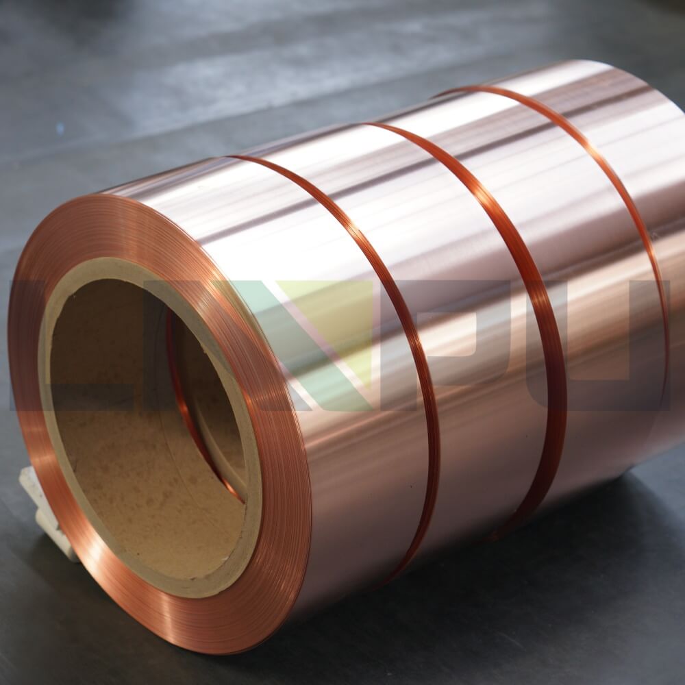
Functional Division of Grounding Systems and the Role of Copper Foil
The grounding system of an electrical cabinet is not a single loop. According to the division of IEC 61439-1 and IEC 60364, the interior of an electrical cabinet typically contains three independent but interconnected paths: protective grounding (PE), functional grounding (FE), and shielding grounding.
The purpose of protective grounding is to conduct fault current to the earth in the event of insulation failure, thereby suppressing the rise of the casing potential. The cross-sectional area of the protective grounding conductor is selected based on the thermal stability requirements of the expected short-circuit current, usually calculated using the I²t method. Copper foil is generally used in protective grounding for equipotential bonding of movable or structural components such as door panels, side panels, and base plates.
Functional grounding provides a stable reference potential for electronic circuits. PLCs, servo drives, and analog acquisition modules are extremely sensitive to the stability of the reference ground; even small fluctuations can lead to sampling errors or logic errors. In such applications, copper foil is typically used as a low-impedance reference ground plane or a local equipotential bonding bus.
Shielding grounding provides a low-inductive return path for high-frequency interference. Common-mode interference generated by equipment such as inverters, rectifiers, and switching power supplies is conducted along the cable shielding towards the cabinet. If the grounding impedance is too high, the interference will create a potential difference between the shielding layer and the ground, causing excessive radiated and conducted emissions. The wide surface structure of copper foil gives it lower inductive reactance than round conductors at high frequencies; therefore, copper foil is often used as an extended grounding electrode at the termination of the shielding layer.
Primary Application Scenarios of Copper Foil
The primary application of copper foil is inside electrical cabinets. Its applications can be broadly categorized as follows.
Door panel grounding is one of the most common applications. Door panels are connected to the cabinet via hinges, which may experience poor contact due to oxidation or mechanical wear over time. Most standards require the door panel to be connected to the main grounding busbar of the cabinet via an independent grounding conductor. Copper foil, typically 0.1 mm to 0.3 mm thick, can be concealed under door seams or rubber strips, making it the most commonly used material for this application. The width of the copper foil for door panel grounding is generally 20 mm to 50 mm, and the length is determined by the door panel dimensions. Both ends are connected to the hinges, door panel reinforcing ribs, and the main grounding busbar of the cabinet via copper terminals or direct crimping.
Shielding termination is another crucial application. When shielded control cables and signal cables enter the cabinet, the shielding layer needs to be 360° looped at the entry point or connected to the cabinet via a low-impedance path. Copper foil is often used as an extension conductor between the shielding termination clip and the cabinet to increase the contact area and reduce contact resistance.
Surge protector (SPD) grounding requires conductors to be short, straight, and thick. Copper foil is widely used in the connection section between the SPD grounding terminal and the main grounding busbar. Compared to round conductors of the same cross-sectional area, it has lower parasitic inductance and stronger transient current discharge capability.
Busbar extensions and T-connections frequently occur during assembly. When the main grounding busbar is insufficient in length or a branch needs to be led out from the side, cutting a section of copper foil and crimping it to copper terminals is a simple and low-cost solution.
Cabinet parallel grounding is used for multiple sets of equipment installed side-by-side. Each cabinet needs to be interconnected via equipotential bonding strips to establish a common reference ground. Copper foil can be used to connect the grounding screws of multiple cabinets in series at once, resulting in high installation efficiency.
Materials and Alloy Systems
The choice of copper foil material directly determines its conductivity, mechanical properties, and corrosion resistance. Industrial copper foil mainly uses the following types of copper and copper alloys.
C11000 (electrolytic copper, ETP) is the most commonly used material for grounding copper foil. It has a copper content of no less than 99.9%, an electrical conductivity of approximately 100% IACS, a density of 8.89 g/cm³, a tensile strength of 220–300 MPa, and an elongation of 15%–45%. C11000 has excellent conductivity and good processing performance, making it the preferred material for protective and functional grounding.
C12200 (deoxidized copper, DHP) is used in applications requiring high-temperature brazing or reducing atmospheres. It has a copper content of no less than 99.9% and an electrical conductivity of approximately 85% IACS. Compared to C11000, C12200 is less prone to hydrogen embrittlement during welding.
C19400 (copper-iron alloy) is used in applications requiring higher mechanical strength. It has an electrical conductivity of approximately 60% IACS and a tensile strength exceeding 500 MPa. This material retains its shape after stamping and bending, making it suitable for grounding structural components requiring complex forming and high strength.
The surface treatment of copper foil has a significant impact on long-term reliability. Bare copper in the atmosphere forms cuprous oxide and copper oxide, and in humid environments, it further forms basic copper carbonate, commonly known as verdigris. The resistivity of the oxide layer is much higher than that of pure copper, causing contact resistance to increase several times to tens of times within a few months.
Tin plating is the most common surface treatment for grounding copper foil in electrical cabinets. The tin layer thickness is typically 3 μm to 8 μm, providing several years of oxidation protection at room temperature and atmospheric conditions. Tin is less hard than copper, allowing for good intermetallic contact with the copper substrate during crimping. The tin plating layer also slowly oxidizes in the atmosphere to form tin dioxide, but its resistivity is much lower than that of copper oxidation products, resulting in a smaller impact on contact resistance.
Nickel plating is typically 2 μm to 5 μm thick, with higher hardness and abrasion resistance than tin, making it suitable for applications requiring frequent disassembly or mechanical friction. Nickel’s resistivity is approximately four times that of copper; its impact on overall impedance must be evaluated when used in high-current or high-frequency applications.
Engineering Selection of Thickness and Width
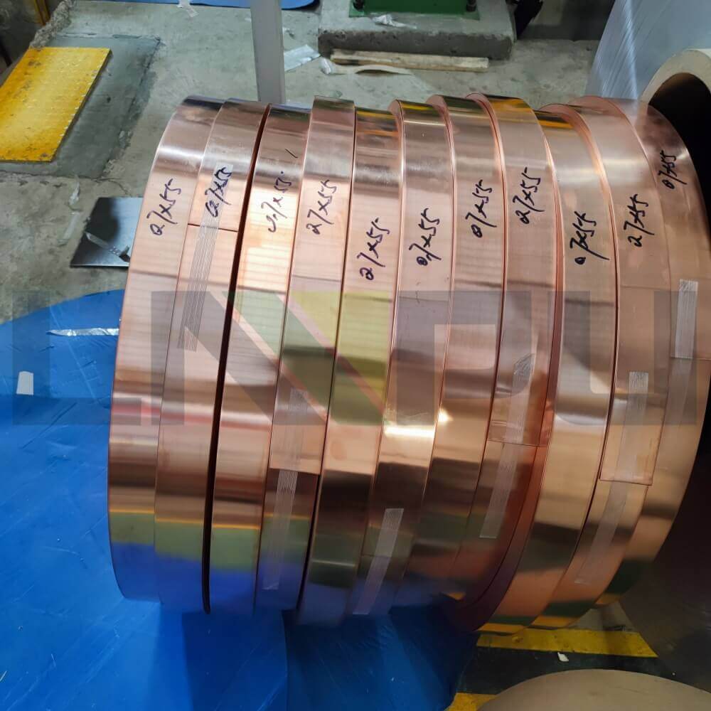
The selection of copper foil thickness needs to consider conductivity, mechanical strength, and installation processability. The commonly used thickness range for grounding copper foil is 0.05 mm to 0.5 mm.
Copper foil with a thickness of 0.05 mm to 0.1 mm is mainly used for signal-level shielding and light-load grounding. Its tensile strength is relatively low, and its current-carrying capacity is limited, making it unsuitable for direct screw crimping; it requires welding or conductive adhesive bonding for fixation. Copper foil in this thickness range is commonly used in shielded rooms and local shielding of sensitive electronic equipment.
Copper foil with a thickness of 0.2 mm is the most commonly used for electrical cabinet door grounding, shield grounding, and SPD grounding. Its mechanical strength is sufficient to withstand the crimping of M5 to M6 screws, and it can be punched and bent, offering good processability. Under natural cooling and a 30 K temperature rise, 0.2 mm thick, 50 mm wide C11000 copper foil can carry approximately 100 A of continuous current, while a 100 mm wide foil of the same thickness can carry approximately 200 A. Its short-time carrying capacity (1 s fault current) is approximately 20–30 times that of continuous current carrying capacity.
Copper foil with a thickness of 0.3 mm to 0.5 mm is used for high-current grounding, vibration environments, or applications requiring higher mechanical strength, such as near the neutral point of a transformer, generator outlets, and power distribution cabinet grounding. Copper foil in this thickness range requires specialized tools for bending, but its tensile and shear strength are significantly improved.
Width selection is primarily based on current carrying capacity, contact area, and mechanical stability. Practical experience in computer room anti-static grounding projects shows that 30 mm, 40 mm, 50 mm, and 100 mm are the four most commonly used widths, each corresponding to different application scenarios: 30 mm is suitable for signal level and light load protective grounding; 50 mm is a general choice for door grounding and shield grounding; and 100 mm is suitable for high-current SPD grounding and extensions of main grounding bars.
The minimum cross-sectional area of the protective grounding conductor must meet the thermal stability requirements of the expected short-circuit current. Based on a copper conductor with a temperature rise of 30 K and a short-circuit time of 5 s, the minimum cross-sectional area is 6 mm² for expected short-circuit currents below 1.5 kA, 10 mm² for 1.5–3 kA, 16 mm² for 3–5 kA, 25 mm² for 5–10 kA, and 35–50 mm² for 10–25 kA. Taking 0.2 mm thick copper foil as a reference, a 6 mm² cross-section corresponds to a width of 30 mm, 10 mm² to 50 mm, and 16 mm² to 80 mm. This correspondence is the direct reason why 50 mm wide copper foil is widely used in the industry.
Installation Process and Connection Methods
There are four main installation methods for copper foil: screw crimping, welding, conductive adhesive bonding, and braided tape crimping. Each method is suitable for different application conditions.
Screw crimping is the most common connection method. Before crimping, holes need to be punched at the ends of the copper foil or copper terminals need to be installed. The edges of the holes should be chamfered to eliminate stress concentration. Screws are usually M5 or M6, used with spring washers and flat washers. The function of the flat washer is to increase the crimping area and prevent the screw head from cutting into the copper foil during vibration and causing breakage. This is especially critical in the installation of thin copper foil. The tightening torque of the screws needs to be controlled according to specifications: M5 screws are usually 2.5–3 N·m, and M6 screws are 4–5 N·m. Insufficient torque leads to increased contact resistance, while excessive torque can cause plastic deformation or even tearing of the copper foil.
Welding provides the lowest contact resistance and the highest mechanical strength. For soldering, it is recommended to use silver-containing solder wire (Ag content not less than 2%). Ordinary tin-lead solder may fail under high current conditions due to electromigration. When soldering copper foil to aluminum or galvanized steel cabinets, a dedicated copper-aluminum transition joint or brazing filler metal must be used; direct soldering is not permitted.
Conductive adhesive bonding is suitable for control cabinets where open flames are not permitted or where components are already installed. 3M 1181, 1182, and 1183 series copper foil tapes are typical products for this application, offering shielding effectiveness of 60–80 dB in the 30 MHz to 1 GHz frequency band. It should be noted that the contact resistance of conductive adhesive is 5–10 times higher than screw crimping and is only suitable for signal-level shielded grounding, not for protective grounding.
Braided tape crimping is used for transition connections between copper foil and copper braided tape, typically found in SPD grounding and high-current gate grounding loops. Crimping should be done using hexagonal or square dies, and the crimping height must meet the requirements of UL 467 or IEC 61238.
The choice of installation location is equally important. Copper foil should be kept away from directly above high-power heat-generating components inside the cabinet, with a distance of at least 30 mm, to prevent long-term heat radiation from accelerating the formation of an oxide layer on the copper foil surface. When routing cables along the cabinet walls, sharp edges should be avoided; rubber sleeves or cable trays should be installed if necessary. Sufficient bending allowance should be provided for the copper foil on the door panel to ensure it remains taut during door opening and closing, preventing metal fatigue fracture due to repeated bending.
Relevant Standards and Certification Requirements
The design and selection of grounding copper foil for electrical cabinets must comply with multiple international and domestic standards.
IEC 61439-1 is the basic standard for low-voltage switchgear assemblies, and its clause 10.10 sets forth clear requirements for the cross-sectional area, connection method, and test method of the grounding conductor. The cross-sectional area of the protective conductor must be determined based on the thermal stability requirements of the expected short-circuit current, and its temperature rise under fault conditions must be verified to not exceed the limit.
UL 467 (Grounding and Bonding Equipment) is a mandatory certification standard in the US market for grounding connectors, grounding clamps, and grounding strips. Grounding copper foil assemblies used in complete sets of equipment exported to North America require this certification, and the corresponding terminals and crimping processes must also meet the relevant requirements. The corresponding standard in Canada is CSA C22.2 No. 41.
NEC Article 250 (Grounding and Bonding) specifies detailed requirements for grounding in the US National Electrical Code, covering protective grounding conductor dimensions, equipment grounding conductor selection, and grounding electrode systems.
IEC 62305 is a series of standards for building lightning protection, which clearly specifies the conductor cross-sectional area, materials, and connection methods for grounding devices. When copper foil is used as a lightning arrester down conductor or surge protector grounding conductor, it must meet the requirements of this standard.
GB/T 50065-2011 specifies the grounding design code for AC electrical installations and is a mandatory basis for the design of complete sets of equipment in China. GB 50057-2010 is the design code for lightning protection of buildings, and both are frequently referenced in the design of lightning protection grounding systems.
TIA/EIA 607 is the standard for grounding and connection of communication systems in commercial buildings, mainly applicable to communication cabinets and data center computer rooms. This standard provides detailed specifications for grounding network topology, conductors, and connection methods, and is the main reference for grounding design of network cabinets and server cabinets.
Testing and Acceptance Methods
After the copper foil grounding system is installed, the system should be tested and accepted.
Grounding continuity test: Use a microohmmeter or four-wire method to measure the grounding path resistance. The resistance from the equipment casing to the main grounding busbar is generally required to be no more than 0.1 Ω, and the resistance for paths less than 1 m in length should be no more than 0.05 Ω. During measurement, the influence of other parallel paths should be eliminated, and relevant connections should be disconnected if necessary to obtain an accurate loop resistance.
Insulation resistance test: Use a 500 V megohmmeter to measure the insulation resistance between the copper foil and other live parts of the cabinet; the resistance value should be greater than 1 MΩ.
Mechanical inspection includes checking the screw tightening torque and door opening/closing tests. The tightening torque for M5 screws should be within the range of 2.5–3 N·m, and for M6 screws, within the range of 4–5 N·m. The copper foil for grounding the door panel must undergo at least 50 opening and closing tests to check for deformation and loosening of the crimping points.
Environmental adaptability testing is necessary for critical projects. After a salt spray test according to GB/T 10125 or ASTM B117 for 96 hours, the plating should show no red rust. A temperature rise test with 1.5 times the rated current for 7 hours should result in a contact temperature rise of less than 50 K. A vibration test involving triaxial vibration for 2 hours within the range of 10–500 Hz should result in a contact resistance change of less than 5%.
Complete test records should include the specifications/models of each grounding copper foil, installation location, crimping torque, measured resistance value, test date, and personnel information. These records form the basis for subsequent equipment maintenance and certification audits.
Common Design and Construction Issues
In engineering practice, the design and construction of copper foil grounding often encounter the following types of problems.
Using copper foil for high-current main grounding busbars is a common mistake. The current-carrying capacity and mechanical strength of copper foil are far lower than those of copper busbars. Using it for main grounding busbars may result in excessive temperature rise or mechanical deformation under continuous high current or short-circuit current. Main grounding busbars should use copper busbars with a thickness of at least 3 mm; copper foil should only be used for auxiliary connections and extensions.
Direct lap joints of dissimilar metals are another common problem. Copper and aluminum will undergo electrochemical corrosion in humid environments; copper-aluminum transitions must use dedicated copper-aluminum transition busbars or flash welding joints, and cannot be simply covered with copper foil.
Omitting flat washers during crimping will cause the copper foil to be gradually cut under the screw head and break, especially in applications with thin copper foil (0.1–0.2 mm thick), this problem is extremely common. All screw crimping points must be equipped with flat washers, and the diameter of the washers should be at least twice the diameter of the screw head.
Confusion regarding copper foil thickness direction markings is a common oversight in supply chain and field management. Copper foil rolls are typically labeled with “thickness × width”. If a 0.2 mm thickness is mistakenly ordered as 0.02 mm, the copper foil will be unable to withstand basic mechanical operations. Thickness and tolerances should be clearly defined when ordering and upon delivery.
The issue of material consistency caused by mixing spare parts cannot be ignored in large projects. Copper foil from different manufacturers and batches may differ in purity, hardness, conductivity, and surface treatment. Critical projects should use copper foil from the same manufacturer and batch, and maintain material traceability records.
Selection Decision Points
Based on the above analysis, the selection of copper foil for electrical cabinet grounding can be decided from the following four dimensions.
Current carrying capacity is the primary constraint. Under 30 K temperature rise and natural cooling conditions, 0.2 mm thick, 50 mm wide copper foil can carry approximately 100 A of continuous current, and 0.3 mm thick, 50 mm wide copper foil can carry approximately 150 A. For applications with continuous current exceeding 200 A, a 0.3 mm thicker, wider foil should be selected, or a copper busbar should be used instead.
Environmental conditions determine the surface treatment method. Bare copper or tin plating can be used in dry indoor environments; tin plating with a thickness of not less than 5 μm should be used in outdoor or humid environments; nickel plating or thicker tin plating should be used in corrosive environments such as chemical plants and coastal areas.
Installation space and method determine the thickness selection. 0.2 mm thickness should be selected for applications requiring bending, such as door panels and shielding layer terminations; 0.3 mm thickness should be selected for applications requiring higher mechanical strength, such as SPD grounding and high-current connections; 0.1 mm thickness can be selected for signal-level shielding.
Target market and certification requirements determine the selection of materials and components. Equipment exported to North America should use grounding components certified by UL 467; the European market should comply with IEC 61439-1; the Chinese market should comply with GB/T 50065.
Conclusion
Copper foil is a key material in electrical cabinet grounding systems; its material selection, specification determination, installation process, and testing and acceptance must strictly follow relevant standards and engineering experience. In practical projects, the specifications and surface treatment of copper foil should be comprehensively determined based on current carrying capacity, environmental conditions, installation space, and certification requirements. The long-term reliability of the grounding system should be ensured through standardized installation processes and systematic testing and acceptance. Understanding the functional role of copper foil in the grounding system and avoiding common design and construction pitfalls are fundamental to ensuring the safe operation and electromagnetic compatibility of electrical cabinets.