


Enameled wire (also known as magnet wire or winding wire) specifications face the coexistence of two global standard systems within international supply chains: the North America–dominated AWG (American Wire Gauge) system and the globally prevalent metric mm (millimeter) diameter system. Significant differences exist between these two systems in coding logic, mathematical derivation, physical parameters, diameter tolerances, cross-sectional area, electrical performance, and application conventions—causing frequent confusion among engineers and procurement professionals in motor, transformer, home appliance, automotive electronics, and medical device sectors when selecting, comparing, or converting enameled wire specifications. This article systematically compares AWG and metric mm enameled wire across coding rules, mathematical relationships, diameter tolerances, cross-sectional area, resistance, weight, current-carrying capacity, design selection, and trade practices; provides complete conversion formulas, reference tables, and engineering selection strategies; and aims to support enameled wire engineers, procurement specialists, and trade professionals in efficiently achieving specification interoperability, substitution, and global supply chain management between the AWG and mm systems.
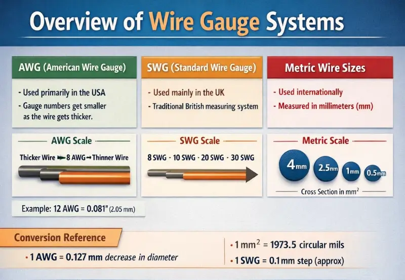
Overview of Wire Gauge Systems
The wire gauge system for magnet wire is the core coding method for identifying wire diameter. The major global gauge systems include AWG (American Wire Gauge), metric mm, B&S, SWG (Standard Wire Gauge), and BWG (Birmingham Wire Gauge). Each system has distinct coding rules, derivation logic, and application scopes.
Primary Wire Gauge Systems
AWG (American Wire Gauge):
AWG is the predominant wire gauge system in North America, developed by Brown & Sharpe in 1857, and is one of the most important specifications systems in the magnet wire industry.
Metric mm (Millimeter) System:
The metric system (mm) is the globally predominant wire gauge system, widely adopted in Europe, China, Japan, South Korea, and other regions.
SWG (Standard Wire Gauge, British Standard Wire Gauge):
SWG is the British traditional wire gauge system, established in 1844 by the English Legal Standard Wire Gauge.
BWG (Birmingham Wire Gauge):
BWG is a traditional wire gauge standard originating from Birmingham, UK, primarily used for steel pipes, copper pipes, and steel plates.
Other wire gauges:
- B&S (Brown & Sharpe): i.e., AWG alias
- MCM / kcmil: Thousand Circular Mils, used for large cross-section cables
- French Gauge / Metric Wire Gauge: French wire gauge
Current Application Status of Magnet Wire Specifications
Application conventions for magnet wire specifications across different regions:
| Region | Primary Specification | Secondary Specification |
|---|---|---|
| USA | AWG | mm |
| Canada | AWG | mm |
| UK | mm | SWG |
| Germany | mm | — |
| France | mm | — |
| Italy | mm | — |
| Spain | mm | — |
| China | mm | AWG (trade) |
| Japan | mm | AWG (trade) |
| Korea | mm | AWG (trade) |
| India | mm | SWG |
| Brazil | mm | AWG |
| Australia | mm | AWG |
Detailed Explanation of AWG Wire Gauge System
AWG is the most important wire gauge system in the magnet wire industry, especially used in North America, Southeast Asia, and parts of Europe.
AWG History and Definition
– Developed in 1857 by Brown & Sharpe Company
– Standardizing organization: ASTM B258 (wire gauge standard)
– Magnet wire industry standards: NEMA MW 1000, IEC 60317
AWG Coding Rule (Core):
Two fixed-diameter reference points:
– AWG 36 = 0.127 mm = 0.005 inch (standard reference)
– AWG 0000 (4/0) = 11.684 mm = 0.4600 inch (maximum size)
– AWG 000 (3/0) = 10.405 mm
– AWG 00 (2/0) = 9.266 mm
– AWG 0 (1/0) = 8.252 mm
– AWG 1 = 7.348 mm
– AWG 50 = 0.025 mm (theoretical limit, not used in practice)
Diameter changes by a fixed ratio per N-grade increment/decrement:
- Per 1 AWG increment: diameter ratio = 92^((36−n)/39)
- Per 1 AWG increment: cross-sectional area ratio = 92^((36−n)/19) (square of diameter)
- Per 1 AWG increment: weight ratio ≈ 2.05×
- Per 1 AWG increment: resistance ratio ≈ 0.488× (approximately 1/2)
AWG mathematical formula:
Diameter Formula (d = diameter):
– dₙ (inch) = 0.005 × 92^((36−n)/39)
– dₙ (mm) = 0.127 × 92^((36−n)/39)
– dₙ (cmil) = 1000 × 92^((36−n)/19)
Cross-sectional area formulas:
– Aₙ (kcmil) = 1000 × 92^((36−n)/19)
– Aₙ (mm²) = (π/4) × dₙ(mm)²
Resistance Formula (annealed copper at 20 °C):
– Rₙ (Ω/1000 ft) ≈ 0.3048 × 10¹² / (58 × dₙ² mil²)
– Or simplified: Rₙ (Ω/km) ≈ 0.01724 / Aₙ (mm²)
Weight Formula (Copper Conductor):
– Wₙ (lbs/1000 ft) ≈ 8.89 × Aₙ (mm²) × 0.305 / 1000
AWG Number Meaning:
- The smaller the AWG number, the larger the diameter.
- AWG 0000 (4/0) is the thickest commonly used gauge.
- AWG 44 is the finest commonly used gauge.
- AWG numbers change incrementally, reflecting the wire drawing process during manufacturing.
AWG Wire Drawing Process Fundamentals:
- Each draw reduces diameter by 1 AWG (approximately 10.9% reduction)
- Cross-sectional area is halved per draw
- Weight is halved per draw
- Length doubles per draw
Metric mm Wire Gauge System
The metric mm system is the most widely adopted wire gauge system globally in the magnet wire industry, particularly in Europe and Asia.
Metric mm Standard History
- ISO—the core international standardization body
- The International System of Units (SI) was formally adopted by the International Committee for Weights and Measures in 1959
- Magnet wire industry standards: IEC 60317, GB/T 6109, JIS C 3202, DIN 46435
Metric mm numbering system:
Standard Diameter Series (IEC 60317, GB/T 6109):
- Preferred metric round wire diameters (mm):
0.020, 0.025, 0.032, 0.040, 0.050, 0.063, 0.071, 0.080, 0.090, 0.100, 0.112, 0.125, 0.140, 0.160, 0.180, 0.200, 0.224, 0.250, 0.280, 0.315, 0.355, 0.400, 0.450, 0.500, 0.560, 0.630, 0.710, 0.800, 0.900, 1.000, 1.120, 1.250, 1.400, 1.600, 1.800, 2.000, 2.240, 2.500, 2.800, 3.150, 3.550, 4.000, 4.500, 5.000, 5.600, 6.000 mm
R Series (Renard Series, Preferred Numbers):
- R20 preferred numbers: 1.0, 1.12, 1.25, 1.40, 1.60, 1.80, 2.0, 2.24, 2.50, 2.80, 3.15, 3.55, 4.0, 4.50, 5.00, 5.60, 6.30, 7.10
- R40 preferred numbers: finer gradation (10% increments)
Metric Diameter Characteristics:
- Direct reading of actual diameter (mm)
- Digital continuous scale
- Simple correspondence with physical quantities (area, volume)
- Global mainstream standards (IEC, ISO, GB, DIN, JIS)
Metric mm diameter tolerance:
Enameled Wire Metric Diameter Tolerance Standard (IEC 60317):
| Diameter Range | Standard Tolerance | Precision Tolerance |
|---|---|---|
| ≤0.100 mm | ±0.003 mm | ±0.002 mm |
| 0.100–0.250 mm | ±0.005 mm | ±0.003 mm |
| 0.250–0.500 mm | ±0.008 mm | ±0.005 mm |
| 0.500–0.900 mm | ±0.010 mm | ±0.008 mm |
| 0.900–1.500 mm | ±0.013 mm | ±0.010 mm |
| 1.500–2.500 mm | ±0.025 mm | ±0.013 mm |
| 2.500–4.000 mm | ±0.040 mm | ±0.025 mm |
| 4.000–6.000 mm | ±0.060 mm | ±0.040 mm |
Mathematical Conversion Between AWG and Metric mm
Conversion between AWG and metric mm is a core competency required of magnet wire engineers.
AWG to mm Conversion Formula
Exact formula (applicable to any AWG):
d (mm) = 0.127 × 92^((36−n)/39)
Simplified Formula (applicable to AWG 0–44):
d (mm) ≈ 0.127 × (1.122932)^(36−n)
Common AWG-to-mm Conversion Table:
| AWG | Diameter (mm) | Diameter (inch) | Ratio to Previous Gauge |
|---|---|---|---|
| 0000 (4/0) | 11.684 | 0.4600 | Reference |
| 000 (3/0) | 10.404 | 0.4096 | ×0.891 |
| 00 (2/0) | 9.266 | 0.3648 | ×0.891 |
| 0 (1/0) | 8.252 | 0.3249 | ×0.891 |
| 1 | 7.348 | 0.2893 | ×0.890 |
| 2 | 6.544 | 0.2576 | ×0.891 |
| 3 | 5.827 | 0.2294 | ×0.890 |
| 4 | 5.189 | 0.2043 | ×0.890 |
| 5 | 4.621 | 0.1819 | ×0.890 |
| 6 | 4.115 | 0.1620 | ×0.890 |
| 7 | 3.665 | 0.1443 | ×0.891 |
| 8 | 3.264 | 0.1285 | ×0.890 |
| 9 | 2.906 | 0.1144 | ×0.890 |
| 10 | 2.588 | 0.1019 | ×0.891 |
| 11 | 2.305 | 0.0907 | ×0.891 |
| 12 | 2.053 | 0.0808 | ×0.891 |
| 13 | 1.828 | 0.0720 | ×0.890 |
| 14 | 1.628 | 0.0641 | ×0.891 |
| 15 | 1.450 | 0.0571 | ×0.890 |
| 16 | 1.291 | 0.0508 | ×0.890 |
| 17 | 1.150 | 0.0453 | ×0.891 |
| 18 | 1.024 | 0.0403 | ×0.890 |
| 19 | 0.912 | 0.0359 | ×0.891 |
| 20 | 0.813 | 0.0320 | ×0.891 |
| 21 | 0.724 | 0.0285 | ×0.890 |
| 22 | 0.643 | 0.0253 | ×0.884 |
| 23 | 0.574 | 0.0226 | ×0.893 |
| 24 | 0.511 | 0.0201 | ×0.890 |
| 25 | 0.455 | 0.0179 | ×0.890 |
| 26 | 0.404 | 0.0159 | ×0.888 |
| 27 | 0.361 | 0.0142 | ×0.893 |
| 28 | 0.320 | 0.0126 | ×0.886 |
| 29 | 0.287 | 0.0113 | ×0.897 |
| 30 | 0.255 | 0.0100 | ×0.888 |
| 31 | 0.227 | 0.00893 | ×0.890 |
| 32 | 0.202 | 0.00795 | ×0.890 |
| 33 | 0.180 | 0.00708 | ×0.891 |
| 34 | 0.160 | 0.00630 | ×0.889 |
| 35 | 0.143 | 0.00562 | ×0.894 |
| 36 | 0.127 | 0.00500 | ×0.888 |
| 37 | 0.114 | 0.00449 | ×0.898 |
| 38 | 0.101 | 0.00397 | ×0.886 |
| 39 | 0.090 | 0.00353 | ×0.891 |
| 40 | 0.080 | 0.00314 | ×0.889 |
Metric mm to AWG Conversion Formula
Exact Formula:
n (AWG) = 36 − 39 × log₁₀(d_mm / 0.127) / log₁₀(92)
n (AWG) = 36 − 39 × log₁₀(d_mm × 7.87402) / log₁₀(92)
Simplified formula:
n (AWG) ≈ -39 × log₁₀(d_mm / 0.127) / log₁₀(92) + 36
Reverse calculation (from mm to AWG):
- d = 0.100 mm: AWG ≈ 38
- d = 0.160 mm: AWG ≈ 34
- d = 0.255 mm: AWG ≈ 30
- d = 0.404 mm: AWG ≈ 26
- d = 0.511 mm: AWG ≈ 24
- d = 0.643 mm: AWG ≈ 22
- d = 0.813 mm: AWG ≈ 20
- d = 1.024 mm: AWG ≈ 18
- d = 1.291 mm: AWG ≈ 16
- d = 1.628 mm: AWG ≈ 14
- d = 2.053 mm: AWG ≈ 12
- d = 2.588 mm: AWG ≈ 10
Conversion Accuracy Considerations
- AWG is a discrete gauge system (each 0.001 mm does not correspond to an AWG number).
- The AWG number provides only an “approximate” target diameter.
- The actual enameled wire diameter shall be calculated according to the AWG standard tolerances.
- Millimeters (mm) constitute a continuous scale and can be specified to any required precision.
Example:
- Standard AWG 22 diameter: 0.643 mm (theoretical value)
- Actual enameled wire diameter: 0.642–0.652 mm (within tolerance)
- Corresponding metric diameter: 0.643 ± 0.013 mm (metric tolerance)
Complete AWG vs mm Conversion Table (Practical)
The table below provides the most commonly used AWG-to-mm conversions in the magnet wire industry, covering AWG 8–44, with diameters ranging from 0.080 mm to 3.264 mm.
| AWG | Diameter (mm) | Diameter (inch) | Cross-sectional Area (mm²) | Resistance (Ω/km at 20°C, copper) | Weight (kg/km, copper) |
|---|---|---|---|---|---|
| 4/0 | 11.684 | 0.4600 | 107.22 | 0.1608 | 953.6 |
| 3/0 | 10.404 | 0.4096 | 85.03 | 0.2027 | 756.4 |
| 2/0 | 9.266 | 0.3648 | 67.43 | 0.2557 | 599.7 |
| 1/0 | 8.252 | 0.3249 | 53.48 | 0.3224 | 475.7 |
| 1 | 7.348 | 0.2893 | 42.41 | 0.4066 | 377.0 |
| 2 | 6.544 | 0.2576 | 33.62 | 0.5126 | 299.0 |
| 3 | 5.827 | 0.2294 | 26.67 | 0.6465 | 237.2 |
| 4 | 5.189 | 0.2043 | 21.15 | 0.8152 | 188.1 |
| 5 | 4.621 | 0.1819 | 16.77 | 1.028 | 149.1 |
| 6 | 4.115 | 0.1620 | 13.30 | 1.296 | 118.3 |
| 7 | 3.665 | 0.1443 | 10.55 | 1.634 | 93.8 |
| 8 | 3.264 | 0.1285 | 8.366 | 2.061 | 74.4 |
| 9 | 2.906 | 0.1144 | 6.632 | 2.599 | 59.0 |
| 10 | 2.588 | 0.1019 | 5.261 | 3.277 | 46.8 |
| 11 | 2.305 | 0.0907 | 4.172 | 4.131 | 37.1 |
| 12 | 2.053 | 0.0808 | 3.309 | 5.211 | 29.5 |
| 13 | 1.828 | 0.0720 | 2.624 | 6.571 | 23.4 |
| 14 | 1.628 | 0.0641 | 2.081 | 8.281 | 18.5 |
| 15 | 1.450 | 0.0571 | 1.652 | 10.44 | 14.7 |
| 16 | 1.291 | 0.0508 | 1.309 | 13.17 | 11.6 |
| 17 | 1.150 | 0.0453 | 1.039 | 16.61 | 9.24 |
| 18 | 1.024 | 0.0403 | 0.823 | 20.95 | 7.32 |
| 19 | 0.912 | 0.0359 | 0.653 | 26.42 | 5.81 |
| 20 | 0.813 | 0.0320 | 0.519 | 33.31 | 4.61 |
| 21 | 0.724 | 0.0285 | 0.411 | 41.95 | 3.66 |
| 22 | 0.643 | 0.0253 | 0.324 | 52.95 | 2.88 |
| 23 | 0.574 | 0.0226 | 0.259 | 66.79 | 2.30 |
| 24 | 0.511 | 0.0201 | 0.205 | 84.22 | 1.82 |
| 25 | 0.455 | 0.0179 | 0.163 | 106.1 | 1.45 |
| 26 | 0.404 | 0.0159 | 0.128 | 133.9 | 1.14 |
| 27 | 0.361 | 0.0142 | 0.1023 | 168.5 | 0.91 |
| 28 | 0.320 | 0.0126 | 0.0804 | 212.9 | 0.715 |
| 29 | 0.287 | 0.0113 | 0.0647 | 265.6 | 0.575 |
| 30 | 0.255 | 0.0100 | 0.0509 | 338.6 | 0.453 |
| 31 | 0.227 | 0.00893 | 0.0404 | 426.7 | 0.360 |
| 32 | 0.202 | 0.00795 | 0.0320 | 538.3 | 0.286 |
| 33 | 0.180 | 0.00708 | 0.0254 | 677.9 | 0.226 |
| 34 | 0.160 | 0.00630 | 0.0201 | 854.4 | 0.180 |
| 35 | 0.143 | 0.00562 | 0.0160 | 1075 | 0.143 |
| 36 | 0.127 | 0.00500 | 0.0126 | 1361 | 0.112 |
| 37 | 0.114 | 0.00449 | 0.0102 | 1680 | 0.090 |
| 38 | 0.101 | 0.00397 | 0.0080 | 2164 | 0.071 |
| 39 | 0.090 | 0.00353 | 0.00636 | 2719 | 0.057 |
| 40 | 0.080 | 0.00314 | 0.0050 | 3441 | 0.044 |
| 41 | 0.071 | 0.00280 | 0.00396 | 4343 | 0.035 |
| 42 | 0.063 | 0.00249 | 0.00314 | 5494 | 0.028 |
| 43 | 0.056 | 0.00222 | 0.00249 | 6921 | 0.022 |
| 44 | 0.050 | 0.00197 | 0.00197 | 8756 | 0.018 |
Diameter Tolerance Differences
There are differences in the diameter tolerance specifications between the AWG and mm systems.
AWG Tolerance Specification (refer to ASTM B258, NEMA MW 1000):
- AWG tolerance vs. diameter:
- AWG 36–44: ±0.001 inch (±0.025 mm)
- AWG 24–35: ±0.001 inch (±0.025 mm) → per certain standards: ±0.0005 inch
- AWG 14–23: ±0.002 inch (±0.050 mm)
- AWG 4–13: ±0.005 inch (±0.125 mm)
- AWG 0000–3: ±0.005–0.010 inch
- AWG Enamel Wire Standard Tolerances:
- Diameter ≤ 1.0 mm: ±0.013 mm
- Diameter 1.0–2.0 mm: ±0.020 mm
- Diameter > 2.0 mm: ±0.030 mm
Metric mm Tolerance Specification (Reference IEC 60317):
- Diameter ≤ 0.100 mm: ±0.003 mm
- 0.100–0.250 mm: ±0.005 mm
- 0.250–0.500 mm: ±0.008 mm
- 0.500–0.900 mm: ±0.010 mm
- 0.900–1.500 mm: ±0.013 mm
- 1.500–2.500 mm: ±0.025 mm
- 2.500–4.000 mm: ±0.040 mm
- 4.000–6.000 mm: ±0.060 mm
Tolerance Comparative Analysis:
| Diameter | AWG Actual Tolerance (mm) | mm Tolerance (mm) | Difference Description |
|---|---|---|---|
| 0.10 mm | ±0.025 | ±0.003 | AWG much looser |
| 0.50 mm | ±0.025 | ±0.008 | AWG looser |
| 1.00 mm | ±0.025 | ±0.013 | AWG looser |
| 1.50 mm | ±0.050 | ±0.025 | AWG looser |
| 2.00 mm | ±0.050 | ±0.025 | AWG looser |
| 3.00 mm | ±0.050–0.125 | ±0.040 | mm tighter |
| 5.00 mm | ±0.125 | ±0.060 | mm tighter |
Design Recommendations:
- Consider original tolerances when converting between AWG and mm.
- Metric mm tolerances are preferred for stringent application requirements.
- For high-precision winding applications, verify the supplier’s actual tolerance capability.
- For cross-section–sensitive applications, prioritize standards with tighter tolerances.
Cross-Sectional Area Conversion
Cross-sectional area is the core parameter in magnet wire design, determining current-carrying capacity and resistance.
Cross-sectional area calculation formula:
AWG cross-sectional area:
Aₙ (mm²) = π/4 × dₙ(mm)²
Aₙ (mm²) = π/4 × (0.127 × 92^((36−n)/39))²
Metric mm² cross-sectional area:
A (mm²) = π/4 × d (mm)²
Circular mil (cmil):
- 1 cmil = (0.001 inch)² = π/4 × (0.001 inch)² = 5.067 × 10⁻¹⁰ m²
- A (cmil) = 1000 × d² (inch)²
- 1 cmil = π/4 × (0.0254)² / 1 mm² ≈ 5.067 × 10⁻⁴ mm²
- 1 mm² ≈ 1973.5 cmil
Common Cross-Sectional Area Conversion Table:
| AWG | mm² Cross-sectional Area (mm²) | cmil | cmil/1000 (kcmil) |
|---|---|---|---|
| 8 | 8.366 | 16,510 | 16.51 |
| 10 | 5.261 | 10,380 | 10.38 |
| 12 | 3.309 | 6,530 | 6.53 |
| 14 | 2.081 | 4,107 | 4.11 |
| 16 | 1.309 | 2,583 | 2.58 |
| 18 | 0.823 | 1,624 | 1.62 |
| 20 | 0.519 | 1,022 | 1.02 |
| 22 | 0.324 | 640.4 | 0.64 |
| 24 | 0.205 | 404.0 | 0.40 |
| 26 | 0.128 | 252.8 | 0.25 |
| 28 | 0.0804 | 158.2 | 0.16 |
| 30 | 0.0509 | 100.0 | 0.10 |
mm diameter directly corresponds to cross-sectional area:
| Diameter (mm) | Cross-sectional Area (mm²) | Diameter (mm) | Cross-sectional Area (mm²) |
|---|---|---|---|
| 0.10 | 0.00785 | 1.20 | 1.131 |
| 0.20 | 0.0314 | 1.50 | 1.767 |
| 0.30 | 0.0707 | 1.80 | 2.545 |
| 0.40 | 0.1257 | 2.00 | 3.142 |
| 0.50 | 0.1963 | 2.50 | 4.909 |
| 0.60 | 0.2827 | 3.00 | 7.069 |
| 0.70 | 0.3848 | 3.50 | 9.621 |
| 0.80 | 0.5027 | 4.00 | 12.566 |
| 0.90 | 0.6362 | 5.00 | 19.635 |
| 1.00 | 0.7854 | 6.00 | 28.274 |
Current-carrying capacity comparison:
- Doubling the cross-sectional area → approximately doubling the current-carrying capacity
- The actual current-carrying capacity must consider:
- Permissible temperature rise
- Ambient temperature
- Installation method
- Insulation class
Resistance Conversion
Electrical resistance is a core electrical property of magnet wire and is closely related to wire diameter.
Basic resistance formula (annealed copper at 20°C):
- R (Ω/km) = 0.01724 / A (mm²)
- ρ₂₀°C = 0.01724 Ω·mm²/m = 1.724 × 10⁻⁸ Ω·m
Resistance vs. AWG:
- Rₙ (Ω/1000 ft) ≈ 0.3048 × 10¹² / (58 × d²ₘᵢₗ)
- Or simplified: Rₙ (Ω/km) ≈ 17.2 / Aₙ (mm²)
Temperature coefficient of resistance:
- Copper (20 °C): 0.00393 /°C
- R(T) = R(20 °C) × [1 + 0.00393 × (T − 20 °C)]
Resistance calculation at common temperature points:
- R(60°C) = R(20°C) × 1.157
- R(75°C) = R(20°C) × 1.216
- R(105°C) = R(20°C) × 1.334
- R(155°C) = R(20°C) × 1.530
- R(180°C) = R(20°C) × 1.630
Resistance vs. diameter (mm):
| Diameter (mm) | Cross-sectional Area (mm²) | Resistance (Ω/km at 20°C) | Voltage Drop per Meter Length (1 A) |
|---|---|---|---|
| 0.10 | 0.00785 | 2196 | 2196 mV |
| 0.20 | 0.0314 | 549 | 549 mV |
| 0.30 | 0.0707 | 244 | 244 mV |
| 0.40 | 0.1257 | 137 | 137 mV |
| 0.50 | 0.1963 | 87.8 | 87.8 mV |
| 0.60 | 0.2827 | 60.9 | 60.9 mV |
| 0.80 | 0.5027 | 34.3 | 34.3 mV |
| 1.00 | 0.7854 | 21.9 | 21.9 mV |
| 1.20 | 1.131 | 15.2 | 15.2 mV |
| 1.50 | 1.767 | 9.76 | 9.76 mV |
| 2.00 | 3.142 | 5.49 | 5.49 mV |
| 2.50 | 4.909 | 3.51 | 3.51 mV |
| 3.00 | 7.069 | 2.44 | 2.44 mV |
AWG Corresponding Resistance (Inverse to Cross-Sectional Area):
| AWG | Diameter (mm) | Resistance (Ω/km at 20°C) |
|---|---|---|
| 8 | 3.264 | 2.06 |
| 10 | 2.588 | 3.28 |
| 14 | 1.628 | 8.28 |
| 18 | 1.024 | 20.95 |
| 22 | 0.643 | 52.95 |
| 26 | 0.404 | 133.86 |
| 30 | 0.255 | 338.58 |
| 36 | 0.127 | 1361 |
| 40 | 0.080 | 3441 |
Design Recommendations:
- Selection between AWG and mm requires consideration of electrical design accuracy.
- DC resistance is closely related to conductivity.
- Skin effect (skin depth) must be considered at high frequencies.
- Loss calculations require extrapolation of the 20 °C standard resistance to other temperatures.
Weight Conversion
The weight of magnet wire directly affects material cost, equipment selection, and transportation planning.
Copper Weight Calculation Formula:
AWG Weight Calculation:
Wₙ (lb/1000 ft) ≈ 0.00305 × dₙ² (mil)
Wₙ (kg/km) ≈ Wₙ (lb/1000 ft) × 0.3048 × 1.609
mm Weight Calculation:
W (kg/km) = d(mm)² × (π/4) × 8.89 / 1000
W (kg/km) = d(mm)² × 0.00698
Common AWG weights:
| AWG | Diameter (mm) | Length (m/kg) | Weight (kg/km) |
|---|---|---|---|
| 8 | 3.264 | 13.4 | 74.4 |
| 10 | 2.588 | 21.4 | 46.8 |
| 12 | 2.053 | 33.9 | 29.5 |
| 14 | 1.628 | 54.1 | 18.5 |
| 16 | 1.291 | 86.2 | 11.6 |
| 18 | 1.024 | 137.0 | 7.32 |
| 20 | 0.813 | 217.0 | 4.61 |
| 22 | 0.643 | 347.0 | 2.88 |
| 24 | 0.511 | 549.0 | 1.82 |
| 26 | 0.404 | 877.0 | 1.14 |
| 28 | 0.320 | 1399 | 0.715 |
| 30 | 0.255 | 2208 | 0.453 |
| 32 | 0.202 | 3497 | 0.286 |
| 34 | 0.160 | 5556 | 0.180 |
| 36 | 0.127 | 8929 | 0.112 |
| 38 | 0.101 | 14085 | 0.071 |
| 40 | 0.080 | 22727 | 0.044 |
Common copper weight per unit length (g/m) vs. wire diameter (mm):
| Diameter (mm) | Weight (kg/km) | Length (m/kg) |
|---|---|---|
| 0.10 | 0.0698 | 14320 |
| 0.20 | 0.279 | 3582 |
| 0.30 | 0.628 | 1592 |
| 0.40 | 1.117 | 895.7 |
| 0.50 | 1.745 | 573.1 |
| 0.60 | 2.513 | 397.9 |
| 0.70 | 3.421 | 292.3 |
| 0.80 | 4.467 | 223.9 |
| 0.90 | 5.654 | 176.8 |
| 1.00 | 6.981 | 143.2 |
| 1.20 | 10.05 | 99.5 |
| 1.50 | 15.71 | 63.7 |
| 2.00 | 27.92 | 35.8 |
| 2.50 | 43.63 | 22.9 |
| 3.00 | 62.83 | 15.9 |
Engineering significance of weight conversion:
- Magnet wire procurement is quoted by weight (kg/t).
- Magnet wire usage is calculated by length (m/km).
- Accurate specifications are required for precise conversion between length and weight.
- Material utilization is considered during magnet wire design.
Current Carrying Capacity Comparison
Current-carrying capacity is a critical engineering parameter for magnet wire selection.
Fundamental Concept of Current-Carrying Capacity:
- Current-carrying capacity: the continuous current permitted to flow through enameled wire under specified conditions
- Influencing factors:
- Conductor diameter (cross-sectional area)
- Permissible temperature rise
- Ambient temperature
- Heat dissipation conditions
- Insulation class
- Enamel coating thickness
Relationship between current-carrying capacity and cross-sectional area:
- Doubling the cross-sectional area increases current-carrying capacity by approximately 50–60% (not 100%).
- Recommended current density: 3–10 A/mm² (magnet wire).
- High-frequency motors: 3–5 A/mm².
- Power-frequency motors: 5–7 A/mm².
AWG Magnet Wire Typical Current-Carrying Capacity (50/60 Hz, Class B Insulation):
| AWG | Diameter (mm) | Cross-sectional Area (mm²) | Current-Carrying Capacity (A) | Recommended Current Density (A/mm²) |
|---|---|---|---|---|
| 8 | 3.264 | 8.366 | 70–90 | 9–11 |
| 10 | 2.588 | 5.261 | 50–65 | 9–12 |
| 12 | 2.053 | 3.309 | 35–45 | 10–13 |
| 14 | 1.628 | 2.081 | 25–32 | 12–15 |
| 16 | 1.291 | 1.309 | 18–22 | 13–16 |
| 18 | 1.024 | 0.823 | 12–15 | 14–18 |
| 20 | 0.813 | 0.519 | 8–10 | 15–19 |
| 22 | 0.643 | 0.324 | 5–7 | 15–21 |
| 24 | 0.511 | 0.205 | 3.5–4.5 | 17–22 |
| 26 | 0.404 | 0.128 | 2.5–3.0 | 19–23 |
| 28 | 0.320 | 0.0804 | 1.5–2.0 | 18–24 |
| 30 | 0.255 | 0.0509 | 1.0–1.3 | 19–25 |
mm — Magnet Wire Current-Carrying Capacity (Reference):
| Diameter (mm) | Cross-sectional Area (mm²) | Current-Carrying Capacity (A) |
|---|---|---|
| 0.30 | 0.0707 | 1.2–1.5 |
| 0.50 | 0.1963 | 3–4 |
| 0.80 | 0.5027 | 7–10 |
| 1.00 | 0.7854 | 11–14 |
| 1.20 | 1.131 | 16–20 |
| 1.50 | 1.767 | 25–32 |
| 2.00 | 3.142 | 45–55 |
| 2.50 | 4.909 | 70–85 |
| 3.00 | 7.069 | 100–120 |
Ampacity Comparison Method:
Comparison at Same Diameter:
- Diameter 1.0 mm ≈ AWG 18 (actual AWG 18 = 1.024 mm)
- Diameter 0.5 mm ≈ AWG 24 (actual AWG 24 = 0.511 mm)
- Diameter 2.0 mm ≈ AWG 12 (actual AWG 12 = 2.053 mm)
Comparison at Same Cross-Sectional Area:
- 1.0 mm² ≈ AWG 17 (actual 1.039 mm²)
- 0.5 mm² ≈ AWG 20 + close
- 2.0 mm² ≈ AWG 14 – close
Recommended current-carrying capacity:
- Standard magnet wire application: 3–5 A/mm²
- High slot-fill applications: 2–3 A/mm²
- High-reliability applications (with large safety margin): 5–7 A/mm²
- Long-term high-temperature operation: 3–4 A/mm²
- Short-term peak-load operation: up to 10 A/mm²
Comparison of National Standards and Numbering Conventions
Standards for magnet wire vary across countries in terms of specification designation, test methods, and nomenclature.
U.S. NEMA MW 1000
- Specification designation: AWG (diameter) + Grade (enamel coating grade) + Thermal Class
- Standard nomenclature: MW 35-C AWG 24 Grade 2 Class 130
- Diameter tolerance: ±0.001 inch (diameter < 1 mm)
EU IEC 60317
- Specification designation: mm (diameter) + Grade + Thermal Class
- Standard nomenclature: IEC 60317-2 0.500 mm Grade 2 Class 130
- Diameter tolerance: according to mm system
China GB/T 6109, GB/T 7095
- Specification designation: mm (diameter) + Grade + Insulation Class
- Standard nomenclature: GB/T 6109.2 0.500 mm Grade 2 Class 130
- Diameter tolerance: per mm system
Japan JIS C 3202
- Specification designation: mm (diameter) + coating type + thickness
- Standard nomenclature: UEW 0.5 1 (diameter 0.5 mm, medium coating, corresponding to IEC Grade 2)
- Diameter tolerance: according to the mm system
UK BS 6811
- Specification designation: mm (diameter) + Grade + Class
- Equivalent adoption of IEC 60317
National numbering system comparison:
| Item | USA | Europe | China | Japan |
|---|---|---|---|---|
| Primary specification | AWG | mm | mm | mm |
| Diameter designation | AWG # | 0.500 mm | 0.500 mm | 0.5 |
| Enamel coating grade designation | Grade 1/2/3 | Grade 1/2/3 | 1/2/3 | 0/1/2 |
| Thermal class designation | Class 130 | Class F (155°C) | Class 130 | 130°C |
| Standard number | NEMA MW 1000 | IEC 60317 | GB/T 6109 | JIS C 3202 |
Magnet Wire Design Recommendations:
- Export products: metric mm (more global)
- North American sales: AWG
- Internationally accepted: dual marking in mm + equivalent AWG
AWG vs mm Design Selection Strategy
Magnet wire selection and design require comprehensive consideration of multiple factors, including specification systems, electrical performance, cost, and supply chain.
Selection Decision Tree
Decision 1: Application Region
- North American market: AWG primarily used
- European/Asian/global markets: mm primarily used
- Global market: mm (better compatibility)
Decision 2: Application Field
- General-purpose household appliances: either mm or AWG acceptable
- Precision motors: strict mm tolerances
- High-power transformers: large mm cross-sections
- High-frequency motors: precise mm specifications
- Aerospace: stringent mm tolerances
Decision 3: Procurement Factors
- Inventory convenience: Extensive AWG stock available
- Supply chain: mm offers better international compatibility
- Cost: Minimal difference between the two
- Trade: mm is globally accepted
Decision 4: Compatibility Requirements
- Replacement of existing products: using original specifications
- International product: mm
- North American certification: AWG
- CE marking: mm is more compliant
AWG-to-mm Gauge Equivalence Selection
Equivalent Diameter Pairing (Design Reference):
| AWG | mm Diameter | Application Matching Description |
|---|---|---|
| 14 | 1.6 mm | Transformer main winding |
| 16 | 1.3 mm | Standard motor |
| 18 | 1.0 mm | Standard motor |
| 20 | 0.8 mm | Small motor |
| 22 | 0.65 mm | Micro motor |
| 24 | 0.50 mm | Small transformer |
| 26 | 0.40 mm | Relay |
| 28 | 0.32 mm | Small relay |
| 30 | 0.25 mm | Electronic coil |
| 32 | 0.20 mm | Micro motor |
| 34 | 0.16 mm | High-frequency winding |
| 36 | 0.13 mm | Micro inductor |
| 38 | 0.10 mm | Micro coil |
| 40 | 0.08 mm | Ultra-fine application |
Selection Strategy Recommendations
Scenarios favoring the mm system:
- New product design
- Global market
- CE/RoHS certification
- Cross-regional production
- Tight tolerance requirements
Scenarios favoring the AWG system:
- Designed for the North American market
- Existing product maintenance
- Ready-to-ship AWG inventory
- North American certification requirements
Equivalent Replacement Strategy:
- Use the same mm value (refer to the conversion table) when replacing the original AWG specification.
- Use the same cross-sectional area when replacing AWG with mm.
- Prioritize precise diameter for high-frequency applications.
- Prioritize precise cross-sectional area for high-power applications.
Common Misconceptions and Pitfalls Between AWG and mm
Misconception 1: AWG number has a linear relationship with wire diameter
- Error: A decrease of 1 in AWG number = a decrease of 1 mm in diameter
- Correct: A decrease of 6 in AWG number ≈ doubling of diameter; a decrease of 1 in AWG number ≈ a 10.9% increase in diameter
- Example: AWG 22 = 0.643 mm; AWG 16 = 1.291 mm (difference of 6 AWG steps, diameter approximately doubled)
Misconception 2: Identical Numerical Designations Indicate Identical Wire Diameters
- Error: AWG 14 = 14 mm or approximate
- Correct: AWG 14 = 1.628 mm (unrelated to the numeric value)
- Note: AWG is a historical coding system with no direct correlation to modern dimensional standards
Misconception 3: AWG and mm are fully interchangeable
- Incorrect: AWG 22 is fully equivalent to a wire diameter of 0.643 mm.
- Correct: AWG 22 = 0.643 mm (theoretical value), within the tolerance range for actual magnet wire.
- Note: Actual product specifications must be verified against the supplier’s datasheet.
Misconception 4: Neglecting temperature correction in resistance conversion
- Incorrect: Resistance is calculated at the standard temperature of 20°C only.
- Correct: Motor operating temperature must be considered, as resistance varies with temperature (copper: 0.00393/°C).
- Resistance at 155°C is 53% higher than at 20°C.
Misconception 5: Directly converting AWG to weight
- Error: Unit-length weight of AWG 18 = π/4 × 18²
- Correct: Unit-length weight of AWG 18 (1.024 mm) = π/4 × 1.024² × 8.89 = 7.32 kg/km
- Note: AWG numbers are not used in weight calculations
Misconception 6: Ignoring the Skin Effect
- Misconception: Larger diameter is always better.
- Correct: At high frequencies, a larger diameter increases AC resistance due to the skin effect.
- Use Litz wire for high-frequency applications.
Misconception 7: All metric mm dimensions are standard
- Incorrect: 0.5 mm must be a standard diameter.
- Correct: mm-diameter wire follows the R-series preferred numbers; non-preferred numbers may not be stocked.
- Stocked diameters: 0.050, 0.063, 0.071, 0.080, 0.090, 0.100…
Misconception 8: Wires of the Same Specification from Different Manufacturers Are Interchangeable
- Error: AWG 24 wires from two manufacturers are identical.
- Correct: AWG 24 wires from different manufacturers may differ in enamel coating class and thermal class.
- Application: Verify the complete specification (AWG + enamel coating + thermal class).
Misconception 9: The enamel coating increases the overall diameter but leaves the cross-sectional area unchanged
- Incorrect: The enamel coating thickness does not affect the conductor resistance.
- Correct: The enamel coating does not increase the conductor cross-sectional area; the conductor diameter equals the bare wire diameter.
- Note: The enamel coating results in an overall diameter greater than the conductor diameter.
Misconception 10: Ignoring changes in temperature index
- Error: All AWG 14 magnet wire is of the same temperature class.
- Correct: Identical diameter may correspond to different temperature classes (130°C, 155°C, 180°C, 220°C, 240°C).
- Application: Verify the temperature class specified in the catalog against the intended application.
Other Wire Gauge Systems (SWG, BWG)
In addition to AWG and metric mm, there are several secondary wire gauge systems used globally.
SWG (Standard Wire Gauge, British Standard Wire Gauge)
SWG History and Definition:
- Established in 1844 by the English Legal Standard Wire Gauge
- Primarily used in the United Kingdom, Australia, and India
- The most widely adopted international standard in the 19th century
- Now largely superseded by metric mm dimensions
SWG Key Diameter:
| SWG | Diameter (mm) | Diameter (inch) |
|---|---|---|
| 14 | 2.032 | 0.0800 |
| 16 | 1.626 | 0.0640 |
| 18 | 1.219 | 0.0480 |
| 20 | 0.914 | 0.0360 |
| 22 | 0.711 | 0.0280 |
| 24 | 0.559 | 0.0220 |
| 26 | 0.457 | 0.0180 |
| 28 | 0.376 | 0.0148 |
| 30 | 0.315 | 0.0124 |
| 32 | 0.274 | 0.0108 |
| 34 | 0.234 | 0.0092 |
| 36 | 0.193 | 0.0076 |
| 38 | 0.152 | 0.0060 |
| 40 | 0.122 | 0.0048 |
| 42 | 0.102 | 0.0040 |
| 44 | 0.0816 | 0.0032 |
BWG (Birmingham Wire Gauge)
BWG History and Definition:
– Used in the Birmingham region of England in the 19th century
– Primarily employed for tubing and sheet metal
– Rarely used in the modern magnet wire industry
BWG key diameter:
| BWG | Diameter (mm) | Diameter (inch) |
|---|---|---|
| 14 | 2.108 | 0.0830 |
| 16 | 1.651 | 0.0650 |
| 18 | 1.245 | 0.0490 |
| 20 | 0.889 | 0.0350 |
| 22 | 0.711 | 0.0280 |
| 24 | 0.559 | 0.0220 |
| 26 | 0.457 | 0.0180 |
| 28 | 0.356 | 0.0140 |
| 30 | 0.305 | 0.0120 |
Wire Gauge System Comparison
Key differences among the three specification systems:
- AWG: Dominant in North America
- mm: Global standard
- SWG: Traditional British standard
- BWG: British wire gauge for tubing
Wire Gauge Conversion (Approximate):
- AWG 22 ≈ SWG 21 ≈ 0.64 mm
- AWG 18 ≈ SWG 17 ≈ 1.0 mm
- AWG 14 ≈ SWG 14 ≈ 1.6 mm
Magnet Wire Specification Certification and Standardization
Magnet wire specifications, under the context of globalization and regulatory compliance, must meet multiple standard systems.
Industrial Practice for Magnet Wire Specification Marking:
- USA NEMA MW 1000: AWG dominant
- EU IEC 60317: mm dominant
- China GB/T 6109: mm dominant
- Japan JIS C 3202: mm dominant
- UK BS 6811: mm dominant (equivalent to IEC 60317)
- Canada CSA C22.2 No. 0: AWG dominant (equivalent to USA)
- Germany DIN 46435: mm dominant
- France NF C 31-600: mm dominant
- Korea KS C 3116: mm dominant
- India IS 13730: mm dominant (equivalent to IEC 60317)
Magnet wire certification markings:
- UL (Underwriters Laboratories): for North America
- VDE (Verband der Elektrotechnik, Elektronik und Informationstechnik): for Europe
- CCC (China Compulsory Certification): for China
- KC (Korea Certification): for Korea
- PSE (Product Safety Electrical Appliance & Materials): for Japan
- CE (Conformité Européenne): for the European Union
Coating Specification Designation:
- NEMA (USA): MW + number + -C
- IEC (International): IEC 60317-X
- GB (China): GB/T 6109.X
- JIS (Japan): coating abbreviation + diameter
Practical Application of Magnet Wire Gauge Selection
Magnet wire gauge selection is a common task in engineering design and requires a systematic approach.
Design Requirement Analysis
Step 1: Clarify Application Requirements
- Operating voltage
- Rated current
- Operating temperature
- Operating frequency
- Dimensional constraints
- Lifetime requirements
Step 2: Calculate the cross-sectional area
- A (mm²) = I / J
- J = current density (3–7 A/mm²)
- A determines the lower limit of wire gauge
Step 3: Select the Specification System
– North America/Canada: AWG
– Europe/Asia: mm
– Global: mm (better compatibility)
Step 4: Select the enamel coating grade
- High Slot Fill Ratio: Grade 1
- Standard Application: Grade 2
- High-Voltage Reliability: Grade 3
Step 5: Select Thermal Class
– Actual operating temperature + 15–25 °C safety margin
– Consider impregnating resin temperature class
Step 6: Select the Enamel Type
- High-frequency: UEW
- Standard: PEW
- Heat-resistant: AIW/PI
- Solderable: UEW
Step 7: Verify Standards
- Verify compliance with IEC 60317 / NEMA MW 1000 specifications
- Verify UL/VDE certification
Step 8: Verify the supply chain
- Inventory availability
- Lead time
- Price level
Global Supply Chain Management
Multi-Specification Inventory Strategy:
- Stocked in AWG 8–44 (serving the North American market)
- Stocked in primary metric sizes mm 0.10–3.00 (serving Europe/Asia)
- Dual-specification equivalents (AWG + mm equivalents)
Supplier Management:
– North American suppliers: primarily AWG gauge
– European/Asian suppliers: primarily mm gauge
– Universal suppliers: dual gauge
Trade Practice:
- Export to North America: identified by AWG
- Export to Europe/Asia: identified by mm
- Test report: specify the dimensional system used
Conclusion
AWG and metric mm are the two most important specification systems in the magnet wire industry, with AWG dominant in North America and metric mm prevailing globally. These two specification systems exhibit significant differences in coding logic, mathematical derivation, physical parameters, and application conventions, yet they are interrelated and can be precisely converted.
Core Principles of the Magnet Wire Specification System:
- Understanding the nature of gauge systems: AWG is a historical coding system (based on the logarithmic relationship of the wire drawing process), while mm is a modern metric continuous scale.
- Mastering the mathematical conversion relationship: The precise conversion formula between AWG and mm (d_mm = 0.127 × 92^((36−n)/39)), and familiarity with commonly used reference tables.
- Understanding tolerance differences: AWG tolerances are relatively loose, whereas mm tolerances are stricter; selection of the appropriate system depends on the application.
- Cross-sectional area and current-carrying capacity: Cross-sectional area directly determines current-carrying capacity; performance is identical for the same cross-sectional area, regardless of whether AWG or mm is used.
- Resistance and temperature: Resistance is nominal at 20°C, but the temperature coefficient must be considered under actual operating temperatures (copper: 0.00393/°C).
- Weight and cost: Weight is calculated based on cross-sectional area and is independent of the gauge system; however, procurement is quoted by weight (kg/t).
- Regional selection strategy: AWG in North America, mm globally; mm is preferred for new product design.
- Standards and certifications: Coexistence of multiple standards, including NEMA MW 1000, IEC 60317, GB/T 6109, and JIS C 3202.
- Other gauge systems: SWG (British) and BWG (Birmingham) are secondary systems rarely used in the magnet wire industry.
- Supply chain management: Maintain dual-specification inventory (AWG and mm) to serve global markets.
Magnet wire engineers, designers, procurement personnel, and trading professionals should systematically master the mutual recognition and application of AWG and mm gauge systems through structured learning (AWG mathematical principles, mm standard system, conversion formulas, reference tables), tool-assisted methods (converters, calculators, CAD software), supplier collaboration (bidirectional specifications, technical specification documents), and market insight (regional preferences, certification requirements), thereby ensuring precise magnet wire selection, efficient substitution, and reliable supply in global markets, and providing core support for the global manufacturing of electrical equipment such as motors, transformers, and inductors.